EP2192306A1 - Dachlüfter - Google Patents
Dachlüfter Download PDFInfo
- Publication number
- EP2192306A1 EP2192306A1 EP08170376A EP08170376A EP2192306A1 EP 2192306 A1 EP2192306 A1 EP 2192306A1 EP 08170376 A EP08170376 A EP 08170376A EP 08170376 A EP08170376 A EP 08170376A EP 2192306 A1 EP2192306 A1 EP 2192306A1
- Authority
- EP
- European Patent Office
- Prior art keywords
- housing
- roof
- fan according
- roof fan
- impeller
- Prior art date
- Legal status (The legal status is an assumption and is not a legal conclusion. Google has not performed a legal analysis and makes no representation as to the accuracy of the status listed.)
- Granted
Links
- 238000006243 chemical reaction Methods 0.000 claims abstract description 11
- 239000000725 suspension Substances 0.000 description 4
- 238000010276 construction Methods 0.000 description 2
- 230000015572 biosynthetic process Effects 0.000 description 1
- 238000007664 blowing Methods 0.000 description 1
- 230000001419 dependent effect Effects 0.000 description 1
- 238000004519 manufacturing process Methods 0.000 description 1
- 238000002844 melting Methods 0.000 description 1
- 230000008018 melting Effects 0.000 description 1
- 238000000034 method Methods 0.000 description 1
- 230000004048 modification Effects 0.000 description 1
- 238000012986 modification Methods 0.000 description 1
Images

Classifications
-
- F—MECHANICAL ENGINEERING; LIGHTING; HEATING; WEAPONS; BLASTING
- F04—POSITIVE - DISPLACEMENT MACHINES FOR LIQUIDS; PUMPS FOR LIQUIDS OR ELASTIC FLUIDS
- F04D—NON-POSITIVE-DISPLACEMENT PUMPS
- F04D25/00—Pumping installations or systems
- F04D25/02—Units comprising pumps and their driving means
- F04D25/08—Units comprising pumps and their driving means the working fluid being air, e.g. for ventilation
- F04D25/10—Units comprising pumps and their driving means the working fluid being air, e.g. for ventilation the unit having provisions for automatically changing direction of output air
-
- F—MECHANICAL ENGINEERING; LIGHTING; HEATING; WEAPONS; BLASTING
- F04—POSITIVE - DISPLACEMENT MACHINES FOR LIQUIDS; PUMPS FOR LIQUIDS OR ELASTIC FLUIDS
- F04D—NON-POSITIVE-DISPLACEMENT PUMPS
- F04D25/00—Pumping installations or systems
- F04D25/02—Units comprising pumps and their driving means
- F04D25/08—Units comprising pumps and their driving means the working fluid being air, e.g. for ventilation
- F04D25/12—Units comprising pumps and their driving means the working fluid being air, e.g. for ventilation the unit being adapted for mounting in apertures
- F04D25/14—Units comprising pumps and their driving means the working fluid being air, e.g. for ventilation the unit being adapted for mounting in apertures and having shutters, e.g. automatically closed when not in use
-
- F—MECHANICAL ENGINEERING; LIGHTING; HEATING; WEAPONS; BLASTING
- F04—POSITIVE - DISPLACEMENT MACHINES FOR LIQUIDS; PUMPS FOR LIQUIDS OR ELASTIC FLUIDS
- F04D—NON-POSITIVE-DISPLACEMENT PUMPS
- F04D29/00—Details, component parts, or accessories
- F04D29/40—Casings; Connections of working fluid
- F04D29/42—Casings; Connections of working fluid for radial or helico-centrifugal pumps
- F04D29/4206—Casings; Connections of working fluid for radial or helico-centrifugal pumps especially adapted for elastic fluid pumps
- F04D29/4226—Fan casings
- F04D29/4246—Fan casings comprising more than one outlet
-
- F—MECHANICAL ENGINEERING; LIGHTING; HEATING; WEAPONS; BLASTING
- F24—HEATING; RANGES; VENTILATING
- F24F—AIR-CONDITIONING; AIR-HUMIDIFICATION; VENTILATION; USE OF AIR CURRENTS FOR SCREENING
- F24F7/00—Ventilation
- F24F7/02—Roof ventilation
- F24F7/025—Roof ventilation with forced air circulation by means of a built-in ventilator
Definitions
- the present invention relates to a roof fan configured to be arranged on a roof of a building for transport of air from an exhaust air channel in the building to the exterior of the building, said fan comprising a housing having inside thereof a fan member in the form of an impeller and a motor for rotation thereof, a bottom with an inlet opening configured to be connected to a said exhaust air channel for sucking air therefrom and at least one outlet opening for exhausting air to the exterior.
- roof fans may be arranged on top of any type of roofs, such as horizontal roofs as well as inclining roofs.
- the expression "arranged on a roof of a building” is to be interpreted broadly as used here and covers both an arrangement of the roof fan directly onto a roof of a building and also an arrangement thereof on any member arranged on said roof, such as a platform or the like, for instance for adjusting the orientation of the roof fan.
- the bottom of the roof fan may extend horizontally or making an angle with a horizontal plane.
- roof fans are used for ventilating purposes and may be arranged on the roof of any type of building, such as dwelling houses, industrial premises, schools and the like, and the capacity thereof may vary a lot depending upon the particular application.
- a roof fan do normally cause an airflow in said exhaust air channel of about 4 000 m 3 /hour, but quite other capacities are possible, such as 30 000 m 3 /hour, but there is principally no limits for such an airflow and it may well be much lower, such as a few m 3 /hour.
- roof fans with many different designs are known, but they do all belong to one of two main types, namely a first type “exhausting horizontally” and a second type “exhausting vertically”.
- roof fans of said second type have to be selected, since roof fans of the first type would there cause melting of snow on the roof and a formation of ice on the roof causing problems, such as damage of the roof construction.
- the object of the present invention is to provide a roof fan of the type defined in the introduction, which is improved in at least some aspect with respect to such roof fans already known.
- This object is obtained by providing such a roof fan in which said housing is provided with outlet openings only at two opposite sides thereof surrounding said bottom, and which further comprises an arrangement configured to allow converting of members determining the direction of flow of air through the respective outlet opening to assume either of two positions, a first position of exhausting air substantially upwards with respect to said bottom and a second position of exhausting air substantially horizontally or downwards with respect to said bottom.
- the present inventor has also realised that the different requirements put on roof fans depending upon especially the climate on the location of the use thereof results in a need of keeping a high amount of components and fans in storage at the place of producing such fans and also keeping fans in storage for retailers.
- a roof fan according to the present invention it is possible to address this problem and substantially reduce the requirement of storage space and also financial resources bound by keeping said high amount of components and fans in storage.
- one and the same roof fan may be converted from one of said two types mentioned above to the other.
- This means that the same components may be used for obtaining a roof fan of the type "exhausting horizontally” and of the type “exhausting vertically”, which means that it is only necessary to keep one embodiment of a said roof fan in storage and still be able to provide a roof fan of any of said two types.
- a retailer may change from one design to the other depending upon the demand of customers. Also the customer has the ability to change from one type to the other once the roof fan has been acquired.
- the main advantage is that the production costs of such roof fans may be considerably reduced and the number of components to be kept in storage for the producer will also decrease. Thus, the entire chain from producer to end customer will experience a simplification while still offering roof fans of both types.
- said arrangement comprises for each said outlet opening a member configured to cover a part of said side while leaving a part thereof open for airflow out of the housing, and this covering member is movable with respect to said housing between two positions for covering an upper and a lower part, respectively, of the respective said side of the housing in these positions.
- each said opposite side of the housing has a lower and an upper part extending from the bottom and a top of the housing, respectively, away from the other of said opposite sides, and said member is adapted to cover the lower part of said side in said first position and the upper part of said side in said second position, which means that the direction of exhausting of air from the roof fan may by very simple means be adjusted for changing between said first and said second position.
- exhausting air substantially upwards means exhausting in a direction making an angle of 20°-90°, such as 20°-80° or 30°-80°, and preferably 45°-60° with respect to said bottom.
- the roof fan comprises a grill for each outlet opening configured to be moved upon said conversion to cover the part of the respective side not covered by said covering member.
- a grill, grating or lattice may be suitable for protecting the interior of said housing, especially for preventing birds from entering the housing.
- the grill may then also be configured to guide air exhausted through said outlet opening substantially upwards or substantially horizontally or downwards depending upon the position of the covering member and by that the grill, so that the grill may be used to direct the flow of exhausting air properly.
- said grill and covering member are made in one part configured to be turned approximately 180° for obtaining said conversion, which is an easy way to obtain said conversion and also constitutes a simple and by that low cost solution to obtain said possibility of conversion, and this embodiment is especially suited for smaller roof fans.
- said housing has a top side opposite to said bottom, and a sound insulating layer is arranged between said housing top side and said impeller with motor.
- a sound insulating layer may easily be arranged for substantially reducing the noise caused by a said roof fan.
- one side of said housing extending from the bottom and having no outlet opening is provided with an external recess for receiving an electronic control unit for the operation of said motor.
- the fan comprises a member configured to pivotally connect said housing to a said roof for allowing access to said exhaust air channel of the building, so that this may be cleaned when necessary.
- said connecting member comprises a frame configured to be fixed with respect to a said roof, and the entire housing is pivotally connected to said frame.
- said frame may be adapted to the dimensions of a roof lead-through member allowing differently dimensioned roof fans to be connected to such a roof lead-through member.
- said connecting member includes said bottom of the housing configured to be fixed to a said roof, and the rest of the housing is pivotally connected to said bottom. The first of these two alternatives is especially suited for larger roof fans and the second alternative for smaller roof fans, but the embodiments are not restricted to the size of the roof fan.
- the impeller has blades curved backwards with respect to the rotation direction of the impeller, and the axis of rotation of the impeller is substantially perpendicular to said housing bottom.
- Impellers having blades curved backwards are most suited for this type of roof fans, since they will work very efficient without any need of any particular guiding means, so that the impeller may be arranged in a space in said housing laterally delimited by lateral walls of the housing and opening directly into said outlet openings.
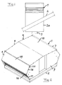
- a roof fan 1 according to a first embodiment of the invention is very schematically illustrated in Fig 1 , in which it is shown how this is arranged on a roof 2 of a building for transport of air from an exhaust air channel 3 connecting to different exhaust air members not shown inside the building to the exterior of the building.
- the roof fan 1 is in fact not arranged directly on the roof, but it is fixed to a roof lead-through member 2a. It is well possible that the roof fan is connected to only a short channel through the member 2a and no other exhaust air channel exists or that a plurality of exhaust air channels inside the building are connected to the member 2a. All these alternatives are intended to be covered by the wording of claim 1.
- the construction of this roof fan will now be described while making reference also to Figs 2-7 .
- the roof fan comprises a housing 4 having a bottom 5, the size of which being adapted to the size of the member 2a, two first opposite sides 6, 7 defined by walls extending from said bottom and two other, second opposite sides 8, 9 as well as a top side wall 10.
- a fan member 11 in the form of an impeller 12 having blades 13 curved backwards with respect to the rotation direction of the impeller and a motor 14 for rotation of the impeller is arranged inside the housing.
- the bottom 5 is provided with in inlet opening 15 (best seen in Fig 9 ) configured to be connected to a said exhaust air channel 3 for sucking air therefrom.
- the housing is provided with outlet openings 16 for exhausting air to the exterior only at the two opposite first sides 6, 7 thereof, whereas the other two opposite sides 8, 9 are closed and have no outlet opening.
- the distance between said opposite sides 6, 7 and 8, 9 of the housing is adapted for obtaining a high efficiency of the fan member. The distance may not be too small with respect to the diameter of the impeller for obtaining an optimum capacity.
- Each said first opposite side has a lower 17 and an upper 18 part extending from the bottom 5 and the top 10 of the housing, respectively, away from the other said opposite side. These two parts 17, 18 make an angle with each other of 90°-140°, preferably 100°-125°.
- Each said first opposite side is provided with a member 19 configured to cover a part of said side while leaving a part thereof open for airflow out of the housing. This member 19 is movably attached to the upper 18 or lower 17 part in the form of end surfaces of the respective part by screws 20 schematically indicated.
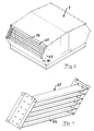
- this member 19 may be moved from a first position, in which it covers the lower part 17 of said side and allow exhausting air substantially upwards with respect to the bottom 5, to a second position shown in Fig 2 , in which it covers the upper part 18 of said side and causes exhausting of air substantially horizontally or downwards with respect to said bottom.
- the first position is shown in Fig 3 .
- Fig 4 illustrates a grill 21 having fins or ribs 22 and configured to be moved upon said conversion to cover the part of the respective side not covered by the covering member 19. It is shown how this grill is also fixed by screws 23 to the lateral walls 8, 9.
- the fins 22 of the grill are configured to guide air exhausted through said outlet opening substantially upwards or substantially horizontally or downwards depending upon the position of said covering member 19 and by that the grill.
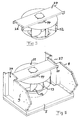
- Figs 5 and 6 illustrate how the impeller 12 and motor 14 are suspended in a plate member 24 fixed to opposite sides 8, 9 of said housing having no said outlet opening. This is done by screws as indicated at 25, and opposite end surfaces 26 of the plate member are configured to bear against a part of the internal lateral wall of the respective side 8, 9 of the housing making the suspension of the impeller with motor very stable with respect to movement in the longitudinal direction of the plate member, i.e. from one of the sides 8, 9 to the other. Further screws 34 secure said end surfaces 26 of the plate to the respective lateral wall 8, 9 making said suspension stable in the transversal direction of the plate.
- outlet openings are only arranged on two opposite sides of the housing it will also be very easy to arrange a sound insulating layer 29a in a roof fan according to the invention by introducing this between said plate member and the top side wall 10 of the housing as well as a sound insulating layer 29b inside the respective lateral wall 8, 9 on both sides of said recess 27 for reducing noise coming from the operation of the fan member.
- Extra support members 30, 31 are for this sake fixed inside the housing for holding said insulating layer laterally.
- the arrangement of said sound insulating layer may reduce the level of said noise in the order of 4-5 dB.
- the roof fan also comprises a member configure to pivotally connect the housing 4 to a roof (in fact a roof lead-through member) for allowing access to said exhaust air channel of the building, and two different ways of obtaining this are illustrated in Fig 8 and 9 .
- Fig 8 illustrates how a connecting member 32 includes the bottom 5 of the housing configured to be fixed to a said roof lead-through member and by that onto a said roof, and the rest of the housing is pivotally connected to the bottom.
- Fig 9 illustrates how the connecting member comprises a frame 33 configured to be fixed to a said roof lead-through member, and the entire housing is pivotally connected to said frame.
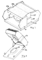
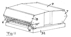
- Figs 10 and 11 illustrate a roof fan according to a second embodiment of the invention, in which the grill 21' has no guiding fins but only members there for forming an obstacle to items, such as birds, to enter into the housing. It is shown how this grill 21' may then be fixed to the housing by screws in the same way as the covering member 19. It is in this embodiment also possible, although not clearly shown in the figures, to make the grill 21' and covering member 19 in one part configured to be turned approximately 180° for obtaining said conversion between the position according to Fig 10 and the one according to Fig 11 .
Landscapes
- Engineering & Computer Science (AREA)
- Mechanical Engineering (AREA)
- General Engineering & Computer Science (AREA)
- Chemical & Material Sciences (AREA)
- Combustion & Propulsion (AREA)
- Structures Of Non-Positive Displacement Pumps (AREA)
- Ventilation (AREA)
Priority Applications (2)
| Application Number | Priority Date | Filing Date | Title |
|---|---|---|---|
| EP08170376A EP2192306B1 (de) | 2008-12-01 | 2008-12-01 | Dachlüfter |
| AT08170376T ATE523694T1 (de) | 2008-12-01 | 2008-12-01 | Dachlüfter |
Applications Claiming Priority (1)
| Application Number | Priority Date | Filing Date | Title |
|---|---|---|---|
| EP08170376A EP2192306B1 (de) | 2008-12-01 | 2008-12-01 | Dachlüfter |
Publications (2)
| Publication Number | Publication Date |
|---|---|
| EP2192306A1 true EP2192306A1 (de) | 2010-06-02 |
| EP2192306B1 EP2192306B1 (de) | 2011-09-07 |
Family
ID=40532552
Family Applications (1)
| Application Number | Title | Priority Date | Filing Date |
|---|---|---|---|
| EP08170376A Not-in-force EP2192306B1 (de) | 2008-12-01 | 2008-12-01 | Dachlüfter |
Country Status (2)
| Country | Link |
|---|---|
| EP (1) | EP2192306B1 (de) |
| AT (1) | ATE523694T1 (de) |
Cited By (1)
| Publication number | Priority date | Publication date | Assignee | Title |
|---|---|---|---|---|
| EP4343154A1 (de) * | 2022-09-21 | 2024-03-27 | ebm-papst Mulfingen GmbH & Co. KG | Radialventilator mit nachrüstbaren luftleitsegmenten |
Citations (4)
| Publication number | Priority date | Publication date | Assignee | Title |
|---|---|---|---|---|
| US3946648A (en) * | 1972-02-28 | 1976-03-30 | Buttner-Schilde-Haas Aktiengesellschaft | Roof ventilator |
| GB1512294A (en) * | 1974-12-16 | 1978-06-01 | Friedling G | Ventilator |
| JPS5820998A (ja) * | 1981-07-30 | 1983-02-07 | Shimizu Constr Co Ltd | ル−フフアン |
| GB2213926A (en) * | 1984-10-23 | 1989-08-23 | Gebhardt Gmbh Wilhelm | Roof ventilator |
-
2008
- 2008-12-01 AT AT08170376T patent/ATE523694T1/de not_active IP Right Cessation
- 2008-12-01 EP EP08170376A patent/EP2192306B1/de not_active Not-in-force
Patent Citations (4)
| Publication number | Priority date | Publication date | Assignee | Title |
|---|---|---|---|---|
| US3946648A (en) * | 1972-02-28 | 1976-03-30 | Buttner-Schilde-Haas Aktiengesellschaft | Roof ventilator |
| GB1512294A (en) * | 1974-12-16 | 1978-06-01 | Friedling G | Ventilator |
| JPS5820998A (ja) * | 1981-07-30 | 1983-02-07 | Shimizu Constr Co Ltd | ル−フフアン |
| GB2213926A (en) * | 1984-10-23 | 1989-08-23 | Gebhardt Gmbh Wilhelm | Roof ventilator |
Cited By (1)
| Publication number | Priority date | Publication date | Assignee | Title |
|---|---|---|---|---|
| EP4343154A1 (de) * | 2022-09-21 | 2024-03-27 | ebm-papst Mulfingen GmbH & Co. KG | Radialventilator mit nachrüstbaren luftleitsegmenten |
Also Published As
| Publication number | Publication date |
|---|---|
| ATE523694T1 (de) | 2011-09-15 |
| EP2192306B1 (de) | 2011-09-07 |
Similar Documents
| Publication | Publication Date | Title |
|---|---|---|
| CA2764725C (en) | Snow proof roof vent | |
| US20130130611A1 (en) | Outdoor air conditioner cover assembly | |
| US20140011440A1 (en) | Vent cover | |
| JP5196166B2 (ja) | 空気調和機の室外機 | |
| CN110012642A (zh) | 通风散热装置及机电设备 | |
| US20100021294A1 (en) | Fan structure for mounting in a light steel structure of a ceiling | |
| KR101770422B1 (ko) | 안티 아이싱 루버 | |
| CA2531538A1 (en) | Ventilation system | |
| KR101650811B1 (ko) | 리노베이션 건물의 에너지절약 외피통풍구조 | |
| EP2192306B1 (de) | Dachlüfter | |
| JP6499009B2 (ja) | 換気フード | |
| US20210140676A1 (en) | Air outlet structure and air conditioner having same | |
| KR100976704B1 (ko) | 고정식 환기구 | |
| KR101435007B1 (ko) | 소음 저감형 루버 | |
| KR20130060680A (ko) | 창틀일체형 프레임을 구비한 이중외피 커튼월 | |
| CN211261220U (zh) | 接水盘和窗式空调器 | |
| JP5498263B2 (ja) | 建物の床下換気構造 | |
| KR200449441Y1 (ko) | 루프팬 환기장치 | |
| CA2559641C (en) | Solar air heating system | |
| CN107002455B (zh) | 通风格栅 | |
| JP4805041B2 (ja) | 換気扇 | |
| JP3219089U (ja) | エアコンの室外機用カバー | |
| JP5882184B2 (ja) | 建物 | |
| JP2010060198A (ja) | 調湿ルーバー | |
| KR102623118B1 (ko) | 자연환기를 위한 비닐하우스 상부 환기 장치 |
Legal Events
| Date | Code | Title | Description |
|---|---|---|---|
| PUAI | Public reference made under article 153(3) epc to a published international application that has entered the european phase |
Free format text: ORIGINAL CODE: 0009012 |
|
| AK | Designated contracting states |
Kind code of ref document: A1 Designated state(s): AT BE BG CH CY CZ DE DK EE ES FI FR GB GR HR HU IE IS IT LI LT LU LV MC MT NL NO PL PT RO SE SI SK TR |
|
| AX | Request for extension of the european patent |
Extension state: AL BA MK RS |
|
| 17P | Request for examination filed |
Effective date: 20101129 |
|
| GRAP | Despatch of communication of intention to grant a patent |
Free format text: ORIGINAL CODE: EPIDOSNIGR1 |
|
| AKX | Designation fees paid |
Designated state(s): AT BE BG CH CY CZ DE DK EE ES FI FR GB GR HR HU IE IS IT LI LT LU LV MC MT NL NO PL PT RO SE SI SK TR |
|
| GRAS | Grant fee paid |
Free format text: ORIGINAL CODE: EPIDOSNIGR3 |
|
| GRAA | (expected) grant |
Free format text: ORIGINAL CODE: 0009210 |
|
| REG | Reference to a national code |
Ref country code: GB Ref legal event code: FG4D |
|
| REG | Reference to a national code |
Ref country code: CH Ref legal event code: EP |
|
| REG | Reference to a national code |
Ref country code: IE Ref legal event code: FG4D |
|
| REG | Reference to a national code |
Ref country code: DE Ref legal event code: R096 Ref document number: 602008009511 Country of ref document: DE Effective date: 20111103 |
|
| REG | Reference to a national code |
Ref country code: SE Ref legal event code: TRGR |
|
| REG | Reference to a national code |
Ref country code: NL Ref legal event code: VDEP Effective date: 20110907 |
|
| PG25 | Lapsed in a contracting state [announced via postgrant information from national office to epo] |
Ref country code: NO Free format text: LAPSE BECAUSE OF FAILURE TO SUBMIT A TRANSLATION OF THE DESCRIPTION OR TO PAY THE FEE WITHIN THE PRESCRIBED TIME-LIMIT Effective date: 20111207 Ref country code: FI Free format text: LAPSE BECAUSE OF FAILURE TO SUBMIT A TRANSLATION OF THE DESCRIPTION OR TO PAY THE FEE WITHIN THE PRESCRIBED TIME-LIMIT Effective date: 20110907 Ref country code: LT Free format text: LAPSE BECAUSE OF FAILURE TO SUBMIT A TRANSLATION OF THE DESCRIPTION OR TO PAY THE FEE WITHIN THE PRESCRIBED TIME-LIMIT Effective date: 20110907 Ref country code: HR Free format text: LAPSE BECAUSE OF FAILURE TO SUBMIT A TRANSLATION OF THE DESCRIPTION OR TO PAY THE FEE WITHIN THE PRESCRIBED TIME-LIMIT Effective date: 20110907 |
|
| LTIE | Lt: invalidation of european patent or patent extension |
Effective date: 20110907 |
|
| PG25 | Lapsed in a contracting state [announced via postgrant information from national office to epo] |
Ref country code: SI Free format text: LAPSE BECAUSE OF FAILURE TO SUBMIT A TRANSLATION OF THE DESCRIPTION OR TO PAY THE FEE WITHIN THE PRESCRIBED TIME-LIMIT Effective date: 20110907 Ref country code: GR Free format text: LAPSE BECAUSE OF FAILURE TO SUBMIT A TRANSLATION OF THE DESCRIPTION OR TO PAY THE FEE WITHIN THE PRESCRIBED TIME-LIMIT Effective date: 20111208 Ref country code: LV Free format text: LAPSE BECAUSE OF FAILURE TO SUBMIT A TRANSLATION OF THE DESCRIPTION OR TO PAY THE FEE WITHIN THE PRESCRIBED TIME-LIMIT Effective date: 20110907 Ref country code: AT Free format text: LAPSE BECAUSE OF FAILURE TO SUBMIT A TRANSLATION OF THE DESCRIPTION OR TO PAY THE FEE WITHIN THE PRESCRIBED TIME-LIMIT Effective date: 20110907 Ref country code: CY Free format text: LAPSE BECAUSE OF FAILURE TO SUBMIT A TRANSLATION OF THE DESCRIPTION OR TO PAY THE FEE WITHIN THE PRESCRIBED TIME-LIMIT Effective date: 20110907 |
|
| REG | Reference to a national code |
Ref country code: AT Ref legal event code: MK05 Ref document number: 523694 Country of ref document: AT Kind code of ref document: T Effective date: 20110907 |
|
| PG25 | Lapsed in a contracting state [announced via postgrant information from national office to epo] |
Ref country code: BE Free format text: LAPSE BECAUSE OF FAILURE TO SUBMIT A TRANSLATION OF THE DESCRIPTION OR TO PAY THE FEE WITHIN THE PRESCRIBED TIME-LIMIT Effective date: 20110907 |
|
| PG25 | Lapsed in a contracting state [announced via postgrant information from national office to epo] |
Ref country code: IS Free format text: LAPSE BECAUSE OF FAILURE TO SUBMIT A TRANSLATION OF THE DESCRIPTION OR TO PAY THE FEE WITHIN THE PRESCRIBED TIME-LIMIT Effective date: 20120107 Ref country code: CZ Free format text: LAPSE BECAUSE OF FAILURE TO SUBMIT A TRANSLATION OF THE DESCRIPTION OR TO PAY THE FEE WITHIN THE PRESCRIBED TIME-LIMIT Effective date: 20110907 Ref country code: SK Free format text: LAPSE BECAUSE OF FAILURE TO SUBMIT A TRANSLATION OF THE DESCRIPTION OR TO PAY THE FEE WITHIN THE PRESCRIBED TIME-LIMIT Effective date: 20110907 |
|
| PG25 | Lapsed in a contracting state [announced via postgrant information from national office to epo] |
Ref country code: PT Free format text: LAPSE BECAUSE OF FAILURE TO SUBMIT A TRANSLATION OF THE DESCRIPTION OR TO PAY THE FEE WITHIN THE PRESCRIBED TIME-LIMIT Effective date: 20120109 Ref country code: IT Free format text: LAPSE BECAUSE OF FAILURE TO SUBMIT A TRANSLATION OF THE DESCRIPTION OR TO PAY THE FEE WITHIN THE PRESCRIBED TIME-LIMIT Effective date: 20110907 Ref country code: RO Free format text: LAPSE BECAUSE OF FAILURE TO SUBMIT A TRANSLATION OF THE DESCRIPTION OR TO PAY THE FEE WITHIN THE PRESCRIBED TIME-LIMIT Effective date: 20110907 Ref country code: EE Free format text: LAPSE BECAUSE OF FAILURE TO SUBMIT A TRANSLATION OF THE DESCRIPTION OR TO PAY THE FEE WITHIN THE PRESCRIBED TIME-LIMIT Effective date: 20110907 Ref country code: PL Free format text: LAPSE BECAUSE OF FAILURE TO SUBMIT A TRANSLATION OF THE DESCRIPTION OR TO PAY THE FEE WITHIN THE PRESCRIBED TIME-LIMIT Effective date: 20110907 Ref country code: NL Free format text: LAPSE BECAUSE OF FAILURE TO SUBMIT A TRANSLATION OF THE DESCRIPTION OR TO PAY THE FEE WITHIN THE PRESCRIBED TIME-LIMIT Effective date: 20110907 |
|
| PLBE | No opposition filed within time limit |
Free format text: ORIGINAL CODE: 0009261 |
|
| STAA | Information on the status of an ep patent application or granted ep patent |
Free format text: STATUS: NO OPPOSITION FILED WITHIN TIME LIMIT |
|
| PG25 | Lapsed in a contracting state [announced via postgrant information from national office to epo] |
Ref country code: MC Free format text: LAPSE BECAUSE OF NON-PAYMENT OF DUE FEES Effective date: 20111231 Ref country code: DK Free format text: LAPSE BECAUSE OF FAILURE TO SUBMIT A TRANSLATION OF THE DESCRIPTION OR TO PAY THE FEE WITHIN THE PRESCRIBED TIME-LIMIT Effective date: 20110907 |
|
| 26N | No opposition filed |
Effective date: 20120611 |
|
| REG | Reference to a national code |
Ref country code: FR Ref legal event code: ST Effective date: 20120831 |
|
| REG | Reference to a national code |
Ref country code: IE Ref legal event code: MM4A |
|
| REG | Reference to a national code |
Ref country code: DE Ref legal event code: R097 Ref document number: 602008009511 Country of ref document: DE Effective date: 20120611 |
|
| PG25 | Lapsed in a contracting state [announced via postgrant information from national office to epo] |
Ref country code: IE Free format text: LAPSE BECAUSE OF NON-PAYMENT OF DUE FEES Effective date: 20111201 |
|
| PG25 | Lapsed in a contracting state [announced via postgrant information from national office to epo] |
Ref country code: MT Free format text: LAPSE BECAUSE OF FAILURE TO SUBMIT A TRANSLATION OF THE DESCRIPTION OR TO PAY THE FEE WITHIN THE PRESCRIBED TIME-LIMIT Effective date: 20110907 |
|
| PG25 | Lapsed in a contracting state [announced via postgrant information from national office to epo] |
Ref country code: FR Free format text: LAPSE BECAUSE OF NON-PAYMENT OF DUE FEES Effective date: 20120102 Ref country code: ES Free format text: LAPSE BECAUSE OF FAILURE TO SUBMIT A TRANSLATION OF THE DESCRIPTION OR TO PAY THE FEE WITHIN THE PRESCRIBED TIME-LIMIT Effective date: 20111218 |
|
| PG25 | Lapsed in a contracting state [announced via postgrant information from national office to epo] |
Ref country code: LU Free format text: LAPSE BECAUSE OF NON-PAYMENT OF DUE FEES Effective date: 20111201 |
|
| PG25 | Lapsed in a contracting state [announced via postgrant information from national office to epo] |
Ref country code: BG Free format text: LAPSE BECAUSE OF FAILURE TO SUBMIT A TRANSLATION OF THE DESCRIPTION OR TO PAY THE FEE WITHIN THE PRESCRIBED TIME-LIMIT Effective date: 20111207 |
|
| REG | Reference to a national code |
Ref country code: CH Ref legal event code: PL |
|
| GBPC | Gb: european patent ceased through non-payment of renewal fee |
Effective date: 20121201 |
|
| PG25 | Lapsed in a contracting state [announced via postgrant information from national office to epo] |
Ref country code: TR Free format text: LAPSE BECAUSE OF FAILURE TO SUBMIT A TRANSLATION OF THE DESCRIPTION OR TO PAY THE FEE WITHIN THE PRESCRIBED TIME-LIMIT Effective date: 20110907 |
|
| PG25 | Lapsed in a contracting state [announced via postgrant information from national office to epo] |
Ref country code: LI Free format text: LAPSE BECAUSE OF NON-PAYMENT OF DUE FEES Effective date: 20121231 Ref country code: CH Free format text: LAPSE BECAUSE OF NON-PAYMENT OF DUE FEES Effective date: 20121231 Ref country code: HU Free format text: LAPSE BECAUSE OF FAILURE TO SUBMIT A TRANSLATION OF THE DESCRIPTION OR TO PAY THE FEE WITHIN THE PRESCRIBED TIME-LIMIT Effective date: 20110907 |
|
| PG25 | Lapsed in a contracting state [announced via postgrant information from national office to epo] |
Ref country code: GB Free format text: LAPSE BECAUSE OF NON-PAYMENT OF DUE FEES Effective date: 20121201 |
|
| PGFP | Annual fee paid to national office [announced via postgrant information from national office to epo] |
Ref country code: SE Payment date: 20131219 Year of fee payment: 6 Ref country code: DE Payment date: 20131220 Year of fee payment: 6 |
|
| PG25 | Lapsed in a contracting state [announced via postgrant information from national office to epo] |
Ref country code: SE Free format text: LAPSE BECAUSE OF NON-PAYMENT OF DUE FEES Effective date: 20141202 |
|
| REG | Reference to a national code |
Ref country code: SE Ref legal event code: EUG |
|
| PG25 | Lapsed in a contracting state [announced via postgrant information from national office to epo] |
Ref country code: DE Free format text: LAPSE BECAUSE OF NON-PAYMENT OF DUE FEES Effective date: 20150701 |