EP2192310A2 - Crochet de mousqueton - Google Patents
Crochet de mousqueton Download PDFInfo
- Publication number
- EP2192310A2 EP2192310A2 EP09014350A EP09014350A EP2192310A2 EP 2192310 A2 EP2192310 A2 EP 2192310A2 EP 09014350 A EP09014350 A EP 09014350A EP 09014350 A EP09014350 A EP 09014350A EP 2192310 A2 EP2192310 A2 EP 2192310A2
- Authority
- EP
- European Patent Office
- Prior art keywords
- closure part
- blocking
- pivoting
- bracket
- blocking element
- Prior art date
- Legal status (The legal status is an assumption and is not a legal conclusion. Google has not performed a legal analysis and makes no representation as to the accuracy of the status listed.)
- Granted
Links
Images



Classifications
-
- F—MECHANICAL ENGINEERING; LIGHTING; HEATING; WEAPONS; BLASTING
- F16—ENGINEERING ELEMENTS AND UNITS; GENERAL MEASURES FOR PRODUCING AND MAINTAINING EFFECTIVE FUNCTIONING OF MACHINES OR INSTALLATIONS; THERMAL INSULATION IN GENERAL
- F16B—DEVICES FOR FASTENING OR SECURING CONSTRUCTIONAL ELEMENTS OR MACHINE PARTS TOGETHER, e.g. NAILS, BOLTS, CIRCLIPS, CLAMPS, CLIPS OR WEDGES; JOINTS OR JOINTING
- F16B45/00—Hooks; Eyes
- F16B45/02—Hooks with pivoting or elastically bending closing member
- F16B45/027—Hooks with pivoting or elastically bending closing member and having position-locking means for the closing member
- F16B45/028—Hooks with pivoting or elastically bending closing member and having position-locking means for the closing member the position-locking means being pivotally connected
-
- F—MECHANICAL ENGINEERING; LIGHTING; HEATING; WEAPONS; BLASTING
- F16—ENGINEERING ELEMENTS AND UNITS; GENERAL MEASURES FOR PRODUCING AND MAINTAINING EFFECTIVE FUNCTIONING OF MACHINES OR INSTALLATIONS; THERMAL INSULATION IN GENERAL
- F16B—DEVICES FOR FASTENING OR SECURING CONSTRUCTIONAL ELEMENTS OR MACHINE PARTS TOGETHER, e.g. NAILS, BOLTS, CIRCLIPS, CLAMPS, CLIPS OR WEDGES; JOINTS OR JOINTING
- F16B45/00—Hooks; Eyes
- F16B45/02—Hooks with pivoting or elastically bending closing member
- F16B45/023—Hooks with pivoting or elastically bending closing member the closing member pivoting about an axis perpendicular to the plane of the hook
-
- F—MECHANICAL ENGINEERING; LIGHTING; HEATING; WEAPONS; BLASTING
- F16—ENGINEERING ELEMENTS AND UNITS; GENERAL MEASURES FOR PRODUCING AND MAINTAINING EFFECTIVE FUNCTIONING OF MACHINES OR INSTALLATIONS; THERMAL INSULATION IN GENERAL
- F16B—DEVICES FOR FASTENING OR SECURING CONSTRUCTIONAL ELEMENTS OR MACHINE PARTS TOGETHER, e.g. NAILS, BOLTS, CIRCLIPS, CLAMPS, CLIPS OR WEDGES; JOINTS OR JOINTING
- F16B45/00—Hooks; Eyes
- F16B45/02—Hooks with pivoting or elastically bending closing member
- F16B45/024—Hooks with pivoting or elastically bending closing member and having means biasing the closing member about the pivot
- F16B45/026—Hooks with pivoting or elastically bending closing member and having means biasing the closing member about the pivot and including a coil type spring
Definitions
- the present invention relates to a snap hook with at least one bracket and at least one closure part and at least one insertion opening of the bracket, which is closed by the closure member in its closed position, wherein the closure member is pivotally mounted by means of a VerInstitutteilschwenkachse between the closed position and a maximum open position on the bracket and at least one blocking element is mounted pivotably on or in the closure part by means of a blocking element pivot axis, the blocking element blocking the closure part in its closed position against pivoting of the closure part towards its maximally open position in at least one blocking position and pivoting the closure part in at least one release position towards the maximum open position allowed.
- Snap hooks are used e.g. used in various sports such as climbing, ice climbing, mountaineering, paragliding, hang gliding and the like in various embodiments and for various purposes. They are also used to protect working persons against falling.
- the hanger of the snap hook is hooked into a rope, an eyelet or the like.
- the rope or the eyelet is inserted through the insertion opening into the interior of the bracket. The insertion opening is opened by pivoting the closure part. If the rope or eyelet is inside the bracket, the insertion opening can be closed again by pivoting back the locking part.
- various safety measures are now known which are intended to prevent the closure part from being inadvertently pivoted into the open position when the carabiner hook is being used.
- a generic type of securing the closure part is from the first two embodiments of the WO 95/19505 known.
- a pivotable about a locking element pivot axis in the interior of the pivotable closure part Locking element stored. This has a handle and a support bar. In the locking position, the blocking element is in such a position that the support web rests against a support surface of the bracket. In this blocking position accidental pivoting of the closure part is prevented, the closure member is thus locked against pivoting in the direction of its maximum open position. By pressing on the handle, the blocking element pivots.
- the inner support bar engages out of engagement with the support surface of the bracket and the closure member can be pivoted about its closure member pivot axis in the direction of its maximum open position. When you release the closure part and the blocking element is a swinging back to the starting position by means of a return spring.
- the object of the invention is to provide a generic snap hook, which allows a large opening angle of the closure part, in which the blocking element in its blocking position the closure member but still securely locks against pivoting in the direction of the maximum open position of the closure member.
- the blocking element for releasing the closure part is pivoted in the same direction of rotation as the closure part pivots about the closure part pivot axis during pivoting out of the closed position in the direction of its maximum open position. It is thus envisaged that the blocking element from the blocking position in the direction of the release position and the closure part from the closed position in the direction towards its maximum open position both in the clockwise direction or both are to be pivoted counterclockwise accordingly. This avoids that, as in the prior art, by pivoting the blocking element to a limit of the maximum possible opening angle of the closure part comes through the handle of the blocking element. Furthermore, when the locking element according to the invention is pivoted, a greater torque is exerted on the closure part than in the prior art. This makes it possible to operate the locking element and the closure part simultaneously by a single movement of a single finger without much effort. This also allows safe and easy one-handed operation.
- the blocking element has a handle for actuating the blocking element and to push the handle for pivoting the blocking element from the blocking position in the direction towards the release position in a direction away from the closure part pivot axis or to pivot.
- the closure part has a recess and the handle, preferably the entire blocking element, is arranged within the exception.
- the handle and / or the entire locking element are completely within the recess, which means that neither the handle or other parts of the locking element project beyond the outer contours or the recess of the closure part. This preferably applies in all positions of the blocking element.
- Preferred embodiments of carabiner according to the invention provide that the blocking element has a contact surface with which it bears against a support surface of the bracket. This support surface is conveniently arranged in an end region of the bracket, in which preferably also the closure part pivot axis of the closure part is arranged.
- the locking element when pivoting about the Sperrelementschwenkachse of the blocking position in the direction of the Release position and / or in the opposite direction with its contact surface, preferably without slippage, rolls on the support surface of the bracket.
- This rolling can also be provided only in part of the pivoting movement, preferably when pivoting about the Sperrelementschwenkachse from the blocking position in the direction towards the release position in the first part of the pivoting movement.
- the blocking element is not only pivoted by, in particular slip-free, rolling, but also moved along the support surface of the bracket relative to this. In these embodiments, it is thus not provided that the blocking element slips or slides past the support surface during pivoting, but instead a relative movement between the support surface and blocking element during pivoting of the blocking element is necessarily achieved.
- this can be used so that, as a result of this rolling of the contact surface on the support surface during pivoting of the blocking element from the blocking position in the direction of the release position, the closure member is forcibly pivoted from the direction of its closed position toward its maximum open position.
- the closure part is automatically pivoted in the direction of its maximum open position. It is thus sufficient to actuate the locking element to automatically pivot the closure member.
- this is also possible in the reverse direction, in that when the blocking element is pivoted from the release position in the direction of the blocking position, the closure part forcibly pivots out in the direction of its maximum open position in the direction of its closed position.
- an actuation of the blocking element thus automatically leads to a pivoting of the closure part.
- this is not provided as long as the blocking element is in a blocking position, since the blocking element would otherwise not perform its security function.
- the locking element must not prevent pivoting of the closure part not only in a single locking position. Rather, it can also be provided that the blocking element, starting from a first blocking position in different blocking positions in a first angular range of a pivoting angle about the Sperrelementschwenkachse this side of a limit angle locks the closure member in its closed position against pivoting of the closure member towards its maximum open position.
- the blocking element leaves the first angular range, then it can be provided that the blocking element in a second angular range beyond the critical angle upon pivoting of the closure part in the direction of its maximum open Position in the direction towards a maximum release position of the blocking element is also forcibly swung.
- the blocking element does not necessarily have to be actuated for further pivoting of the closure part. It can also be operated directly the closure part, in which case the blocking element is mitbetätigt in this second angular range by pivoting the closure member by it is automatically or forcibly mitgeschwenkt.
- the blocking element thus has several blocking positions not only in the first angular range on this side of the critical angle.
- the blocking element can occupy several release positions in the second angular range beyond the critical angle.
- the critical angle is at angles equal to or less than 10 °, measured between a first straight line connecting the Sperrelementsschwenkachse and the point of contact surface of the locking element with the greatest distance from Sperrelementschwenkachse and a second connecting straight line between the Sperrelementschwenkachse and the VerInstitutteilschwenkachse.
- the designation on this side of the limit angle comprises all pivoting angles of the blocking element which lie between the first blocking position of the blocking element and the critical angle.
- the term beyond the critical angle includes all pivot angles that lie on the opposite side of the critical angle.
- the first and the second connecting lines each extend through the centers of the respective pivot axis (s).
- the critical angle is usually on the side of the second connecting line, which points in the direction of the first blocking position.
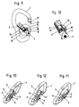
- Fig. 1 shows a side view of the snap hook according to the invention.
- the closure part 2 is pivotally mounted on the bracket 1 by means of the closure part pivot axis 4, in the Fig. 1 to 4 is the closure part 2 in its closed position in which the bracket 1 and the closure part 2 is a self-contained structure.
- the insertion opening 3 through which a rope or an eyelet or the like can be inserted into the interior of the bracket, completely closed.
- the Sperrelementschwenkachse 6 by which the locking element 5 can be pivoted to see.
- the blocking element 5 itself can not be seen, since it is arranged completely within a recess 9 in the closure part 2 and thus in the view according to FIG Fig. 1 behind which the recess bounding side walls of the closure part 2 is hidden. In this perspective, it is thus particularly easy to see that neither the handle 8, nor other parts of the blocking element 5 protrude from the recess 9.
- Fig. 2 now shows a view from the front on the snap hook.
- the recess 9 can be seen in the closure part 2.
- the blocking element 5 is arranged and also the return spring 13th Fig. 2 also shows the section line AA along the the closure part 2 and the blocking element 5 in the illustrations of Fig. 3 to 10 is cut.
- Fig. 4 shows area B Fig. 3 increased.
- the cut-off element 5 shown cut which is pivotally mounted about the Sperrelementschwenkachse 6 in the recess 9. It has the handle 8, which can be acted upon, for example with the thumb or another finger.
- the return spring 13 can be seen, which is provided in the shown embodiment, both for pivoting back of the closure part 2 in its closed position, as well as the blocking element 5 in its blocking position. It is thus a single common return spring 13. In other embodiments, of course, could also be provided separate return springs for closure member and locking element.
- the return spring 13 has, in the embodiment shown, a first leg 14 and at least one second leg 15. The first leg 14 is applied to the closure part 2, the second leg 15 on the locking element 5. In the area between the legs 14 and 15, the return spring 13 at the Block element pivot axis 6 stored. In the illustrated embodiment, it is wrapped around the Sperrelementschwenkachse 6 in this area. The Sperrelementschwenkachse 6 is fixedly attached to the closure part 2.
- the closure part pivot axis 4 is fixed in the embodiment shown fixed to the bracket 1, in the illustrated variant in the same end portion 12 of the bracket 1, in which this also has the support surface 11.
- the blocking element 5 is located with its contact surface 10 at.
- the blocking element 5 has, in a cross-section, a pin-like extension 18 whose outer surfaces have or at least partially form the contact surface 10.
- the contact surface 10 extends from one side of this pin 18, to the opposite side of the pin 18th
- Fig. 1 to 4 is the blocking element 5 in its first blocking position. It rests with a part of its contact surface 10 against an upper end region of the support surface 11 in such a way that, in an attempt to pivot the closure part 2 in the direction 19 of its maximum open position, the blocking element 5 prevents this pivoting movement and the closure part 2 thus locks in its closed position.
- the blocking effect results from the fact that in the attempt to pivot the closure part 2 in the direction 19, also the locking element pivot axis 6 fixedly arranged on the closure part 2 would have to be pivoted in the direction 19, which is due to the abutment of the contact surface 10 of the blocking element 5 on the support surface 11 of the bracket 1 but prevented.
- the support surface 11 is favorably, as realized here, a continuously curved surface. This means that it has no edges, which of course does not preclude that, as also shown in the embodiment shown, they may have a radius of curvature varying over their extension.
- the support surface 11 forms an outer surface of a wedge-shaped extension of the bracket 1, which points with its wedge tip in the direction towards the opposite end portion 20 of the bracket 1.
- the support surface 11 is arranged in the region between the blocking element pivot axis 6 and the closure part pivot axis 4.
- the closure part 2 in the Fig. 1 to 4 shown closed position must first the locking element 5 by pressing the handle 8 in a release position to be brought. This is done by the blocking element 5 is pivoted in the direction of rotation 7 about its blocking element pivot axis 6.
- the aforementioned direction of rotation 7 corresponds to the direction of rotation 7 in which the closure part 2 has to be pivoted about its closure part pivot axis 4 in order to be pivoted from the closed position in the direction of its maximum open position.
- FIGS. 5 and 6 Show now 3 and 4 analog sectional views, with the blocking element 5, however, is no longer in the first blocking position, but in the blocking angle corresponding to the limit position 16.
- the first angular range of the pivot angle of the locking element 5, in which the locking element 5 is still arranged in a blocking position is the first angular range of the pivot angle of the locking element 5, in which the locking element 5 is still arranged in a blocking position.
- the closure part 2 can still be in its closed position in all these positions of the blocking element 5 Fig. 1 are located. It is, however, as in the FIGS.
- the closure part 2 is already slightly swiveled in the direction of the 19 in the region of the critical angle 16, but conveniently the closure part 2 in the end region 20 still overlaps with the strap.
- this first angular range or in the blocking positions results in a force that tries to pivot the closure member 2 in the direction 19 so toward its maximum open position, by pressing the contact surface 10 to the support surface 11, either a torque on the blocking element, which in Direction whose first locking position acts or it is a torque on the locking element 5 in the opposite direction, ie generated in the direction of the release position, which is less than the static friction generated by the pressing of the contact surface 10 to the support surface 11.
- the desired blocking effect of the blocking element 5 is generated.
- Fig. 6 shows enlarged in Fig. 5 Area surrounded by a circle to explain the location of the critical angle 16.
- the point (or the line or the subarea) of the contact surface 10 with the greatest distance 24 from the blocking element pivot axis 6 or its center is denoted by the reference numeral 10a.
- the first connecting straight line 22 runs through this point 10a and the blocking element pivot axis 6 or its center.
- the second connecting straight line 23 extends between the blocking element pivot axis 6 or its center and the closure element axis 4 or its center.
- the distance between the center of the blocking element pivot axis 6 and the closure element pivot axis 4 is identified by the reference numeral 25.
- the critical angle 16 is measured between the first connecting line 22 and the second connecting line 23. It is in the illustrated embodiment about 8 ° and generally conveniently between 0 ° and 10 ° (inclusive).
- the first angle range on this side of the critical angle 16 lies between the first blocking position and the first connecting straight line 22 and is identified by the arrow 26. In this first angular range 26, the blocking element 5 is in each case in a blocking position.
- the second angle range beyond the critical angle 16 is located on the opposite side of the first connecting line 22 and is indicated by the arrow 27. In this second angular range, the blocking element 5 is in one of its release positions.
- the critical angle 16 is usually on the side of the second connecting line 23, which points in the direction 26 toward the first blocking position.
- the critical angle would be equal to 0 °, whereby the critical angle 16 would be reached when the point 10a on the second connecting line 23 to would come. In practice, however, for tolerance reasons allow a certain amount of play. However, this should be chosen so that the critical angle does not exceed 10 °. If there is no play, then there is a risk that the locking element 5 jammed with its contact surface 10 due to the wedge action against the support surface 11, which is usually only to be solved with considerable effort.
- the pivoting movement of the blocking element 5 from the first blocking position according to Fig. 1 to 4 , towards the threshold angle 16 according to Fig. 5 u 6 and continue towards the release position according to the Fig. 7 to 10 Rolls the blocking element 5 with its contact surface 10, preferably without slippage, on the support surface 11 of the bracket 1 from.
- the rolling first leads to a forced coupling of the pivoting movement of the locking element 5 about the Sperrelementschwenkachse 6 with a pivoting movement of the entire locking element 5 about the VerInstitutteilschwenkachse 4.
- the Fig. 7 u. 8 show an intermediate position in which the blocking element 5 is located at a pivoting angle in the second angular range above the limiting angle 16.
- the closure part 2 is in a partially open position, so that the insertion opening 3 is already partially released.
- the return spring 13 is located in a relation to the Fig. 3 to 6 further compressed state. It counteracts the pivoting movements in the direction of rotation 7 in all positions.
- Fig. 7 is the upper end portion 20 of the bracket 1 to see freely. He wears, as known per se, a bulge 17, which can be engaged behind by a corresponding shoulder 21 of the closure part 2. This serves, as is known, to increase the tensile strength of the snap hook when the closure part 2 is in the closed position.
- the user is free in the second angle range of the snap-in hook to attack the closure part 2 and the blocking element 5 on the handle 8 or directly on the closure part 2 for further pivoting.
- this second angular range both possible to the closure part 2 in the in the Fig. 9 u. 10 shown maximum open position to bring. If the handle 8 is actuated in the direction of rotation 7, a corresponding further opening of the closure part 2 takes place automatically via the unwinding of the blocking element 5 on the support surface 11. If, however, the closure part 2 is actuated directly, then in this second angular range the blocking element 5 automatically continues in the direction of rotation 7 pivoted about its Sperrelementschwenkachse 6. However, as already stated, the latter applies only to the second angle range above the limiting angle 16.
- the closure part 2 and the blocking element 5 can be easily released.
- the return spring 13 ensures by turning the locking element 5 against the direction 7 about its Sperrelementschwenkachse 6 automatically for a provision, wherein also in this provision, the contact surface 10 on the support surface 11 at least partially, preferably without slippage unrolls.
- Fig. 11 to 13 still show perspective views of the snap hook of this embodiment of the invention.
- Fig. 11 shows the position according to the Fig. 1 to 4 .
- Fig. 12 the position according to Fig. 7 u. 8 and Fig. 13 the position according to Fig. 9 u. 10. It can be seen particularly well in these illustrations that the recess 9 in the closure part 2 has a width such that the handle 8, which does not protrude beyond the recess 9, can be actuated with one finger.
- the Fig. 14 shows a side view of the blocking element 5, the Fig. 15 a perspective view.
- Fig . 14 are different points or areas 10a to 10d of the contact surface 10 of the blocking element 5 again labeled separately.
- the blocking element 5 lies with the region 10d on the in Fig. 6 marked surface 28 clearance.
- the surfaces in the region of the point 10a and the surface 10b roll off on the support surface 11 of the bracket 1, starting from the first blocking position.
- the blocking element 5 Up to the critical angle 16, the blocking element 5 is in each case in a blocking position in which the closure part 2 can not be further opened by directly acting on him force.
- the closure part 2 can be opened further by direct application of force.
- part of the area 10c rolls on the surface 11 of the bracket 1 and, during further opening, makes a sliding movement. With almost complete opening of the closure part 2, the area 10d still slides over the surface 11 of the bracket.
Landscapes
- Engineering & Computer Science (AREA)
- General Engineering & Computer Science (AREA)
- Mechanical Engineering (AREA)
- Hooks, Suction Cups, And Attachment By Adhesive Means (AREA)
- Emergency Lowering Means (AREA)
- Operating, Guiding And Securing Of Roll- Type Closing Members (AREA)
- Invalid Beds And Related Equipment (AREA)
- Refuge Islands, Traffic Blockers, Or Guard Fence (AREA)
Applications Claiming Priority (1)
| Application Number | Priority Date | Filing Date | Title |
|---|---|---|---|
| AT18502008 | 2008-11-27 |
Publications (3)
| Publication Number | Publication Date |
|---|---|
| EP2192310A2 true EP2192310A2 (fr) | 2010-06-02 |
| EP2192310A3 EP2192310A3 (fr) | 2015-06-24 |
| EP2192310B1 EP2192310B1 (fr) | 2018-05-09 |
Family
ID=42026839
Family Applications (1)
| Application Number | Title | Priority Date | Filing Date |
|---|---|---|---|
| EP09014350.4A Active EP2192310B1 (fr) | 2008-11-27 | 2009-11-17 | Crochet de mousqueton |
Country Status (5)
| Country | Link |
|---|---|
| US (1) | US8245369B2 (fr) |
| EP (1) | EP2192310B1 (fr) |
| AT (1) | AT11210U1 (fr) |
| CA (1) | CA2686428C (fr) |
| ES (1) | ES2674051T3 (fr) |
Cited By (1)
| Publication number | Priority date | Publication date | Assignee | Title |
|---|---|---|---|---|
| AT511336B1 (de) * | 2011-06-24 | 2012-11-15 | Aba Hoertnagl Gmbh | Karabinerhaken |
Families Citing this family (3)
| Publication number | Priority date | Publication date | Assignee | Title |
|---|---|---|---|---|
| FR2976638B1 (fr) * | 2011-06-16 | 2013-07-05 | Wichard | Mousqueton de securite |
| USD732937S1 (en) * | 2013-03-15 | 2015-06-30 | Kammok Holdings, Llc | Carabiner body |
| US9366043B2 (en) * | 2014-05-28 | 2016-06-14 | Mrm Hk Limited | Safety tether for a hand-held article |
Citations (1)
| Publication number | Priority date | Publication date | Assignee | Title |
|---|---|---|---|---|
| WO1995019505A1 (fr) | 1994-01-14 | 1995-07-20 | 'stubai' Werkzeugindustrie Registrierte Genossenschaft Mit Beschränkter Haftung | Mousqueton |
Family Cites Families (15)
| Publication number | Priority date | Publication date | Assignee | Title |
|---|---|---|---|---|
| US926156A (en) * | 1909-01-02 | 1909-06-29 | Rolla Waterhouse | Hook. |
| US1521811A (en) | 1923-08-06 | 1925-01-06 | Carl W Hartbauer | Snap hook |
| US1914189A (en) * | 1932-04-16 | 1933-06-13 | John C Yingling | Hook guard |
| US3114955A (en) * | 1960-05-20 | 1963-12-24 | Stallinefabriken | Arrangement in load hooks |
| US4050730A (en) * | 1976-05-19 | 1977-09-27 | Akio Tada | Hook latching device |
| US4122585A (en) * | 1977-07-18 | 1978-10-31 | Sharp Jonathan E | Single-action double-lock snap |
| US4440432A (en) * | 1982-02-22 | 1984-04-03 | The Crosby Group, Inc. | Self-locking, quick release, latched hook |
| US4528728A (en) * | 1982-10-13 | 1985-07-16 | Rose Manufacturing Company | Locking snap hook |
| EP0569059B1 (fr) | 1990-02-21 | 1996-11-20 | Stubai- Werkzeugindustrie Registrierte Genossenschaft Mit Beschränkter Haftung | Mousqueton |
| AT400976B (de) | 1994-01-14 | 1996-05-28 | Stubai Werkzeugind | Karabinerhaken |
| IT1310133B1 (it) * | 1999-07-21 | 2002-02-11 | Stefano Maruelli | Dispositivo di sicurezza ad aggancio rapido a moschettone con based'appoggio allargata e gancio ortogonale |
| US20030106190A1 (en) * | 2001-12-08 | 2003-06-12 | Tony Christianson | Button locking carabiner |
| DE102004017592B4 (de) * | 2004-04-07 | 2010-04-15 | Johnson Controls Gmbh | Vorrichtung zur Verriegelung und/oder zur Entriegelung einer Komponente, insbesondere in oder an einem Fahrzeug, und Verfahren |
| ATE453061T1 (de) * | 2006-06-26 | 2010-01-15 | Tony Christianson | Schnappverschlusskarabinerhaken |
| US7636990B1 (en) * | 2008-03-25 | 2009-12-29 | Gary E Choate | Snap hook with hoop-loaded gate |
-
2009
- 2009-11-13 AT AT0808109U patent/AT11210U1/de not_active IP Right Cessation
- 2009-11-17 ES ES09014350.4T patent/ES2674051T3/es active Active
- 2009-11-17 EP EP09014350.4A patent/EP2192310B1/fr active Active
- 2009-11-23 US US12/623,821 patent/US8245369B2/en active Active
- 2009-11-23 CA CA2686428A patent/CA2686428C/fr active Active
Patent Citations (1)
| Publication number | Priority date | Publication date | Assignee | Title |
|---|---|---|---|---|
| WO1995019505A1 (fr) | 1994-01-14 | 1995-07-20 | 'stubai' Werkzeugindustrie Registrierte Genossenschaft Mit Beschränkter Haftung | Mousqueton |
Cited By (2)
| Publication number | Priority date | Publication date | Assignee | Title |
|---|---|---|---|---|
| AT511336B1 (de) * | 2011-06-24 | 2012-11-15 | Aba Hoertnagl Gmbh | Karabinerhaken |
| AT511336A4 (de) * | 2011-06-24 | 2012-11-15 | Aba Hoertnagl Gmbh | Karabinerhaken |
Also Published As
| Publication number | Publication date |
|---|---|
| ES2674051T3 (es) | 2018-06-27 |
| CA2686428A1 (fr) | 2010-05-27 |
| EP2192310A3 (fr) | 2015-06-24 |
| CA2686428C (fr) | 2016-07-05 |
| US8245369B2 (en) | 2012-08-21 |
| EP2192310B1 (fr) | 2018-05-09 |
| US20100125985A1 (en) | 2010-05-27 |
| AT11210U1 (de) | 2010-06-15 |
Similar Documents
| Publication | Publication Date | Title |
|---|---|---|
| DE69616077T2 (de) | Sicherheitskarabinerhaken | |
| DE19829899B4 (de) | Reibschlüssige Gurteinstellvorrichtung | |
| EP1236543B1 (fr) | Pince étau ou pince extensible | |
| AT510436B1 (de) | Karabinerhaken | |
| EP1671009A1 (fr) | Appareil d'absorption faisant partie d'un absorbeur d'energie pour cables et elements d'ascension analogues | |
| WO2008046446A1 (fr) | Dispositif de blocage pour un système anti-chute | |
| DE112008001196T5 (de) | Führungsschiene für ein Schrank-Auszugsteil | |
| EP2956274B1 (fr) | Dispositif de blocage desserrable, en particulier sur un outil de serrage | |
| EP2248435B1 (fr) | Tendeur de sangle | |
| DE4237263C2 (de) | Karabinerhaken | |
| DE2733238C2 (fr) | ||
| EP2192310B1 (fr) | Crochet de mousqueton | |
| EP1229258B1 (fr) | Mousqueton constitué d'un corps muni d'une ouverture d'accès | |
| DE102015121669B4 (de) | Kartuschenpistole | |
| AT510061B1 (de) | Karabinerhaken | |
| DE202005011338U1 (de) | Auffanggerät für ein Steigschutzsystem | |
| DE19518493C2 (de) | Antriebseinrichtung für ein Torblatt | |
| DE202007014788U1 (de) | Lastbügel oder -haken | |
| EP2479443B1 (fr) | Dispositif de mousqueton | |
| DE102010014054A1 (de) | Öffnungshilfe für Energieführungsketten | |
| EP2085186A2 (fr) | Pince étau ou pince extensible | |
| EP2317164B1 (fr) | Crochet, notamment pour dispositifs de sécurité | |
| AT511336B1 (de) | Karabinerhaken | |
| EP1159987A2 (fr) | Frein de câble | |
| EP1656847B1 (fr) | Bande de maintien pour un article tel qu'une tétine ou une clé |
Legal Events
| Date | Code | Title | Description |
|---|---|---|---|
| PUAI | Public reference made under article 153(3) epc to a published international application that has entered the european phase |
Free format text: ORIGINAL CODE: 0009012 |
|
| AK | Designated contracting states |
Kind code of ref document: A2 Designated state(s): AT BE BG CH CY CZ DE DK EE ES FI FR GB GR HR HU IE IS IT LI LT LU LV MC MK MT NL NO PL PT RO SE SI SK SM TR |
|
| AX | Request for extension of the european patent |
Extension state: AL BA RS |
|
| RAP1 | Party data changed (applicant data changed or rights of an application transferred) |
Owner name: ABA HOERTNAGEL GMBH |
|
| PUAL | Search report despatched |
Free format text: ORIGINAL CODE: 0009013 |
|
| AK | Designated contracting states |
Kind code of ref document: A3 Designated state(s): AT BE BG CH CY CZ DE DK EE ES FI FR GB GR HR HU IE IS IT LI LT LU LV MC MK MT NL NO PL PT RO SE SI SK SM TR |
|
| AX | Request for extension of the european patent |
Extension state: AL BA RS |
|
| RIC1 | Information provided on ipc code assigned before grant |
Ipc: F16B 45/02 20060101AFI20150521BHEP |
|
| 17P | Request for examination filed |
Effective date: 20151113 |
|
| RBV | Designated contracting states (corrected) |
Designated state(s): AT BE BG CH CY CZ DE DK EE ES FI FR GB GR HR HU IE IS IT LI LT LU LV MC MK MT NL NO PL PT RO SE SI SK SM TR |
|
| GRAP | Despatch of communication of intention to grant a patent |
Free format text: ORIGINAL CODE: EPIDOSNIGR1 |
|
| INTG | Intention to grant announced |
Effective date: 20180202 |
|
| GRAS | Grant fee paid |
Free format text: ORIGINAL CODE: EPIDOSNIGR3 |
|
| GRAA | (expected) grant |
Free format text: ORIGINAL CODE: 0009210 |
|
| AK | Designated contracting states |
Kind code of ref document: B1 Designated state(s): AT BE BG CH CY CZ DE DK EE ES FI FR GB GR HR HU IE IS IT LI LT LU LV MC MK MT NL NO PL PT RO SE SI SK SM TR |
|
| REG | Reference to a national code |
Ref country code: GB Ref legal event code: FG4D Free format text: NOT ENGLISH |
|
| REG | Reference to a national code |
Ref country code: CH Ref legal event code: EP Ref country code: AT Ref legal event code: REF Ref document number: 997825 Country of ref document: AT Kind code of ref document: T Effective date: 20180515 |
|
| REG | Reference to a national code |
Ref country code: IE Ref legal event code: FG4D Free format text: LANGUAGE OF EP DOCUMENT: GERMAN |
|
| REG | Reference to a national code |
Ref country code: DE Ref legal event code: R096 Ref document number: 502009014944 Country of ref document: DE |
|
| REG | Reference to a national code |
Ref country code: ES Ref legal event code: FG2A Ref document number: 2674051 Country of ref document: ES Kind code of ref document: T3 Effective date: 20180627 |
|
| REG | Reference to a national code |
Ref country code: NL Ref legal event code: MP Effective date: 20180509 |
|
| REG | Reference to a national code |
Ref country code: LT Ref legal event code: MG4D |
|
| PG25 | Lapsed in a contracting state [announced via postgrant information from national office to epo] |
Ref country code: FI Free format text: LAPSE BECAUSE OF FAILURE TO SUBMIT A TRANSLATION OF THE DESCRIPTION OR TO PAY THE FEE WITHIN THE PRESCRIBED TIME-LIMIT Effective date: 20180509 Ref country code: BG Free format text: LAPSE BECAUSE OF FAILURE TO SUBMIT A TRANSLATION OF THE DESCRIPTION OR TO PAY THE FEE WITHIN THE PRESCRIBED TIME-LIMIT Effective date: 20180809 Ref country code: LT Free format text: LAPSE BECAUSE OF FAILURE TO SUBMIT A TRANSLATION OF THE DESCRIPTION OR TO PAY THE FEE WITHIN THE PRESCRIBED TIME-LIMIT Effective date: 20180509 Ref country code: SE Free format text: LAPSE BECAUSE OF FAILURE TO SUBMIT A TRANSLATION OF THE DESCRIPTION OR TO PAY THE FEE WITHIN THE PRESCRIBED TIME-LIMIT Effective date: 20180509 Ref country code: NO Free format text: LAPSE BECAUSE OF FAILURE TO SUBMIT A TRANSLATION OF THE DESCRIPTION OR TO PAY THE FEE WITHIN THE PRESCRIBED TIME-LIMIT Effective date: 20180809 |
|
| PG25 | Lapsed in a contracting state [announced via postgrant information from national office to epo] |
Ref country code: NL Free format text: LAPSE BECAUSE OF FAILURE TO SUBMIT A TRANSLATION OF THE DESCRIPTION OR TO PAY THE FEE WITHIN THE PRESCRIBED TIME-LIMIT Effective date: 20180509 Ref country code: HR Free format text: LAPSE BECAUSE OF FAILURE TO SUBMIT A TRANSLATION OF THE DESCRIPTION OR TO PAY THE FEE WITHIN THE PRESCRIBED TIME-LIMIT Effective date: 20180509 Ref country code: LV Free format text: LAPSE BECAUSE OF FAILURE TO SUBMIT A TRANSLATION OF THE DESCRIPTION OR TO PAY THE FEE WITHIN THE PRESCRIBED TIME-LIMIT Effective date: 20180509 Ref country code: GR Free format text: LAPSE BECAUSE OF FAILURE TO SUBMIT A TRANSLATION OF THE DESCRIPTION OR TO PAY THE FEE WITHIN THE PRESCRIBED TIME-LIMIT Effective date: 20180810 |
|
| PG25 | Lapsed in a contracting state [announced via postgrant information from national office to epo] |
Ref country code: EE Free format text: LAPSE BECAUSE OF FAILURE TO SUBMIT A TRANSLATION OF THE DESCRIPTION OR TO PAY THE FEE WITHIN THE PRESCRIBED TIME-LIMIT Effective date: 20180509 Ref country code: SK Free format text: LAPSE BECAUSE OF FAILURE TO SUBMIT A TRANSLATION OF THE DESCRIPTION OR TO PAY THE FEE WITHIN THE PRESCRIBED TIME-LIMIT Effective date: 20180509 Ref country code: PL Free format text: LAPSE BECAUSE OF FAILURE TO SUBMIT A TRANSLATION OF THE DESCRIPTION OR TO PAY THE FEE WITHIN THE PRESCRIBED TIME-LIMIT Effective date: 20180509 Ref country code: CZ Free format text: LAPSE BECAUSE OF FAILURE TO SUBMIT A TRANSLATION OF THE DESCRIPTION OR TO PAY THE FEE WITHIN THE PRESCRIBED TIME-LIMIT Effective date: 20180509 Ref country code: RO Free format text: LAPSE BECAUSE OF FAILURE TO SUBMIT A TRANSLATION OF THE DESCRIPTION OR TO PAY THE FEE WITHIN THE PRESCRIBED TIME-LIMIT Effective date: 20180509 Ref country code: DK Free format text: LAPSE BECAUSE OF FAILURE TO SUBMIT A TRANSLATION OF THE DESCRIPTION OR TO PAY THE FEE WITHIN THE PRESCRIBED TIME-LIMIT Effective date: 20180509 |
|
| REG | Reference to a national code |
Ref country code: DE Ref legal event code: R097 Ref document number: 502009014944 Country of ref document: DE |
|
| PG25 | Lapsed in a contracting state [announced via postgrant information from national office to epo] |
Ref country code: SM Free format text: LAPSE BECAUSE OF FAILURE TO SUBMIT A TRANSLATION OF THE DESCRIPTION OR TO PAY THE FEE WITHIN THE PRESCRIBED TIME-LIMIT Effective date: 20180509 |
|
| PLBE | No opposition filed within time limit |
Free format text: ORIGINAL CODE: 0009261 |
|
| STAA | Information on the status of an ep patent application or granted ep patent |
Free format text: STATUS: NO OPPOSITION FILED WITHIN TIME LIMIT |
|
| 26N | No opposition filed |
Effective date: 20190212 |
|
| PG25 | Lapsed in a contracting state [announced via postgrant information from national office to epo] |
Ref country code: SI Free format text: LAPSE BECAUSE OF FAILURE TO SUBMIT A TRANSLATION OF THE DESCRIPTION OR TO PAY THE FEE WITHIN THE PRESCRIBED TIME-LIMIT Effective date: 20180509 |
|
| REG | Reference to a national code |
Ref country code: CH Ref legal event code: PL |
|
| PG25 | Lapsed in a contracting state [announced via postgrant information from national office to epo] |
Ref country code: LU Free format text: LAPSE BECAUSE OF NON-PAYMENT OF DUE FEES Effective date: 20181117 Ref country code: MC Free format text: LAPSE BECAUSE OF FAILURE TO SUBMIT A TRANSLATION OF THE DESCRIPTION OR TO PAY THE FEE WITHIN THE PRESCRIBED TIME-LIMIT Effective date: 20180509 |
|
| REG | Reference to a national code |
Ref country code: BE Ref legal event code: MM Effective date: 20181130 |
|
| REG | Reference to a national code |
Ref country code: IE Ref legal event code: MM4A |
|
| PG25 | Lapsed in a contracting state [announced via postgrant information from national office to epo] |
Ref country code: LI Free format text: LAPSE BECAUSE OF NON-PAYMENT OF DUE FEES Effective date: 20181130 Ref country code: CH Free format text: LAPSE BECAUSE OF NON-PAYMENT OF DUE FEES Effective date: 20181130 |
|
| PG25 | Lapsed in a contracting state [announced via postgrant information from national office to epo] |
Ref country code: IE Free format text: LAPSE BECAUSE OF NON-PAYMENT OF DUE FEES Effective date: 20181117 |
|
| PG25 | Lapsed in a contracting state [announced via postgrant information from national office to epo] |
Ref country code: BE Free format text: LAPSE BECAUSE OF NON-PAYMENT OF DUE FEES Effective date: 20181130 |
|
| PG25 | Lapsed in a contracting state [announced via postgrant information from national office to epo] |
Ref country code: MT Free format text: LAPSE BECAUSE OF FAILURE TO SUBMIT A TRANSLATION OF THE DESCRIPTION OR TO PAY THE FEE WITHIN THE PRESCRIBED TIME-LIMIT Effective date: 20180509 |
|
| PG25 | Lapsed in a contracting state [announced via postgrant information from national office to epo] |
Ref country code: TR Free format text: LAPSE BECAUSE OF FAILURE TO SUBMIT A TRANSLATION OF THE DESCRIPTION OR TO PAY THE FEE WITHIN THE PRESCRIBED TIME-LIMIT Effective date: 20180509 |
|
| PG25 | Lapsed in a contracting state [announced via postgrant information from national office to epo] |
Ref country code: PT Free format text: LAPSE BECAUSE OF FAILURE TO SUBMIT A TRANSLATION OF THE DESCRIPTION OR TO PAY THE FEE WITHIN THE PRESCRIBED TIME-LIMIT Effective date: 20180509 |
|
| PG25 | Lapsed in a contracting state [announced via postgrant information from national office to epo] |
Ref country code: HU Free format text: LAPSE BECAUSE OF FAILURE TO SUBMIT A TRANSLATION OF THE DESCRIPTION OR TO PAY THE FEE WITHIN THE PRESCRIBED TIME-LIMIT; INVALID AB INITIO Effective date: 20091117 Ref country code: MK Free format text: LAPSE BECAUSE OF NON-PAYMENT OF DUE FEES Effective date: 20180509 Ref country code: CY Free format text: LAPSE BECAUSE OF FAILURE TO SUBMIT A TRANSLATION OF THE DESCRIPTION OR TO PAY THE FEE WITHIN THE PRESCRIBED TIME-LIMIT Effective date: 20180509 |
|
| PG25 | Lapsed in a contracting state [announced via postgrant information from national office to epo] |
Ref country code: IS Free format text: LAPSE BECAUSE OF FAILURE TO SUBMIT A TRANSLATION OF THE DESCRIPTION OR TO PAY THE FEE WITHIN THE PRESCRIBED TIME-LIMIT Effective date: 20180909 |
|
| PGFP | Annual fee paid to national office [announced via postgrant information from national office to epo] |
Ref country code: DE Payment date: 20251126 Year of fee payment: 17 |
|
| PGFP | Annual fee paid to national office [announced via postgrant information from national office to epo] |
Ref country code: GB Payment date: 20251125 Year of fee payment: 17 |
|
| PGFP | Annual fee paid to national office [announced via postgrant information from national office to epo] |
Ref country code: AT Payment date: 20251112 Year of fee payment: 17 |
|
| PGFP | Annual fee paid to national office [announced via postgrant information from national office to epo] |
Ref country code: IT Payment date: 20251121 Year of fee payment: 17 |
|
| PGFP | Annual fee paid to national office [announced via postgrant information from national office to epo] |
Ref country code: FR Payment date: 20251124 Year of fee payment: 17 |
|
| PGFP | Annual fee paid to national office [announced via postgrant information from national office to epo] |
Ref country code: ES Payment date: 20251209 Year of fee payment: 17 |