EP2192348A2 - Dispositif de ventilateur d'alimentation en air - Google Patents
Dispositif de ventilateur d'alimentation en air Download PDFInfo
- Publication number
- EP2192348A2 EP2192348A2 EP09177314A EP09177314A EP2192348A2 EP 2192348 A2 EP2192348 A2 EP 2192348A2 EP 09177314 A EP09177314 A EP 09177314A EP 09177314 A EP09177314 A EP 09177314A EP 2192348 A2 EP2192348 A2 EP 2192348A2
- Authority
- EP
- European Patent Office
- Prior art keywords
- air supply
- fan casing
- fan
- rotary shaft
- supply fan
- Prior art date
- Legal status (The legal status is an assumption and is not a legal conclusion. Google has not performed a legal analysis and makes no representation as to the accuracy of the status listed.)
- Withdrawn
Links
- 238000002485 combustion reaction Methods 0.000 claims abstract description 70
- 238000009423 ventilation Methods 0.000 claims abstract description 32
- 230000002093 peripheral effect Effects 0.000 claims abstract description 9
- XLYOFNOQVPJJNP-UHFFFAOYSA-N water Substances O XLYOFNOQVPJJNP-UHFFFAOYSA-N 0.000 description 8
- 238000001816 cooling Methods 0.000 description 3
- 238000007664 blowing Methods 0.000 description 1
- 230000001747 exhibiting effect Effects 0.000 description 1
- 230000004048 modification Effects 0.000 description 1
- 238000012986 modification Methods 0.000 description 1
Images



Classifications
-
- F—MECHANICAL ENGINEERING; LIGHTING; HEATING; WEAPONS; BLASTING
- F23—COMBUSTION APPARATUS; COMBUSTION PROCESSES
- F23L—SUPPLYING AIR OR NON-COMBUSTIBLE LIQUIDS OR GASES TO COMBUSTION APPARATUS IN GENERAL ; VALVES OR DAMPERS SPECIALLY ADAPTED FOR CONTROLLING AIR SUPPLY OR DRAUGHT IN COMBUSTION APPARATUS; INDUCING DRAUGHT IN COMBUSTION APPARATUS; TOPS FOR CHIMNEYS OR VENTILATING SHAFTS; TERMINALS FOR FLUES
- F23L5/00—Blast-producing apparatus before the fire
- F23L5/02—Arrangements of fans or blowers
-
- F—MECHANICAL ENGINEERING; LIGHTING; HEATING; WEAPONS; BLASTING
- F23—COMBUSTION APPARATUS; COMBUSTION PROCESSES
- F23N—REGULATING OR CONTROLLING COMBUSTION
- F23N3/00—Regulating air supply or draught
- F23N3/08—Regulating air supply or draught by power-assisted systems
-
- F—MECHANICAL ENGINEERING; LIGHTING; HEATING; WEAPONS; BLASTING
- F23—COMBUSTION APPARATUS; COMBUSTION PROCESSES
- F23N—REGULATING OR CONTROLLING COMBUSTION
- F23N2233/00—Ventilators
- F23N2233/06—Ventilators at the air intake
Definitions
- the present invention relates to an air supply fan device in a combustion apparatus and, more particularly, to an air supply fan device in which air-tightness is enhanced such that combustion exhaust gas staying inside of a combustion chamber cannot leak from the air supply fan device.
- a combustion apparatus for a water heater may be provided with an air supply fan device including an air supply fan in a combustion chamber containing a gas burner therein.
- an air supply fan device including an air supply fan in a combustion chamber containing a gas burner therein.
- a combustion apparatus of an FF type(forced draft balanced flue type) duplex supply/exhaust system in which a supply channel, through which outside air is supplied into a combustion chamber, and an exhaust channel, through which combustion exhaust gas staying in the combustion chamber is exhausted to the outside, are constituted of a single supply/exhaust cylinder, the outside air to be supplied is heated by the combustion exhaust gas, and therefore, the temperature of the motor rotary shaft is liable to be increased.
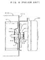
- a motor cooling ventilation hole 49 is formed in a fan casing constituting wall 411 around a motor rotary shaft 43 connected to an air supply fan device 41 inside of a fan casing 410, and further, a self-cooled fan 44, which projects by resiliency of a spring 47 during stoppage of rotation of a motor 42 so as to close the ventilation hole 49 ( FIG. 6 ) whereas retreats against the resiliency of the spring 47 during the rotation of the motor 42 so as to open the ventilation hole 49 ( FIG.
- reference numeral 45 designates a stopper, and further, 44b denotes a base for the self-cooled fan 44.
- the outer peripheral surface of the motor rotary shaft 43 and the inner circumferential edge of the ventilation hole 49 are not fully closed since there is a clearance k therebetween when the motor 42 is stopped from being rotated (see FIG. 6 ).
- the self-cooled fan 44 is urged by the spring 47, if an inner pressure inside of the combustion chamber is increased, the self-cooled fan 44 may retreat outward of the fan casing 410 (i.e., toward the motor 42) against the resiliency of the spring 47.
- an object of the present invention is to provide an air supply fan device, in which a motor rotary shaft or a motor can be securely cooled, and further, combustion exhaust gas can be prevented from leaking through a ventilation hole at the time of application of a positive pressure to a combustion chamber or a fan casing.
- An air supply fan device including: a fan casing disposed continuously to a combustion chamber containing a gas burner therein; an air supply fan contained inside of the fan casing, for supplying burning air to the gas burner; and a motor disposed outside of the fan casing, for rotating the air supply fan, the air supply fan device comprising:
- the valve body is made of a rubber sheet, and further, is formed into a projecting or recessed shape in such a manner as to enlarge a pressure receiving area of a pressure receiving portion which receives an air pressure inside of the fan casing.
- a pressure receiving portion is sensitive to a change in air pressure inside of the fan casing, so that the valve body is quickly deformed.
- the clearance is quickly defined, and therefore, the motor rotary shaft can be quickly cooled.
- the clearance is quickly closed, and therefore, the combustion exhaust gas hardly leaks.
- valve body is excellent in tightness of the peripheral edge of the through hole with respect to the motor rotary shaft owing to the property of a rubber sheet, thereby exhibiting high sealability, so as to more securely prevent the combustion exhaust gas from leaking through the ventilation hole.
- the inner diameter of the through hole is greater than the outer diameter of the motor rotary shaft, so as to define a clearance therebetween in the valve body when the inside and outside pressures of the fan casing are equal to each other.
- the motor rotary shaft cannot be brought into contact with the through hole of the valve body when the motor is started to be rotated.
- the valve body cannot be broken due to the rotation of the motor, or an extra load cannot be exerted on the rotation of the motor.
- the sealability of the valve body can be held for a long period of time when the pressure of the combustion chamber is positive.
- the motor rotary shaft or the motor can be securely cooled, and further, the combustion exhaust gas can be securely prevented from leaking through the ventilation hole when the positive pressure is applied to the combustion chamber or the fan casing.
- FIG. 1 is a view showing the entire configuration of a combustion apparatus (i.e., a water heater), to which an air supply fan device in a preferred embodiment according to the present invention is applied;
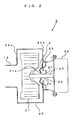
- FIG. 2 is a cross-sectional view showing the entire configuration of the air supply fan device;
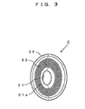
- FIG. 3 is a perspective view showing a valve body to be fixed to the air supply fan device.
- a water heater 1 serving as a combustion apparatus illustrated in FIG. 1 is designed for an FF type(forced draft balanced flue type) duplex supply/exhaust system including a supply/exhaust manifold 11 provided with a duplex pipe.
- a combustion chamber 14 containing a gas burner 15 and a heat exchanger 16 therein.
- An air supply fan device 2 is continuously disposed under the combustion chamber 14.
- the supply/exhaust manifold 11 is constituted of an inner pipe in a duplex pipe, that is, an exhaust cylinder 12 for allowing combustion exhaust gas to be exhausted from the combustion chamber 14 and an outer pipe, that is, a supply pipe 13 for taking air from the outside.
- the open end of the supply/exhaust manifold 11 is opened to the outside through a wall of a room, at which the water heater 1 is installed.
- the exhaust pipe 12 is connected to the upper portion of the combustion chamber 14, and constitutes an exhaust channel for exhausting the combustion exhaust gas from the combustion chamber 14 to the outside.
- the supply pipe 13 extends downward inside of the apparatus body 10, and the distal end thereof is continuously disposed in the air supply fan device 2 in an air-tight manner, thus constituting a supply channel for supplying outside air into the combustion chamber 14.
- the combustion chamber 14 and the supply/exhaust manifold 11 are connected to each other in an air-tight manner.
- the air supply fan device 2 includes: a fan casing 20 continuously disposed in the combustion chamber 14 in an air-tight manner; an air supply fan 21, or a sirocco fan housed inside of the fan casing 20, for supplying burning air to the gas burner 15; and a motor 22 disposed outside of the fan casing 20, for rotating the air supply fan 21.
- a fixing plate 25 for the motor 22 is securely attached to the outer surface of a constituting wall 24b opposite to the constituting wall 24a.
- the motor 22 is fixed to the fixing plate 25.
- a circular ventilation hole 26 is formed on the constituting wall 24b of the fan casing 20, onto which the motor 22 is fixed.
- a motor rotary shaft 23 for the motor 22 penetrates through the ventilation hole 26, and is connected to the air supply fan 21 housed inside of the fan casing 20.
- the inner diameter of the ventilation hole 26 is greater than the outer diameter of the motor rotary shaft 23. Therefore, an annular opening 27 is defined around the motor rotary shaft 23.
- a circular diaphragm valve body 3 is disposed around and in the ventilation hole 26.
- the valve body 3 is made of a circular rubber sheet having an outer diameter greater than that of the ventilation hole 26, and includes a through hole 31 opened at the center in such a manner as to allow the motor rotary shaft 23 to be inserted therethrough and a flange 32 extending outwards in such a manner as to be fixed onto the constituting wall 24b of the fan casing 20.
- the flange 32 is air-tightly attached to the inner surface of the constituting wall 24b of the fan casing 20 in the valve body 3 shown in FIG. 2 , it may be air-tightly attached to the outer surface of the constituting wall 24b.
- a peripheral edge 31a of the through hole 31 of the valve body 3 is formed in such a manner as to protrude toward the air supply fan 21 in a cylindrical shape.
- the inner diameter of the through hole 31 is slightly greater than the outer diameter of the motor rotary shaft 23, and therefore, a clearance 35 is defined therebetween. Therefore, the motor rotary shaft 23 cannot be brought into contact with the through hole 31 at the time of start of rotation of the motor 22 (pressure is equal inside and outside of the fan casing 20, see FIG. 2 ). Thus, it is possible to prevent the motor rotary shaft 23 from sliding in contact with the through hole 31 of the valve body 3 at the time of the start of the rotation of the motor 22.
- a region from the through hole 31 to the flange 32 in the valve body 3 serves as a pressure receiving portion 33 for receiving an air pressure inside of the fan casing 20.
- the pressure receiving portion 33 is expanded (projects) inward of the fan casing 20. In this manner, a greater pressure receiving area receiving the air pressure inside of the fan casing 20 can be provided, so that the valve body 3 can be quickly moved according to a change in air pressure inside of the fan casing 20.
- the pressure receiving portion 33 may be expanded (recessed) outward of the fan casing 20.
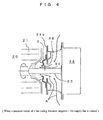
- the gas burner 15 in the combustion chamber 14 burns the air, and then, the air supply fan 21 is rotated, so that the outside air is supplied as the burning air from the air supply cylinder 13 into the combustion chamber 14 through the fan casing 20, thereby making the inner pressure of the fan casing 20 negative.
- the valve body 3 disposed in the ventilation hole 26 is deformed in such a manner as to be sucked inward of the fan casing 20, so that the diameter of the through hole 31 of the valve body 3 is increased.
- a gap 34 is defined between the through hole 31 of the valve body 3 and the motor rotary shaft 23.
- the valve body 3 is deformed in such a manner as to be pushed outside of the fan casing 20 by air flow B from the inside of the fan casing 20 toward the ventilation hole 26, as shown in FIG. 5 . And then, the diameter of the peripheral edge 31a of the through hole 31 projecting toward the air supply fan 21 in a cylindrical shape in the valve body 3 is reduced, the gap 34 between the through hole 31 and the motor rotary shaft 23 is closed in tight contact with the motor rotary shaft 23.
- the valve body 3 can exhibit a high sealability owing to excellent air-tightness of the peripheral edge 31a of the through hole 31 with respect to the motor rotary shaft 23 due to the properties of the rubber sheet, thus further securely preventing the combustion exhaust gas from leaking through the ventilation hole 26.
- the outside pressure of the air supply fan device 2 becomes negative by ventilating the room, at which the water heater 1 is installed, so that even if the air pressure inside of the combustion chamber 14 or the fan casing 20 becomes high (substantially, the pressure inside of the combustion chamber 14 or the fan casing 20 is positive), the valve body 3 is deformed to close the gap 34 defined between the through hole 31 and the motor rotary shaft 23, as shown in FIG. 5 .
- the motor rotary shaft 23 or the motor 22 can be effectively cooled when the air supply fan 21 is rotated.
- the combustion exhaust gas remaining inside of the combustion chamber 14 can be securely prevented from leaking through the ventilation hole 26 of the fan casing 20 even if the positive pressure is applied inside of the combustion chamber 14 or the fan casing 20.
- the inner diameter of the through hole 31 of the valve body 3 is greater than the outer diameter of the motor rotary shaft 23, thus defining the clearance 35.
- the motor rotary shaft 23 cannot be brought into contact with the through hole 31 of the valve body 3.
- the valve body 3 is made of the rubber sheet, and further, the pressure receiving portion 33 is formed into a projecting or recessed shape so as to enlarge the pressure receiving area, at which the air pressure inside of the fan casing 20 is received. Consequently, the valve body 3 sensitively reacts against the change in air pressure inside of the fan casing 20, to be deformed quickly. Therefore, when the inner pressure inside of the fan casing 20 becomes negative, the gap 34 is quickly defined, thereby quickly cooling the motor rotary shaft 23 or the like. In contrast, when the inner pressure inside of the fan casing 20 becomes positive, the gap 34 is quickly closed, thereby virtually preventing any leakage of the combustion exhaust gas.
- the air supply fan device 2 produces the following advantages. That is, the motor 22 can be fixed near the fan casing 20, thus configuring the compact air supply fan device 2; there is no problem of occurrence of noise in association with the rotation of the self-cooled fan; no extra load for rotating the self-cooled fan is exerted on the motor 22; and cost need not be increased since no self-cooled fan is provided.
- the outline shape of the valve body 3 or the shape of the ventilation hole 26 is not limited to a circle, but may be a polygon such as a square.
- the air supply fan device 2 is not limited to the water heater, but may be applied to a combustion apparatus for a heater or appliances other than the combustion apparatus of the FF type(forced draft balanced flue type) duplex supply/exhaust system.
Landscapes
- Engineering & Computer Science (AREA)
- Chemical & Material Sciences (AREA)
- Combustion & Propulsion (AREA)
- Mechanical Engineering (AREA)
- General Engineering & Computer Science (AREA)
- Structures Of Non-Positive Displacement Pumps (AREA)
- Air Supply (AREA)
- Regulation And Control Of Combustion (AREA)
Applications Claiming Priority (1)
| Application Number | Priority Date | Filing Date | Title |
|---|---|---|---|
| JP2008304785A JP2010127236A (ja) | 2008-11-28 | 2008-11-28 | 給気ファン装置 |
Publications (2)
| Publication Number | Publication Date |
|---|---|
| EP2192348A2 true EP2192348A2 (fr) | 2010-06-02 |
| EP2192348A3 EP2192348A3 (fr) | 2012-08-01 |
Family
ID=41720610
Family Applications (1)
| Application Number | Title | Priority Date | Filing Date |
|---|---|---|---|
| EP09177314A Withdrawn EP2192348A3 (fr) | 2008-11-28 | 2009-11-27 | Dispositif de ventilateur d'alimentation en air |
Country Status (3)
| Country | Link |
|---|---|
| US (1) | US20100135829A1 (fr) |
| EP (1) | EP2192348A3 (fr) |
| JP (1) | JP2010127236A (fr) |
Cited By (1)
| Publication number | Priority date | Publication date | Assignee | Title |
|---|---|---|---|---|
| DE102017102100A1 (de) * | 2016-08-18 | 2018-02-22 | Vaillant Gmbh | Heizgerät |
Families Citing this family (4)
| Publication number | Priority date | Publication date | Assignee | Title |
|---|---|---|---|---|
| CN110094822A (zh) * | 2018-01-30 | 2019-08-06 | 南京海桐环境科技有限公司 | 一种热驱动式微孔曝气型溶液调湿新风机组 |
| JP7065628B2 (ja) * | 2018-01-31 | 2022-05-12 | リンナイ株式会社 | 燃焼装置 |
| DE102018102935A1 (de) * | 2018-02-09 | 2019-08-14 | Vaillant Gmbh | Wärmezelle mit gekühlter Brennertür |
| JP7482591B2 (ja) * | 2020-06-04 | 2024-05-14 | リンナイ株式会社 | ファン装置 |
Citations (2)
| Publication number | Priority date | Publication date | Assignee | Title |
|---|---|---|---|---|
| JPH0552321A (ja) | 1991-08-27 | 1993-03-02 | Noritz Corp | 燃焼機の給気フアン装置 |
| JP2008304785A (ja) | 2007-06-08 | 2008-12-18 | Stanley Electric Co Ltd | 液晶表示装置 |
Family Cites Families (6)
| Publication number | Priority date | Publication date | Assignee | Title |
|---|---|---|---|---|
| US2964339A (en) * | 1955-01-26 | 1960-12-13 | Macks Elmer Fred | Seal |
| US4086036A (en) * | 1976-05-17 | 1978-04-25 | Cole-Parmer Instrument Company | Diaphragm pump |
| DE9111745U1 (de) * | 1991-09-20 | 1992-12-10 | Ebm Elektrobau Mulfingen Gmbh & Co, 7119 Mulfingen | Radialgebläse für aggressive Medien |
| DE19525557A1 (de) * | 1995-07-13 | 1997-01-16 | Knf Flodos Ag | Dosierpumpe |
| DE19909507C1 (de) * | 1999-03-04 | 2000-11-16 | Temic Auto Electr Motors Gmbh | Radialgebläse, insbesondere für Heizungs- und Klimaanlagen |
| ITSV20050009A1 (it) * | 2005-03-15 | 2006-09-16 | Scubapro Europ | Primo stadio di regolazione di pressione per un dispositivo respiratore subacqueo a doppio stadio |
-
2008
- 2008-11-28 JP JP2008304785A patent/JP2010127236A/ja active Pending
-
2009
- 2009-11-24 US US12/624,567 patent/US20100135829A1/en not_active Abandoned
- 2009-11-27 EP EP09177314A patent/EP2192348A3/fr not_active Withdrawn
Patent Citations (2)
| Publication number | Priority date | Publication date | Assignee | Title |
|---|---|---|---|---|
| JPH0552321A (ja) | 1991-08-27 | 1993-03-02 | Noritz Corp | 燃焼機の給気フアン装置 |
| JP2008304785A (ja) | 2007-06-08 | 2008-12-18 | Stanley Electric Co Ltd | 液晶表示装置 |
Cited By (1)
| Publication number | Priority date | Publication date | Assignee | Title |
|---|---|---|---|---|
| DE102017102100A1 (de) * | 2016-08-18 | 2018-02-22 | Vaillant Gmbh | Heizgerät |
Also Published As
| Publication number | Publication date |
|---|---|
| EP2192348A3 (fr) | 2012-08-01 |
| US20100135829A1 (en) | 2010-06-03 |
| JP2010127236A (ja) | 2010-06-10 |
Similar Documents
| Publication | Publication Date | Title |
|---|---|---|
| EP2192348A2 (fr) | Dispositif de ventilateur d'alimentation en air | |
| JP6529364B2 (ja) | 給湯器 | |
| CN105189952B (zh) | 热回收设备 | |
| JP6062129B2 (ja) | 流体制御バルブ | |
| CN105143634A (zh) | 用于检测具有废气涡轮增压器的内燃机的密封性的方法以及废气涡轮增压器 | |
| WO2019181657A1 (fr) | Dispositif à fluide | |
| JP5296012B2 (ja) | 排気流路バルブ | |
| KR101668726B1 (ko) | 보일러의 배기구 장착장치 | |
| JP6701436B2 (ja) | バタフライバルブ及び排気ガス再循環バルブ | |
| KR101263904B1 (ko) | 기밀 유지 공조기용 댐퍼 | |
| CN106014986A (zh) | 旋转式压缩机及空调器 | |
| CN213775558U (zh) | 排气阀、排气管线和车辆 | |
| CN220185938U (zh) | 燃气负压阀 | |
| US10316728B2 (en) | Sealing device for exhaust manifold | |
| JP6301870B2 (ja) | 衣類乾燥機 | |
| US7987868B2 (en) | Decoupled housing seat | |
| JPS62188858A (ja) | 軸封装置 | |
| JP4384803B2 (ja) | ガスタービンの排気装置 | |
| CN222368709U (zh) | 二噁英冷凝处理的调温导气连接结构 | |
| CN223063205U (zh) | 球阀及空调系统 | |
| TWI919664B (zh) | 預燒爐體及預燒設備 | |
| CN207214591U (zh) | 控风装置及冰箱 | |
| BR112021013562A2 (pt) | Corpo de válvula para uma válvula, e válvula | |
| JPH0243114B2 (fr) | ||
| CN220228010U (zh) | 一种适用于高压和负压工况的双向气动阀门 |
Legal Events
| Date | Code | Title | Description |
|---|---|---|---|
| PUAI | Public reference made under article 153(3) epc to a published international application that has entered the european phase |
Free format text: ORIGINAL CODE: 0009012 |
|
| AK | Designated contracting states |
Kind code of ref document: A2 Designated state(s): AT BE BG CH CY CZ DE DK EE ES FI FR GB GR HR HU IE IS IT LI LT LU LV MC MK MT NL NO PL PT RO SE SI SK SM TR |
|
| PUAL | Search report despatched |
Free format text: ORIGINAL CODE: 0009013 |
|
| AK | Designated contracting states |
Kind code of ref document: A3 Designated state(s): AT BE BG CH CY CZ DE DK EE ES FI FR GB GR HR HU IE IS IT LI LT LU LV MC MK MT NL NO PL PT RO SE SI SK SM TR |
|
| RIC1 | Information provided on ipc code assigned before grant |
Ipc: F23N 3/08 20060101ALI20120622BHEP Ipc: F23L 5/02 20060101AFI20120622BHEP |
|
| 17P | Request for examination filed |
Effective date: 20130122 |
|
| GRAP | Despatch of communication of intention to grant a patent |
Free format text: ORIGINAL CODE: EPIDOSNIGR1 |
|
| INTG | Intention to grant announced |
Effective date: 20160303 |
|
| STAA | Information on the status of an ep patent application or granted ep patent |
Free format text: STATUS: THE APPLICATION IS DEEMED TO BE WITHDRAWN |
|
| 18D | Application deemed to be withdrawn |
Effective date: 20160714 |