EP2192365A2 - Procédé de minimisation de gaz de recyclage dans un procédé de condensation partielle - Google Patents
Procédé de minimisation de gaz de recyclage dans un procédé de condensation partielle Download PDFInfo
- Publication number
- EP2192365A2 EP2192365A2 EP09013917A EP09013917A EP2192365A2 EP 2192365 A2 EP2192365 A2 EP 2192365A2 EP 09013917 A EP09013917 A EP 09013917A EP 09013917 A EP09013917 A EP 09013917A EP 2192365 A2 EP2192365 A2 EP 2192365A2
- Authority
- EP
- European Patent Office
- Prior art keywords
- hydrogen
- carbon monoxide
- rich
- fraction
- liquid fraction
- Prior art date
- Legal status (The legal status is an assumption and is not a legal conclusion. Google has not performed a legal analysis and makes no representation as to the accuracy of the status listed.)
- Withdrawn
Links
Images
Classifications
-
- F—MECHANICAL ENGINEERING; LIGHTING; HEATING; WEAPONS; BLASTING
- F25—REFRIGERATION OR COOLING; COMBINED HEATING AND REFRIGERATION SYSTEMS; HEAT PUMP SYSTEMS; MANUFACTURE OR STORAGE OF ICE; LIQUEFACTION SOLIDIFICATION OF GASES
- F25J—LIQUEFACTION, SOLIDIFICATION OR SEPARATION OF GASES OR GASEOUS OR LIQUEFIED GASEOUS MIXTURES BY PRESSURE AND COLD TREATMENT OR BY BRINGING THEM INTO THE SUPERCRITICAL STATE
- F25J3/00—Processes or apparatus for separating the constituents of gaseous or liquefied gaseous mixtures involving the use of liquefaction or solidification
- F25J3/02—Processes or apparatus for separating the constituents of gaseous or liquefied gaseous mixtures involving the use of liquefaction or solidification by rectification, i.e. by continuous interchange of heat and material between a vapour stream and a liquid stream
- F25J3/0204—Processes or apparatus for separating the constituents of gaseous or liquefied gaseous mixtures involving the use of liquefaction or solidification by rectification, i.e. by continuous interchange of heat and material between a vapour stream and a liquid stream characterised by the feed stream
- F25J3/0223—H2/CO mixtures, i.e. synthesis gas; Water gas or shifted synthesis gas
-
- C—CHEMISTRY; METALLURGY
- C01—INORGANIC CHEMISTRY
- C01B—NON-METALLIC ELEMENTS; COMPOUNDS THEREOF; METALLOIDS OR COMPOUNDS THEREOF NOT COVERED BY SUBCLASS C01C
- C01B3/00—Hydrogen; Gaseous mixtures containing hydrogen; Separation of hydrogen from mixtures containing it; Purification of hydrogen; Reversible storage of hydrogen
- C01B3/50—Separation of hydrogen or hydrogen-containing gases from gaseous mixtures, e.g. purification
- C01B3/506—Separation of hydrogen or hydrogen-containing gases from gaseous mixtures, e.g. purification at low temperatures
-
- F—MECHANICAL ENGINEERING; LIGHTING; HEATING; WEAPONS; BLASTING
- F25—REFRIGERATION OR COOLING; COMBINED HEATING AND REFRIGERATION SYSTEMS; HEAT PUMP SYSTEMS; MANUFACTURE OR STORAGE OF ICE; LIQUEFACTION SOLIDIFICATION OF GASES
- F25J—LIQUEFACTION, SOLIDIFICATION OR SEPARATION OF GASES OR GASEOUS OR LIQUEFIED GASEOUS MIXTURES BY PRESSURE AND COLD TREATMENT OR BY BRINGING THEM INTO THE SUPERCRITICAL STATE
- F25J3/00—Processes or apparatus for separating the constituents of gaseous or liquefied gaseous mixtures involving the use of liquefaction or solidification
- F25J3/02—Processes or apparatus for separating the constituents of gaseous or liquefied gaseous mixtures involving the use of liquefaction or solidification by rectification, i.e. by continuous interchange of heat and material between a vapour stream and a liquid stream
- F25J3/0228—Processes or apparatus for separating the constituents of gaseous or liquefied gaseous mixtures involving the use of liquefaction or solidification by rectification, i.e. by continuous interchange of heat and material between a vapour stream and a liquid stream characterised by the separated product stream
- F25J3/0233—Processes or apparatus for separating the constituents of gaseous or liquefied gaseous mixtures involving the use of liquefaction or solidification by rectification, i.e. by continuous interchange of heat and material between a vapour stream and a liquid stream characterised by the separated product stream separation of CnHm with 1 carbon atom or more
-
- F—MECHANICAL ENGINEERING; LIGHTING; HEATING; WEAPONS; BLASTING
- F25—REFRIGERATION OR COOLING; COMBINED HEATING AND REFRIGERATION SYSTEMS; HEAT PUMP SYSTEMS; MANUFACTURE OR STORAGE OF ICE; LIQUEFACTION SOLIDIFICATION OF GASES
- F25J—LIQUEFACTION, SOLIDIFICATION OR SEPARATION OF GASES OR GASEOUS OR LIQUEFIED GASEOUS MIXTURES BY PRESSURE AND COLD TREATMENT OR BY BRINGING THEM INTO THE SUPERCRITICAL STATE
- F25J3/00—Processes or apparatus for separating the constituents of gaseous or liquefied gaseous mixtures involving the use of liquefaction or solidification
- F25J3/02—Processes or apparatus for separating the constituents of gaseous or liquefied gaseous mixtures involving the use of liquefaction or solidification by rectification, i.e. by continuous interchange of heat and material between a vapour stream and a liquid stream
- F25J3/0228—Processes or apparatus for separating the constituents of gaseous or liquefied gaseous mixtures involving the use of liquefaction or solidification by rectification, i.e. by continuous interchange of heat and material between a vapour stream and a liquid stream characterised by the separated product stream
- F25J3/0252—Processes or apparatus for separating the constituents of gaseous or liquefied gaseous mixtures involving the use of liquefaction or solidification by rectification, i.e. by continuous interchange of heat and material between a vapour stream and a liquid stream characterised by the separated product stream separation of hydrogen
-
- F—MECHANICAL ENGINEERING; LIGHTING; HEATING; WEAPONS; BLASTING
- F25—REFRIGERATION OR COOLING; COMBINED HEATING AND REFRIGERATION SYSTEMS; HEAT PUMP SYSTEMS; MANUFACTURE OR STORAGE OF ICE; LIQUEFACTION SOLIDIFICATION OF GASES
- F25J—LIQUEFACTION, SOLIDIFICATION OR SEPARATION OF GASES OR GASEOUS OR LIQUEFIED GASEOUS MIXTURES BY PRESSURE AND COLD TREATMENT OR BY BRINGING THEM INTO THE SUPERCRITICAL STATE
- F25J3/00—Processes or apparatus for separating the constituents of gaseous or liquefied gaseous mixtures involving the use of liquefaction or solidification
- F25J3/02—Processes or apparatus for separating the constituents of gaseous or liquefied gaseous mixtures involving the use of liquefaction or solidification by rectification, i.e. by continuous interchange of heat and material between a vapour stream and a liquid stream
- F25J3/0228—Processes or apparatus for separating the constituents of gaseous or liquefied gaseous mixtures involving the use of liquefaction or solidification by rectification, i.e. by continuous interchange of heat and material between a vapour stream and a liquid stream characterised by the separated product stream
- F25J3/0261—Processes or apparatus for separating the constituents of gaseous or liquefied gaseous mixtures involving the use of liquefaction or solidification by rectification, i.e. by continuous interchange of heat and material between a vapour stream and a liquid stream characterised by the separated product stream separation of carbon monoxide
-
- F—MECHANICAL ENGINEERING; LIGHTING; HEATING; WEAPONS; BLASTING
- F25—REFRIGERATION OR COOLING; COMBINED HEATING AND REFRIGERATION SYSTEMS; HEAT PUMP SYSTEMS; MANUFACTURE OR STORAGE OF ICE; LIQUEFACTION SOLIDIFICATION OF GASES
- F25J—LIQUEFACTION, SOLIDIFICATION OR SEPARATION OF GASES OR GASEOUS OR LIQUEFIED GASEOUS MIXTURES BY PRESSURE AND COLD TREATMENT OR BY BRINGING THEM INTO THE SUPERCRITICAL STATE
- F25J2200/00—Processes or apparatus using separation by rectification
- F25J2200/02—Processes or apparatus using separation by rectification in a single pressure main column system
-
- F—MECHANICAL ENGINEERING; LIGHTING; HEATING; WEAPONS; BLASTING
- F25—REFRIGERATION OR COOLING; COMBINED HEATING AND REFRIGERATION SYSTEMS; HEAT PUMP SYSTEMS; MANUFACTURE OR STORAGE OF ICE; LIQUEFACTION SOLIDIFICATION OF GASES
- F25J—LIQUEFACTION, SOLIDIFICATION OR SEPARATION OF GASES OR GASEOUS OR LIQUEFIED GASEOUS MIXTURES BY PRESSURE AND COLD TREATMENT OR BY BRINGING THEM INTO THE SUPERCRITICAL STATE
- F25J2200/00—Processes or apparatus using separation by rectification
- F25J2200/70—Refluxing the column with a condensed part of the feed stream, i.e. fractionator top is stripped or self-rectified
-
- F—MECHANICAL ENGINEERING; LIGHTING; HEATING; WEAPONS; BLASTING
- F25—REFRIGERATION OR COOLING; COMBINED HEATING AND REFRIGERATION SYSTEMS; HEAT PUMP SYSTEMS; MANUFACTURE OR STORAGE OF ICE; LIQUEFACTION SOLIDIFICATION OF GASES
- F25J—LIQUEFACTION, SOLIDIFICATION OR SEPARATION OF GASES OR GASEOUS OR LIQUEFIED GASEOUS MIXTURES BY PRESSURE AND COLD TREATMENT OR BY BRINGING THEM INTO THE SUPERCRITICAL STATE
- F25J2205/00—Processes or apparatus using other separation and/or other processing means
- F25J2205/02—Processes or apparatus using other separation and/or other processing means using simple phase separation in a vessel or drum
- F25J2205/04—Processes or apparatus using other separation and/or other processing means using simple phase separation in a vessel or drum in the feed line, i.e. upstream of the fractionation step
-
- F—MECHANICAL ENGINEERING; LIGHTING; HEATING; WEAPONS; BLASTING
- F25—REFRIGERATION OR COOLING; COMBINED HEATING AND REFRIGERATION SYSTEMS; HEAT PUMP SYSTEMS; MANUFACTURE OR STORAGE OF ICE; LIQUEFACTION SOLIDIFICATION OF GASES
- F25J—LIQUEFACTION, SOLIDIFICATION OR SEPARATION OF GASES OR GASEOUS OR LIQUEFIED GASEOUS MIXTURES BY PRESSURE AND COLD TREATMENT OR BY BRINGING THEM INTO THE SUPERCRITICAL STATE
- F25J2205/00—Processes or apparatus using other separation and/or other processing means
- F25J2205/40—Processes or apparatus using other separation and/or other processing means using hybrid system, i.e. combining cryogenic and non-cryogenic separation techniques
-
- F—MECHANICAL ENGINEERING; LIGHTING; HEATING; WEAPONS; BLASTING
- F25—REFRIGERATION OR COOLING; COMBINED HEATING AND REFRIGERATION SYSTEMS; HEAT PUMP SYSTEMS; MANUFACTURE OR STORAGE OF ICE; LIQUEFACTION SOLIDIFICATION OF GASES
- F25J—LIQUEFACTION, SOLIDIFICATION OR SEPARATION OF GASES OR GASEOUS OR LIQUEFIED GASEOUS MIXTURES BY PRESSURE AND COLD TREATMENT OR BY BRINGING THEM INTO THE SUPERCRITICAL STATE
- F25J2205/00—Processes or apparatus using other separation and/or other processing means
- F25J2205/60—Processes or apparatus using other separation and/or other processing means using adsorption on solid adsorbents, e.g. by temperature-swing adsorption [TSA] at the hot or cold end
-
- F—MECHANICAL ENGINEERING; LIGHTING; HEATING; WEAPONS; BLASTING
- F25—REFRIGERATION OR COOLING; COMBINED HEATING AND REFRIGERATION SYSTEMS; HEAT PUMP SYSTEMS; MANUFACTURE OR STORAGE OF ICE; LIQUEFACTION SOLIDIFICATION OF GASES
- F25J—LIQUEFACTION, SOLIDIFICATION OR SEPARATION OF GASES OR GASEOUS OR LIQUEFIED GASEOUS MIXTURES BY PRESSURE AND COLD TREATMENT OR BY BRINGING THEM INTO THE SUPERCRITICAL STATE
- F25J2210/00—Processes characterised by the type or other details of the feed stream
- F25J2210/04—Mixing or blending of fluids with the feed stream
-
- F—MECHANICAL ENGINEERING; LIGHTING; HEATING; WEAPONS; BLASTING
- F25—REFRIGERATION OR COOLING; COMBINED HEATING AND REFRIGERATION SYSTEMS; HEAT PUMP SYSTEMS; MANUFACTURE OR STORAGE OF ICE; LIQUEFACTION SOLIDIFICATION OF GASES
- F25J—LIQUEFACTION, SOLIDIFICATION OR SEPARATION OF GASES OR GASEOUS OR LIQUEFIED GASEOUS MIXTURES BY PRESSURE AND COLD TREATMENT OR BY BRINGING THEM INTO THE SUPERCRITICAL STATE
- F25J2245/00—Processes or apparatus involving steps for recycling of process streams
- F25J2245/02—Recycle of a stream in general, e.g. a by-pass stream
-
- F—MECHANICAL ENGINEERING; LIGHTING; HEATING; WEAPONS; BLASTING
- F25—REFRIGERATION OR COOLING; COMBINED HEATING AND REFRIGERATION SYSTEMS; HEAT PUMP SYSTEMS; MANUFACTURE OR STORAGE OF ICE; LIQUEFACTION SOLIDIFICATION OF GASES
- F25J—LIQUEFACTION, SOLIDIFICATION OR SEPARATION OF GASES OR GASEOUS OR LIQUEFIED GASEOUS MIXTURES BY PRESSURE AND COLD TREATMENT OR BY BRINGING THEM INTO THE SUPERCRITICAL STATE
- F25J2270/00—Refrigeration techniques used
- F25J2270/02—Internal refrigeration with liquid vaporising loop
-
- F—MECHANICAL ENGINEERING; LIGHTING; HEATING; WEAPONS; BLASTING
- F25—REFRIGERATION OR COOLING; COMBINED HEATING AND REFRIGERATION SYSTEMS; HEAT PUMP SYSTEMS; MANUFACTURE OR STORAGE OF ICE; LIQUEFACTION SOLIDIFICATION OF GASES
- F25J—LIQUEFACTION, SOLIDIFICATION OR SEPARATION OF GASES OR GASEOUS OR LIQUEFIED GASEOUS MIXTURES BY PRESSURE AND COLD TREATMENT OR BY BRINGING THEM INTO THE SUPERCRITICAL STATE
- F25J2270/00—Refrigeration techniques used
- F25J2270/04—Internal refrigeration with work-producing gas expansion loop
Definitions
- the invention relates to a device for carrying out the method.
- a process of the generic type is known, for example, from the publication "H 2 -CO plant BASF Ludwigshafen” ( W. Bals, R. Fabian, in Linde Reports from Science and Technology, No. 47, 1980, pp. 22-25 ), in which the decomposition of a starting gas containing about 60 mol% of hydrogen and about 39 mol% of carbon monoxide and containing methane and argon into a carbon monoxide and a hydrogen product and a methane-rich residual gas is described.
- the feed gas is cooled against heated process streams to a temperature of about -195 ° C, thereby partially condensed and introduced into a Hochduckabscheider.
- the two-phase mixture formed in the partial condensation is here in a liquid fraction, which consists mainly of carbon monoxide, but also contains hydrogen and the higher-boiling substances (methane, argon), and a predominantly consisting of hydrogen Gas fraction separated.
- the gas fraction is then withdrawn from the high-pressure separator, warmed against the feed gas, cooled to about 25 bar in an expansion turbine, further heated to ambient temperature and fed to a fine cleaning, where it is finally processed to a hydrogen product.
- the liquid fraction from the high-pressure separator is depressurized in two steps in each case, with the hydrogen dissolved in the liquid fraction outgassing and a largely hydrogen-free liquid carbon monoxide fraction being produced.
- the peak cold needed for the process is generated by the evaporation of part of the largely hydrogen-free carbon monoxide fraction.
- the carbon monoxide is depressurized to about 2 bar and combined with the gas outgassed in the two expansion steps, which is referred to below as the recycle stream.
- the recycle stream By lowering the carbon monoxide partial pressure, it is ensured that the carbon monoxide evaporates at low temperature.
- the vaporized recycle stream is then warmed, compressed and returned to the feed gas.
- the largest part of the carbon monoxide-rich liquid fraction is warmed or partially evaporated after the last step of expansion and abandoned for the separation of the higher-boiling substances as reflux at the top of a rectification column.
- the rectification vapor is generated in the bottom of the column by the condensing feed gas fraction.
- the higher-boiling substances accumulate in the column bottom and are discharged with a high carbon monoxide content as residual gas. However, because of the small amount of residual gas, the loss of carbon monoxide is low.
- Carbon monoxide is withdrawn overhead with product purity from the rectification column, heated against the feed gas and discharged at the plant boundary as a product.
- the described process causes by the return of the recycle gas into the feed gas a significant portion of the costs incurred in the production of hydrogen and carbon monoxide according to the prior art operating costs.
- Object of the present invention is therefore to provide a method of the generic type and a device with which it is possible hydrogen and Carbon monoxide with a smaller amount compared to the prior art to produce recirculation gas and thus lower operating costs.
- the stated object is achieved according to the method according to the invention that the first carbon monoxide-rich, hydrogen-containing liquid fraction is expanded in at least a first relaxation step to a pressure which is greater than or equal to the pressure of the relaxed first hydrogen-rich gas fraction, and the resulting in this relaxation step hydrogen-rich gas fraction of first hydrogen-rich gas fraction is added after its relaxation.
- the invention is based on the finding that the peak cooling required for the process can already be produced when the carbon monoxide partial pressure is lowered less than is the case in the prior art. It is therefore not necessary to use all of the remaining after the partial condensation in the liquid fraction amount of hydrogen to evaporate the carbon monoxide. This reduces the amount of recycle gas that must be compressed to be returned to the feed gas. Compared with the prior art, therefore, reduces the energy required for compression energy. Since possibly a smaller compressor can be used, it is possible to return the recycle gas with lower operating and investment costs in the feed gas.
- the carbon monoxide-rich, hydrogen-containing liquid fraction is depressurized after the partial condensation in one or more additional steps, wherein the relaxation in each of the steps to a pressure higher than that Pressure of the first hydrogen-rich gas fraction after its expansion and in each case a hydrogen-rich gas and a carbon monoxide rich liquid fraction incurred.
- Each of the hydrogen-rich gas fractions can be mixed due to the prevailing pressure gradient without additional energy consumption of the first hydrogen-rich gas fraction after its relaxation.
- the process according to the invention it is proposed to supply the part of the carbon monoxide-rich liquid fraction which is not required for the generation of peak cooling to the separation of higher-boiling substances (methane, argon) and the production of a carbon monoxide product to a rectification column.
- the entire available carbon monoxide-rich liquid fraction is partially evaporated and abandoned at the top of the rectification column as reflux.
- a variant of the method according to the invention provides that the part of the carbon monoxide-rich liquid fraction obtained after the last expansion step, which is not required for the generation of peak cooling, is divided into a first and a second partial stream, wherein the first partial stream is evaporated and fed as an intermediate feed of the rectification column, while the second part is conducted without heating as a direct reflux to the top of the rectification column.
- the first hydrogen-rich gas fraction is depressurized by means of an expansion turbine.
- the invention relates to a device for decomposing a predominantly consisting of hydrogen and carbon monoxide feed gas, comprising at least one heat exchanger in which the feed gas is cooled against cooled process and partially condensable, a separator in which the formed in the partial condensation of the feed gas two-phase Mixture in a first hydrogen-rich gas and in a first carbon monoxide-rich, hydrogen-containing liquid fraction is separable, a relaxation organ over which the first hydrogen-rich gas fraction is cold-relaxable, a means for cold-expanding the first carbon monoxide-rich, hydrogen-containing liquid fraction and means for forming a Recirculation gas, in which a part of the formed during the expansion, consisting mainly of carbon monoxide liquid fraction for lowering the partial pressure with a producible in the expansion hydrogen-rich gas fraction and can be mixed, and a compressor, via which the recycle gas is traceable into the feed gas.
- the device for cold relaxation of the first carbon monoxide-rich hydrogen-containing liquid fraction is designed as a relaxation cascade, wherein the stages of the cascade each have an adjustable throttle body and a separator for separating the in the expansion of carbon monoxide-rich, hydrogen-containing Have liquid fraction via the throttle body resulting biphasic mixture, and wherein at least in the first stage of the cascade, the carbon monoxide-rich hydrogen-containing liquid fraction is depressurized to a pressure which is greater than or equal to the pressure prevailing downstream of the expansion element.
- a preferred embodiment of the device according to the invention provides that the relaxation cascade is carried out in three stages, wherein in the last two stages, a carbon monoxide-rich, hydrogen-containing liquid fraction can be relaxed to a pressure which is smaller than the pressure prevailing downstream of the relaxation member.
- An expedient embodiment of the device according to the invention provides two separate heat exchangers in which the feed gas is cooled and partially condensable, and which are preferably designed as a plate heat exchanger.
- a further preferred embodiment of the device according to the invention provides that it comprises a rectification column for separating a carbon monoxide product from a carbon monoxide-rich liquid fraction having a reboiler for the production of rectification vapor, which is integrated into a heat exchanger in which the feed gas is partially condensable and at least one further Process flow is heatable.
- Another preferred embodiment of the device according to the invention provides an expansion turbine, via which the first hydrogen-rich gas fraction can be cooled to dissolve.
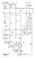
- FIG. 1 illustrated schematically embodiment.
- the exemplary embodiment shows a cryogenic gas condensing unit operating on the principle of the condensation process in which a hydrogen and a carbon monoxide product are produced from a dry and carbon dioxide-free feed gas, which consists predominantly of carbon monoxide and hydrogen and has small amounts of impurities such as methane and argon.
- the feed gas is introduced at a pressure of about 38 bar in the first, designed as a plate heat exchanger heat exchanger E1 and there cooled against process streams to be cooled to a temperature of about -160 ° C, before they via line 2 in the also as a plate heat exchanger executed heat exchanger E2 is performed.
- the feed gas is cooled to about -195 ° C and converted by partial condensation in a two-phase mixture, which is then introduced via line 3 in the Hochruckabscheider D1 and there separated into a hydrogen-rich gas fraction 4 and a carbon monoxide-rich hydrogen-containing liquid fraction 5 ,
- the hydrogen-rich gas fraction 4 is heated in the heat exchanger to about -170 ° C and fed via line 6 of the expansion turbine P, in which it is depressurized to a pressure of about 27 bar relaxed.
- the relaxed hydrogen-rich gas fraction 7 is heated in the heat exchanger E1 to ambient temperature and fed via line 8 of the pressure swing adsorber station DWA, where it is purified and processed into a hydrogen product 9.
- the resulting in the pressure swing adsorber DWA residual gas 10, which consists to a considerable extent of carbon monoxide is compressed in the compressor V and returned to the feed gas 1.
- the carbon monoxide-rich, hydrogen-containing liquid fraction 5 is depressurized via the throttle body a to a pressure which is greater than or equal to the Pressure of the relaxed hydrogen-rich gas fraction 7, and separated in the separator D2 in a second hydrogen-rich gas fraction 11 and a second carbon monoxide-rich hydrogen-containing liquid fraction 12.
- the second hydrogen-rich gas fraction 11 is then warmed in the heat exchanger E2 to about -170 ° C and combined via line 13 with the relaxed hydrogen-rich gas fraction 7.
- the hydrogen-rich gas fraction 13 can also be heated independently of the hydrogen-rich gas fraction 7 in the heat exchanger E1 and subsequently - for example in the pressure swing adsorber DWA - be merged with the hydrogen-rich gas fraction 8.
- the second carbon monoxide rich, hydrogen-containing liquid fraction 12 is cooled by the throttle body b to a pressure which is lower than the pressure of the expanded hydrogen-rich gas fraction 7, and introduced into the separator D3.
- the third carbon monoxide-rich, hydrogen-containing liquid fraction 14 separated in the separator D3 is further expanded via the throttle member c to a pressure of about 2 bar and passed into the separator D4, where it is separated into a fourth hydrogen-rich gas fraction 15 and a sufficiently hydrogen-free carbon monoxide-rich liquid fraction 16 becomes.
- a portion 17 of the carbon monoxide-rich liquid fraction 16 is branched off, expanded via the throttle body d and combined with the hydrogen-rich gas stream 18, which is formed from the third 19 and the fourth hydrogen-rich gas fraction 15 obtained in the separator D3.
- the total amount of the two hydrogen-rich gas fractions 15 and 19 is sufficient to reduce the carbon monoxide partial pressure in the substance mixture 20 so far that it evaporates at low temperature in the heat exchanger E2 and generates the peak cooling required for the process to reach the desired temperature in the separator D1, which is decisive for the purity of the H 2 fraction.
- the mixture 20 is vaporized and warmed in the two heat exchangers E1 and E2 and also recycled as recycle gas 29 via line 10 and the compressor V in the feed gas 1.
- the first partial stream 22 is passed directly as reflux to the top of the rectification column R, while the second partial stream 23 is first evaporated in the heat exchanger E2 and then fed as an intermediate feed of the rectification column R.
- the energy for generating the required rectification vapor is withdrawn from the condensing feed gas via the reboiler 24 integrated in the heat exchanger E2.
- a carbon monoxide stream 25 having a product purity is withdrawn, heated in the heat exchanger E1 and fed as carbon monoxide product 26 to the plant boundary.
- the higher-boiling impurities which collect in the bottom of the rectification column R are withdrawn with the stream 27.
- the stream 27 is used after evaporation and heating in the heat exchanger E1 as fuel gas 28.
Landscapes
- Engineering & Computer Science (AREA)
- Physics & Mathematics (AREA)
- Mechanical Engineering (AREA)
- Thermal Sciences (AREA)
- General Engineering & Computer Science (AREA)
- Chemical & Material Sciences (AREA)
- Organic Chemistry (AREA)
- Combustion & Propulsion (AREA)
- Inorganic Chemistry (AREA)
- Separation By Low-Temperature Treatments (AREA)
- Hydrogen, Water And Hydrids (AREA)
Applications Claiming Priority (1)
| Application Number | Priority Date | Filing Date | Title |
|---|---|---|---|
| DE102008059716A DE102008059716A1 (de) | 2008-11-29 | 2008-11-29 | Prozess zur Minimierung von Rückführgas in einem Kondensationsprozess |
Publications (2)
| Publication Number | Publication Date |
|---|---|
| EP2192365A2 true EP2192365A2 (fr) | 2010-06-02 |
| EP2192365A3 EP2192365A3 (fr) | 2012-09-26 |
Family
ID=42027916
Family Applications (1)
| Application Number | Title | Priority Date | Filing Date |
|---|---|---|---|
| EP09013917A Withdrawn EP2192365A3 (fr) | 2008-11-29 | 2009-11-05 | Procédé de minimisation de gaz de recyclage dans un procédé de condensation partielle |
Country Status (4)
| Country | Link |
|---|---|
| EP (1) | EP2192365A3 (fr) |
| CN (1) | CN101832697A (fr) |
| DE (1) | DE102008059716A1 (fr) |
| RU (1) | RU2009144105A (fr) |
Cited By (4)
| Publication number | Priority date | Publication date | Assignee | Title |
|---|---|---|---|---|
| WO2014019697A3 (fr) * | 2012-08-02 | 2015-06-18 | Linde Aktiengesellschaft | Procédé de séparation cryogénique du méthane depuis un gaz de synthèse, en particulier un gaz oxo |
| WO2017144151A1 (fr) * | 2016-02-25 | 2017-08-31 | Linde Aktiengesellschaft | Procédé et dispositif de décomposition cryogénique d'un gaz de synthèse |
| WO2021162759A1 (fr) * | 2020-02-14 | 2021-08-19 | Praxair Technology, Inc. | Procédé pour un fonctionnement amélioré de colonne de distillation de monoxyde de carbone à condensation partielle |
| RU2795927C2 (ru) * | 2018-11-16 | 2023-05-15 | Текнип Франс | Способ обработки питающего газового потока и установка для его осуществления |
Families Citing this family (2)
| Publication number | Priority date | Publication date | Assignee | Title |
|---|---|---|---|---|
| CN106403500B (zh) * | 2016-11-08 | 2019-03-05 | 苏州金宏气体股份有限公司 | 基于膨胀制冷提纯一氧化碳的方法及用于该方法的装置 |
| DE102020117937A1 (de) * | 2020-07-07 | 2022-01-13 | Linde Gmbh | Verfahren und eine Anlage zur Auftrennung eines Einsatzstroms |
Family Cites Families (5)
| Publication number | Priority date | Publication date | Assignee | Title |
|---|---|---|---|---|
| GB1304568A (fr) * | 1970-08-13 | 1973-01-24 | ||
| US4217759A (en) * | 1979-03-28 | 1980-08-19 | Union Carbide Corporation | Cryogenic process for separating synthesis gas |
| DE3215829A1 (de) * | 1982-04-28 | 1983-11-03 | Linde Ag, 6200 Wiesbaden | Verfahren zur gewinnung von kohlenmonoxid |
| DE4325513A1 (de) * | 1993-06-17 | 1994-12-22 | Linde Ag | Verfahren zur Gewinnung eines hochreinen Kohlenmonoxid-Produktstromes und eines Wasserstoff-Produktstromes |
| FR2780391B1 (fr) * | 1998-06-26 | 2000-10-20 | Air Liquide | Procede de production de monoxyde de carbone |
-
2008
- 2008-11-29 DE DE102008059716A patent/DE102008059716A1/de not_active Withdrawn
-
2009
- 2009-11-05 EP EP09013917A patent/EP2192365A3/fr not_active Withdrawn
- 2009-11-26 CN CN200910224931A patent/CN101832697A/zh active Pending
- 2009-11-27 RU RU2009144105/06A patent/RU2009144105A/ru not_active Application Discontinuation
Non-Patent Citations (1)
| Title |
|---|
| W. BALS; R. FABIAN, LINDE BERICHTE AUS WISSENSCHAFT UND TECHNIK, no. 47, 1980, pages 22 - 25 |
Cited By (5)
| Publication number | Priority date | Publication date | Assignee | Title |
|---|---|---|---|---|
| WO2014019697A3 (fr) * | 2012-08-02 | 2015-06-18 | Linde Aktiengesellschaft | Procédé de séparation cryogénique du méthane depuis un gaz de synthèse, en particulier un gaz oxo |
| WO2017144151A1 (fr) * | 2016-02-25 | 2017-08-31 | Linde Aktiengesellschaft | Procédé et dispositif de décomposition cryogénique d'un gaz de synthèse |
| RU2795927C2 (ru) * | 2018-11-16 | 2023-05-15 | Текнип Франс | Способ обработки питающего газового потока и установка для его осуществления |
| WO2021162759A1 (fr) * | 2020-02-14 | 2021-08-19 | Praxair Technology, Inc. | Procédé pour un fonctionnement amélioré de colonne de distillation de monoxyde de carbone à condensation partielle |
| CN114981602A (zh) * | 2020-02-14 | 2022-08-30 | 普莱克斯技术有限公司 | 用于改善的部分冷凝一氧化碳冷箱操作的方法 |
Also Published As
| Publication number | Publication date |
|---|---|
| CN101832697A (zh) | 2010-09-15 |
| EP2192365A3 (fr) | 2012-09-26 |
| RU2009144105A (ru) | 2011-06-10 |
| DE102008059716A1 (de) | 2010-06-02 |
Similar Documents
| Publication | Publication Date | Title |
|---|---|---|
| DE69305246T3 (de) | Verfahren und Apparat zur Herstelling von gasförmigem Sauerstoff unter Druck | |
| DE69504735T2 (de) | Verfahren und Anlage zur Herstellung von Kohlenmonoxyd | |
| DE69504398T2 (de) | Verfahren und Vorrichtung für die Trennung einer Gasmischung | |
| DE102013007208A1 (de) | Verfahren zum Gewinnen einer Methan-reichen Flüssigfraktion | |
| DE102010044646A1 (de) | Verfahren zum Abtrennen von Stickstoff und Wasserstoff aus Erdgas | |
| EP1067345A1 (fr) | Procédé et dispositif pour la séparation cryogénique des constituants de l'air | |
| DE69004994T2 (de) | Lufttrennung. | |
| EP1729077B1 (fr) | Procédé et dispositif pour la récupération de produits d'un gaz de synthèse | |
| DE102009048456A1 (de) | Verfahren und Vorrichtung zur Tieftemperaturzerlegung von Luft | |
| DE102008007925A1 (de) | Verfahren zur Helium-Gewinnung | |
| EP1724542B1 (fr) | Procédé et dispositif pour la récupération de produits d'un gaz de synthèse | |
| DE102008059716A1 (de) | Prozess zur Minimierung von Rückführgas in einem Kondensationsprozess | |
| DE60018083T2 (de) | Verfahren und Vorrichtung zur Abtrennung von Kohlenmonoxid und Wasserstoff aus einem Gasgemisch | |
| WO2008064762A2 (fr) | Procédé et dispositif d'obtention de produits provenant d'un gaz de synthèse | |
| DE19541339B4 (de) | Verfahren zum Gewinnen von Kohlenmonoxid | |
| EP1006326B1 (fr) | Procédé et dispositif pour la production d'oxygène sous pression et de krypton/xenon par séparation cryogénique d'air | |
| WO2010060533A1 (fr) | Extraction d'hélium | |
| EP2669613A1 (fr) | Procédé et dispositif destinés à la liquéfaction d'azote | |
| WO2006092266A1 (fr) | Procede d'extraction simultanee d'une fraction pure d'helium et d'une fraction pure d'azote | |
| DE60012382T2 (de) | Luftzerlegung | |
| DE102016002225A1 (de) | Verfahren und Vorrichtung zur kryogenen Synthesegaszerlegung | |
| DE10106484A1 (de) | Verfahren zum gleichzeitigen Gewinnen einer Helium- und einer Stickstoff-Reinfraktion | |
| DE102012020470A1 (de) | Verfahren und Vorrichtung zur Abtrennung von Methan aus einem Synthesegas | |
| DE102007062213A1 (de) | Verfahren und Vorrichtung zur Gewinnung von Oxogas | |
| DE102011113262A1 (de) | Verfahren und Vorrichtung zur Gewinnung von Drucksauerstoff durch Tieftemperaturzerlegung von Luft |
Legal Events
| Date | Code | Title | Description |
|---|---|---|---|
| PUAI | Public reference made under article 153(3) epc to a published international application that has entered the european phase |
Free format text: ORIGINAL CODE: 0009012 |
|
| AK | Designated contracting states |
Kind code of ref document: A2 Designated state(s): AT BE BG CH CY CZ DE DK EE ES FI FR GB GR HR HU IE IS IT LI LT LU LV MC MK MT NL NO PL PT RO SE SI SK SM TR |
|
| AX | Request for extension of the european patent |
Extension state: AL BA RS |
|
| PUAL | Search report despatched |
Free format text: ORIGINAL CODE: 0009013 |
|
| AK | Designated contracting states |
Kind code of ref document: A3 Designated state(s): AT BE BG CH CY CZ DE DK EE ES FI FR GB GR HR HU IE IS IT LI LT LU LV MC MK MT NL NO PL PT RO SE SI SK SM TR |
|
| AX | Request for extension of the european patent |
Extension state: AL BA RS |
|
| RIC1 | Information provided on ipc code assigned before grant |
Ipc: F25J 3/02 20060101AFI20120820BHEP Ipc: C01B 3/50 20060101ALI20120820BHEP |
|
| STAA | Information on the status of an ep patent application or granted ep patent |
Free format text: STATUS: THE APPLICATION IS DEEMED TO BE WITHDRAWN |
|
| 18D | Application deemed to be withdrawn |
Effective date: 20130327 |