EP2192371A2 - Accumulateur thermique de liquide doté d'une formation de couches de températures horizontale - Google Patents
Accumulateur thermique de liquide doté d'une formation de couches de températures horizontale Download PDFInfo
- Publication number
- EP2192371A2 EP2192371A2 EP09175095A EP09175095A EP2192371A2 EP 2192371 A2 EP2192371 A2 EP 2192371A2 EP 09175095 A EP09175095 A EP 09175095A EP 09175095 A EP09175095 A EP 09175095A EP 2192371 A2 EP2192371 A2 EP 2192371A2
- Authority
- EP
- European Patent Office
- Prior art keywords
- storage
- storage vessel
- liquid
- vessel
- vessels
- Prior art date
- Legal status (The legal status is an assumption and is not a legal conclusion. Google has not performed a legal analysis and makes no representation as to the accuracy of the status listed.)
- Withdrawn
Links
Images



Classifications
-
- F—MECHANICAL ENGINEERING; LIGHTING; HEATING; WEAPONS; BLASTING
- F28—HEAT EXCHANGE IN GENERAL
- F28D—HEAT-EXCHANGE APPARATUS, NOT PROVIDED FOR IN ANOTHER SUBCLASS, IN WHICH THE HEAT-EXCHANGE MEDIA DO NOT COME INTO DIRECT CONTACT
- F28D20/00—Heat storage plants or apparatus in general; Regenerative heat-exchange apparatus not covered by groups F28D17/00 or F28D19/00
- F28D20/0034—Heat storage plants or apparatus in general; Regenerative heat-exchange apparatus not covered by groups F28D17/00 or F28D19/00 using liquid heat storage material
- F28D20/0039—Heat storage plants or apparatus in general; Regenerative heat-exchange apparatus not covered by groups F28D17/00 or F28D19/00 using liquid heat storage material with stratification of the heat storage material
-
- F—MECHANICAL ENGINEERING; LIGHTING; HEATING; WEAPONS; BLASTING
- F28—HEAT EXCHANGE IN GENERAL
- F28D—HEAT-EXCHANGE APPARATUS, NOT PROVIDED FOR IN ANOTHER SUBCLASS, IN WHICH THE HEAT-EXCHANGE MEDIA DO NOT COME INTO DIRECT CONTACT
- F28D20/00—Heat storage plants or apparatus in general; Regenerative heat-exchange apparatus not covered by groups F28D17/00 or F28D19/00
- F28D2020/0065—Details, e.g. particular heat storage tanks, auxiliary members within tanks
- F28D2020/0082—Multiple tanks arrangements, e.g. adjacent tanks, tank in tank
-
- Y—GENERAL TAGGING OF NEW TECHNOLOGICAL DEVELOPMENTS; GENERAL TAGGING OF CROSS-SECTIONAL TECHNOLOGIES SPANNING OVER SEVERAL SECTIONS OF THE IPC; TECHNICAL SUBJECTS COVERED BY FORMER USPC CROSS-REFERENCE ART COLLECTIONS [XRACs] AND DIGESTS
- Y02—TECHNOLOGIES OR APPLICATIONS FOR MITIGATION OR ADAPTATION AGAINST CLIMATE CHANGE
- Y02E—REDUCTION OF GREENHOUSE GAS [GHG] EMISSIONS, RELATED TO ENERGY GENERATION, TRANSMISSION OR DISTRIBUTION
- Y02E60/00—Enabling technologies; Technologies with a potential or indirect contribution to GHG emissions mitigation
- Y02E60/14—Thermal energy storage
Definitions
- the present invention relates to a liquid heat storage.
- a liquid heat storage is often used in the prior art. In this case it is attempted to build up a thermal coating in such a heat accumulator, ie warm or hot storage liquid at the top, colder or cold storage liquid at the bottom. As storage liquid water is usually used.
- such a liquid heat storage consists of a single closed storage vessel which is filled with the storage liquid.
- the liquid heat storage device has at least one heating device, by means of which the storage liquid located in the storage vessel can be heated.
- Such liquid heat storage exist among other things as so-called daily storage, which can hold the stored heat in them a few days, for example, two to eight days.
- Daily storage usually has a volume in the single-digit cubic meter range or slightly lower.
- seasonal storage which are heated in the summer and release the heat stored in them over the winter.
- Seasonal storage must be sized much larger than daily storage. They usually have a storage volume of 50 m 3 or more.
- Jenni houses As seasonal storage, the so-called Jenni houses are known.
- a storage vessel In a Jenni house, a storage vessel is set up, which has a floor area of about 8 to 20 m 2 .
- the storage vessel is about 8 to 12 m high.
- Such a memory is practically feasible only in a new building, in which the house to be built is built so to speak around the storage vessel around.
- the liquid heat storage is designed as a daily storage or seasonal storage, there are other disadvantages in the prior art.
- the "heating point" ie the point at which the heating device is located or the heated storage liquid is supplied to the storage vessel, must be arranged in the bottom area of the storage vessel. Otherwise, the lower area of the storage vessel could not be heated up. In this case, it is usually not possible to remove heat already a short time after the start of the heating process to heat process water. As a rule, it is necessary to wait until the entire vessel contents of the storage vessel have warmed up. This is particularly problematic in the winter months.
- a liquid heat accumulator which has a plurality of closed storage vessels.
- the storage vessels are filled with a storage liquid and connected to each other at the bottom so as to form a sequence.
- the first storage vessel has a circulation supply point, at least one other of the storage vessels a circulation withdrawal point.
- the circulation removal point of the other storage vessel is at least temporarily connected to the circulation supply point of the first storage vessel via a line.
- a pump is arranged, by means of which the storage liquid from the other storage vessel is pumpable into the first storage vessel.
- a heating device is further arranged, by means of which the storage liquid pumped from the other storage vessel into the first storage vessel can be heated.
- Internal guide tubes are arranged within the individual storage vessels, by means of which the storage liquid supplied to the respective storage vessel is forcibly directed into the ceiling region of the respective storage vessel.
- a liquid heat storage which has a plurality of closed storage vessels, which are filled with a storage liquid.
- the liquid heat storage device has a heating device, by means of which the storage liquid located in a central one of the storage vessels can be heated.
- the storage vessels are communicatively connected with each other.
- a liquid heat storage which has a plurality of closed storage vessels, which are filled with a storage liquid.
- the storage vessels are not connected to each other.
- the storage vessels cooperate with each other in such a way that each storage vessel has an insulation in which a heating element is arranged which receives the heat radiated from the respective storage vessel and supplies it to the respective downstream storage vessel.
- a liquid heat storage which has a plurality of closed storage vessels.
- the storage vessels are filled with a storage liquid and connected together so that they form a sequence.
- At least the first storage vessel has a circulation supply point, at least one other of the storage vessels a circulation withdrawal point.
- the circulation removal point of the other storage vessel is connected to the circulation supply point of the first storage vessel via a line.
- the liquid heat storage on a heater.
- the object of the present invention is to provide a liquid heat storage, which is simple in construction, reliable and yet allows in a simple way, in particular a rapid hot water heating.
- the liquid heat store has a plurality of closed storage vessels.
- the storage vessels are filled with a storage fluid.
- the storage vessels are connected on the bottom side in such a way that they form a sequence.
- At least the first storage vessel has a circulation supply point, at least one other of the storage vessels a circulation withdrawal point.
- the circulation removal point of the other storage vessel is at least temporarily connected to the circulation supply point of the first storage vessel via a line.
- a pump is arranged, by means of which the storage liquid from the other storage vessel is pumpable into the first storage vessel.
- the liquid heat storage device has a heating device, by means of which the storage liquid pumped from the other storage vessel into the first storage vessel is heated.
- the other storage vessel and any storage vessels arranged in the sequence of storage vessels between the first and the other storage vessels are designed such that the storage liquid conveyed via the respective bottom-side connection into the respective storage vessel in the event that they are warmer than those already in the respective storage vessel Storage fluid is in the respective storage vessel rises up until it reaches the ceiling region of the respective storage vessel or encounters a layer of the storage liquid, which has the same temperature. Otherwise, the stored in the respective storage vessel storage liquid remains in the bottom region of the respective storage vessel.
- the heating power of a solar system or a combined heat and power plant is sufficient to heat the storage liquid flowing into the first storage vessel over the temperature that the storage liquid surrounding the circulation supply point of the first storage vessel has, the supplied (necessarily warmer) storage liquid in the first storage vessel increases upward until it either reaches the ceiling area of the first storage vessel or encounters a liquid layer of the same temperature. All colder layers are displaced downwards without destroying an existing thermal coating.
- the supplied storage liquid which is warm as required
- the temperature of the uppermost layer of the storage liquid in the first storage vessel is increased. Otherwise, the temperature of the uppermost layer will not increase, but the layer will not be displaced or destroyed.
- the heating power of the solar system or cogeneration plant is not sufficient to heat the flowing in the first storage vessel storage liquid over the temperature, which the In the first storage vessel located storage liquid in the vicinity of the circulation supply point of the first storage vessel, so decreases the supplied (cold as expected) storage liquid down until it either reaches the bottom of the first storage vessel or strikes a liquid layer of the same temperature.
- the coldest storage liquid of the first storage vessel is withdrawn from the first storage vessel, ie either the supplied storage liquid if this is too cold or the coldest layer of the storage liquid already in the first storage vessel.
- the storage liquid transferred from the first to the second storage vessel on the bottom side displaces all liquid layers there, which are colder than the storage liquid transferred from the first storage vessel to the second storage vessel. If the transferred storage liquid is too cold to displace the storage liquid in the second storage vessel, it is simply forwarded through the second storage vessel to the third storage vessel.
- An analogous process also takes place in the further storage vessels up to the storage vessel which has the circulation removal point which is just connected to the circulation supply point of the first storage vessel.
- the heating device is designed as a heat exchanger.
- heat exchanger refers to a device in which a warm liquid releases its temperature to a colder liquid or, conversely, the colder liquid is heated by the warmer liquid.
- the heating device can be arranged outside the storage vessels.
- the heating device may be designed as a solar system or as a combined heat and power plant.
- the storage liquid supplied to the first storage vessel is heated before being supplied to the first storage vessel.
- the heating device it is possible for the heating device to be arranged inside the first storage vessel. Also in this case, the storage liquid supplied to the first storage vessel may be heated before being supplied to the first storage vessel. In this case, therefore, the storage liquid is heated even before it enters the first storage vessel. Alternatively, however, it is possible for the storage liquid located in the vicinity of the circulation supply point of the first storage vessel to be heated by means of the heating device within the first storage vessel, so that the storage liquid flowing into the first storage vessel is heated after being supplied to the first storage vessel. This latter embodiment is preferred.
- the advantage of the last-mentioned embodiment is that the storage liquid in the first storage vessel can be heated by means of the heating device without having to heat the storage liquid in the other storage vessels.
- the circulation supply point In the case of the first storage vessel, it is preferable for the circulation supply point to be arranged approximately in the center of the first storage vessel when viewed in the vertical direction.
- the circulation removal point of the other storage vessel may be arranged as needed. In particular, it may be arranged in the ceiling region of the other storage vessel. This embodiment may be useful, in particular, if the other storage vessel is a storage vessel different from the last storage vessel of the sequence.
- the other storage vessel has a further circulation removal point which is at least temporarily connected via the pump or another pump to a circulation supply point of a storage vessel arranged downstream of the other storage vessel in the sequence of storage vessels.
- a connection of the storage vessel downstream of the other storage vessel can take place when the other storage vessel has reached its full operating temperature.
- the circulation supply point of the downstream storage vessel is preferably arranged in the ceiling region of the downstream storage vessel. This has the effect that the warm storage liquid supplied from the other storage vessel is stored in the ceiling region of the downstream storage vessel and the cold storage liquid located in the downstream storage vessel is withdrawn from its bottom area.
- the downstream storage vessel also has a circulation removal point in its ceiling area, which via the pump or another pump with a circulation supply point of a storage vessel upstream of the downstream storage vessel in the sequence of storage vessels, in particular the first or the other Storage vessel, at least temporarily connected.
- This configuration makes it possible to unload the downstream storage vessel in a simple manner, ie to remove the warm storage liquid stored there.
- the liquid heat accumulator has a one-piece outer shell, that the outer shell forms the outer wall of the second and the third storage vessel, that in the outer shell, a vertically extending partition wall is arranged, that the partition second and the third storage vessel from each other and that the first storage vessel is disposed within the second storage vessel.
- the partition is spaced from the bottom of the outer shell, so that the bottom-side connection of the second and the third storage vessel is formed with each other by the spacing.
- the bottom-side connection can be produced in a simple manner.
- the outer shell has a greater extent horizontally than vertically.
- the outer shell is easy to set up and stable, because it is horizontal and not standing. The stability results regardless of whether the outer shell is arranged above ground or below ground.
- the partition may be disposed within the outer shell as needed.
- the dividing wall is arranged off-center in the horizontal direction, so that the third storage vessel has a larger volume than the second storage vessel. It can consist of an insulating material, such as polyurethane foam.
- the outer shell is preferably surrounded by an insulating layer.
- the thickness of the insulating layer - can be selected as needed. As a rule, it will be at least 50 mm.
- the insulating layer may be formed as a bed, for example, as a bed of expanded clay spheres or the like. Often, however, the insulating layer will be formed as a dimensionally stable foaming.
- a protective layer is applied to the dimensionally stable foaming on the outside. The protective layer may in particular be sprayed on.
- the protective layer is preferably weather-resistant, tear and abrasion resistant and waterproof and water resistant.
- the outer shell in the region of the second storage vessel on its upper side an access opening, which in turn has an opening cross-section.
- the outer shell may have on its upper side a molded neck, which forms a manhole.
- the first storage vessel has, seen horizontally, a vessel cross section which is smaller than the opening cross section. This makes it possible to pre-assemble the first storage vessel and a majority of the casing and the heat exchanger and to arrange as a unit in the second storage vessel.
- the first storage vessel is separated from the second storage vessel by an intermediate casing.
- the intermediate shell may consist of an insulating material, such as polyurethane foam.
- the first storage vessel has a greater extent vertically than horizontally.
- the first storage vessel is thus preferably - in contrast to the outer shell - standing (or rather hanging) arranged.
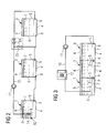
- FIG. 1 a liquid heat storage on a plurality of storage vessels 1, 2, 3.
- the minimum number of storage vessels 1, 2, 3 is two. Normally, three or four such storage vessels 1, 2, 3 are present. In individual cases, more storage vessels 1, 2, 3 may be present.
- the storage vessels 1, 2, 3 are closed, so they have not only a respective bottom 4 and respective side walls 5, but also a respective cover 6.
- the storage vessels 1, 2, 3 are filled with a storage liquid 7, which is in the situation To store heat.
- the storage liquid 7 is water.
- another liquid as the storage liquid 7, for example an oil or a liquid metal.
- the ceilings 6 of the storage vessels 1, 2, 3 can, as in FIG. 1 shown, be firmly mounted.
- the ceilings 6 may be formed as covers, which are arranged on the storage liquid 7.
- it may be polystyrene panels or tarpaulins. It is crucial that the storage vessels 1, 2, 3 are not open to the top, otherwise too large heat losses would occur.
- the design of the storage vessels 1, 2, 3 can be selected as needed. As a rule, they have (horizontally) a rectangular or a cylindrical cross-section.
- a rectangular cross-section has the advantage that it is usually easier to implement structurally.
- a circular cross-section results in the same circumference an optimized cross-sectional area. Seen in the vertical direction, the cross section is usually constant. However, this is not mandatory.
- the storage vessels 1, 2, 3 may be cylinders lying.
- the storage vessels 1, 2, 3 are connected to one another at the bottom, so that the storage liquid 7 can flow from each of the storage vessels 1, 2, 3 into the directly adjacent storage vessels 1, 2, 3 on the bottom side. On the basis of their bottom-side connection, the storage vessels 1, 2, 3 form a sequence.
- At least the first storage vessel 1 has a circulation supply point 8. At least one other of the storage vessels 1, 2, 3 - according to the embodiment of FIG. 1 the last storage vessel 3 - has a circulation removal point 9. The circulation removal point 9 of the other storage vessel 3 is at least temporarily connected to the circulation supply point 8 of the first storage vessel 1.
- FIG. 1 the circulation supply point 8 of the first storage vessel 1 is seen in the vertical direction approximately in the middle of the first storage vessel 1 is arranged.
- the circulation removal point 9 of the other storage vessel 3 is in the embodiment of the liquid heat storage according to FIG. 1 arranged in the bottom region of the other storage vessel 3. It could alternatively be arranged in the ceiling area or approximately in the center of the other storage vessel 3.
- the bottom regions of the storage vessels 1, 2, 3 are arranged in the sequence of the sequence, preferably at the same level or in descending order.
- the bottom area of the second storage vessel 2 is in this case at the same altitude as the bottom area of the first storage vessel 1 or below.
- the bottom portion of the third storage vessel 3 is at the level of the second storage vessel 2 or below, and so on.
- the circulation removal point 9 of the last storage vessel 3 is connected to the circulation supply point 8 of the first storage vessel 1 - usually via a line 10.
- a pump 11 is arranged, by means of which the storage liquid 7 is pumped through the conduit 10 therethrough.
- the liquid heat storage device has a heating device 12.
- the heating device 12 By means of the heating device 12, the storage liquid 7 can be heated, which flows from the last storage vessel 3 into the first storage vessel 1.
- the heater 12 may be formed as needed.
- the heating device 12 is designed as a heat exchanger, that is, the storage liquid 7 is heated by receiving the heat of another liquid. Examples of such heat exchangers are solar panels.
- the heater 12 is disposed outside the storage vessels 1, 2, 3. In this case, the line 10 flowing through the storage liquid 7 is heated, so even before feeding to the first storage vessel. 1
- the liquid heat accumulator according to the embodiment of FIG. 1 works as follows:
- the storage liquid 7 is withdrawn from the last storage vessel 3.
- the withdrawn storage liquid 7 is supplied to the heater 12.
- the storage liquid 7 is heated.
- the storage liquid 7 is supplied to the first storage vessel 1.
- the supplied storage liquid 7 When the temperature of the storage liquid 7 supplied to the first storage vessel 1 is greater than the temperature of the storage liquid 7 in the vicinity of the circulation supply point 8 of the first storage vessel 1, the supplied storage liquid 7 has a (albeit slightly) lower density than the storage liquid surrounding it 7 on. It therefore rises in the first storage vessel 1 upwards until it either encounters a heat layer with the same temperature or reaches the ceiling region of the first storage vessel 1. At the same time, all colder temperature layers of the storage liquid 7 within the first storage vessel 1 are displaced downwards. The lowest and therefore coldest layer of the storage liquid 7 is withdrawn from the first storage vessel 1 and fed to the second storage vessel 2.
- the supplied storage liquid 7 When the temperature of the storage liquid 7 supplied to the first storage vessel 1 is smaller than the temperature of the storage liquid 7 in the vicinity of the circulation supply 8 of the first storage vessel 1, the supplied storage liquid 7 has a density (even slightly) greater than that surrounding it Storage fluid 7 on.
- the supplied storage liquid 7 therefore sinks within the first storage vessel 1 down until it either encounters a layer of the same temperature or reaches the bottom area of the first storage vessel 1. In the event that the supplied storage liquid 7 encounters a layer of the same temperature during descent, it displaces all the colder layers of the storage liquid 7 within the first storage vessel 1 down.
- the storage liquid 7 located in the bottom area (and thus the coldest storage liquid 7) is withdrawn from the first storage vessel 1 and fed to the second storage vessel 2.
- the storage liquid 7 supplied to the first storage vessel 1 is always stored "correctly" within the first storage vessel 1 and, furthermore, the coldest storage liquid 7 is always withdrawn from the first storage vessel 1 and supplied to the second storage vessel 2.
- the heating device 12 is disposed within the first storage vessel 1, in the region of the circulation supply point 8 of the first storage vessel 1.
- the storage liquid 7 which flows into the first storage vessel 1, heated only when they are in a line section 13 which extends within the first storage vessel 1, or when it has already leaked out of the conduit 10.
- This embodiment has the advantage that - in the functional sense - a decoupling of the first storage vessel 1 from the other storage vessels 2, 3 is possible. Because the liquid heat storage of FIG. 2 is - of course - analogous to the liquid heat storage of FIG. 1 operable with the pump 11 switched on. In this case, the operation of the liquid heat storage of FIG. 2 as above in connection with FIG. 1 has already been explained.
- the first storage vessel 1 is arranged within the second storage vessel 2, it is further preferred for the first storage vessel 1 to have a smaller cross-section (and possibly also a smaller overall height) than the second storage vessel 2. This makes it possible that the side walls 5 of the first storage vessel 1 are spaced from the side walls 5 of the second storage vessel 2 and possibly also the bottom 4 and / or the ceiling 6 of the first storage vessel 1 from the bottom 4 and the ceiling 6 of the second storage vessel 2 are spaced. As a result, heat losses can be further reduced.
- the storage vessels 1, 2, 3 are arranged adjacent to one another or interlaced, it is not absolutely necessary for the side walls 5 of the storage vessels 1, 2, 3 to be different from each other.
- the separation of the storage vessels 1, 2 from each other can be realized by a common partition that leaves a small gap on the bottom side.
- the storage vessels 1, 2, 3 can - theoretically - have the same effective vessel volumes among each other.
- the first storage vessel 1 corresponding to the representation of FIG. 5
- the term "considerably smaller” here denotes an order of magnitude, ie the factor 10.
- the vessel volume of the first storage vessel 1 can amount to a maximum of 2 m 3 .
- the vessel volumes of the other storage vessels 2, 3 are preferably individually at least 20 m 3 and / or together at least 50 m 3 .
- first storage vessel 1 has a vessel volume of about 1 m 3 to 1.5 m 3 and the second and the third storage vessel 2, 3 are approximately equal to each other and about each 40 m 3 to 50 m 3 have.
- first storage vessel 1 has a considerably smaller vessel volume than the other storage vessels 2, 3 facilitates, in particular, the arrangement of the first storage vessel 1 within the second storage vessel 2.
- this embodiment takes into account the fact that the storage liquid in the first storage vessel 1 7 is usually used for heating domestic water. For heating domestic water, although only a relatively small amount of storage liquid 7 is required. The required amount of storage fluid 7 must be relatively warm. Above all, it should be available very quickly after the start of the warm-up process.
- the storage liquid 7 located in the second and subsequent storage vessels 2, 3, however, is generally used for heating purposes. For heating (especially in the course of the entire winter) considerably larger quantities of storage liquid 7 are needed, the heating of which can also extend over a longer period of time.
- the storage vessels 1, 2, 3 can be arranged at a distance from one another.
- the storage vessels 1, 2, 3 preferably have insulating layers, by means of which they are insulated from their surroundings. Particularly important is the isolation of the first and the second storage vessel 1, 2.
- the storage vessels 1, 2, 3 are arranged next to each other or nested one inside the other.
- the storage vessels 1, 2, 3 - optionally in addition to isolation from their environment - be thermally insulated from each other.
- the extent to which the storage vessels 1, 2, 3 are isolated may vary from storage vessel 1, 2, 3 to storage vessel 1, 2, 3.
- the corresponding insulation of the first storage vessel 1 should be strongest, the second storage vessel 2 on the second strongest, etc ..
- the storage vessels 1, 2, 3 into each other it may be sufficient to isolate only the outermost storage vessel 2 and 3 respectively. Again, however, an isolation of the storage vessels 1, 2, 3 against each other is possible.
- the storage liquid 7 located in the first storage vessel 1 should be able to be heated up quickly. Often, it is even sufficient to be able to heat only the storage liquid 7 located in the upper part of the first storage vessel 1 (for example, the upper 10 to 25%) quickly. For this reason, according to the representation of FIG. 6 preferably provided that the circulation supply point 8 of the first storage vessel 1 is surrounded by a laminating tube 14.
- the laminating tube 14 may be used in any of the embodiments according to FIGS. 1 and 2 (and of course the FIGS. 3 to 5 ) to be available. In the FIGS. 1 and 2 is the stratification tube 14 shown in dashed lines.
- the laminating tube 14 has a lower end 15 and an upper end 16.
- the lower end 15 of the stratification tube 14 is in the height direction of the first storage vessel 1 seen from the bottom 4 of the first storage vessel 1 spaced.
- the distance is preferably determined such that a maximum of approximately 10 to 25% of the total storage liquid 7 located in the first storage vessel 1 is located below the lower end 15.
- the upper end 16 of the stratification tube 14 is spaced from the ceiling 6 of the first storage vessel 1.
- the distance is preferably selected such that a maximum of approximately 10 to 25% of the total volume of the storage liquid 7 located in the first storage vessel 1 is located above the upper end 16.
- the stated percentages may be different for the upper end 16 than for the lower end 15. However, they can be the same.
- the line 10 ends in the bottom region of the first storage vessel 1.
- liquid heat storage according to FIG. 7 is also a plurality of closed storage vessels 1, 2, 3, present. At a minimum, the storage vessels 1 and 2 must be present.
- the storage vessel 3 is only optional. It may be omitted if necessary.
- the storage vessels 1, 2, 3 are filled with the storage liquid 7 and the bottom side connected to each other so that they form a sequence. Furthermore, in the embodiment of FIG. 7 the bottom portions of the storage vessels 1, 2, 3 arranged in the sequence of sequence level or descending.
- the circulation supply point 8 of the first storage vessel 1 is according to the embodiment FIG. 7 Seen in the height direction approximately centrally of the first storage vessel 1 is arranged.
- the other storage vessel, which has the circulation removal point 9, is in the embodiment according to FIG. 7 not the last storage vessel 3, but the second storage vessel 2.
- the circulation removal point 9 is arranged at the second storage vessel 2 in the ceiling area. The connection of the circulation removal point 9 of the second storage vessel 2 with the circulation supply point 8 of the first storage vessel 1 via the pump 11th
- the heating device 12 in the embodiment of the liquid heat storage of FIG. 7 designed as a heat exchanger, which is arranged in the first storage vessel 1. Furthermore, in the embodiment according to FIG. 7 the laminating tube 14 is present. In the stratification tube 14, both the heat exchanger 12 and the circuit feed 8 are arranged.
- the liquid heat storage of FIG. 7 is operated as follows:
- the heat exchanger 12 is supplied via a conduit system 10 'warm liquid.
- the pump 11 is actuated, so that the storage liquid 7 is pumped from the ceiling region of the second storage vessel 2 into the stratification tube 14.
- Analogous to the above in connection with the FIGS. 1 and 2 described effect increases the supplied storage liquid 7 up when it is warm enough or is heated sufficiently. Otherwise, it emerges from the stratification tube 14 at the lower end 15 of the stratification tube 14.
- the coldest storage liquid 7 located in the first storage vessel 1 is always transferred into the second storage vessel 2 via the bottom connection of the first and second storage vessels 1, 2.
- FIG. 7 has the advantage that the introduced into the laminating tube 14 storage liquid 7 is not as cold as in the embodiment of FIGS. 1 and 2 , Thereby, the storage liquid 7 can be heated to a higher temperature level, so that even faster and more effective than in the embodiment of FIGS. 1 and 2 a small layer for heating domestic water is formed. Also, for example, even without operating the heat exchanger 12, warm storage liquid 7 can be pumped from the second storage vessel 2 into the first storage vessel 1 if the storage liquid 7 in the first storage vessel 1 is cold and the storage liquid 7 in the second storage vessel 2 is warm.
- the liquid heat accumulator according to the embodiment of FIG. 7 can be formed in various ways.
- a further heat exchanger 12 'in the second storage vessel 2 is preferably arranged in the lower part of the second storage vessel 2.
- the further heat exchanger 12 ' can be arranged in particular on the outside of the vessel wall 5 of the first storage vessel 1.
- the correspondingly modified liquid heat storage device is operated as follows:
- the warm liquid of the line system 10 ' is supplied to the heat exchanger 12 by means of a pump, not shown, as long as the liquid returned from the heat exchanger 12 is colder than the liquid supplied to the heat exchanger 12. Because in this case, heat is released to the storage liquid 7.
- the pump 11 is also actuated, so that it pumps the storage liquid 7 from the ceiling area of the second storage vessel 2 into the stratification tube 14.
- the warm liquid is directed to the further heat exchanger 12 'by means of the valve device 12.
- the pump 11 is switched off.
- the second storage vessel 2 has a further circulation removal point 9 which, at least temporarily, via a pump with a circulation supply point 8 of a storage vessel 3 arranged downstream of the second storage vessel 2 connected is.
- the further circulation removal point 9 of the second storage vessel 2 it is possible for the further circulation removal point 9 of the second storage vessel 2 to be a circulation withdrawal point that is different from the first-mentioned circulation removal point 9.
- a separate pump is used.
- the pump 11 is associated with a valve device 11 ', by means of which it is switchable, whether the pumped from the pump 11 storage liquid 7 is supplied to the first storage vessel 1 or the third storage vessel 3.
- the activation of the valve device 11 takes place when the storage liquid 7 located in the second storage vessel 2 has reached its setpoint temperature. This may alternatively be the same setpoint temperature as in the first storage vessel 1 or another setpoint temperature.
- the third storage vessel 3 in the embodiment of the liquid heat storage according to FIG. 7 is used as "buffer memory". For this reason, it is preferred that the circulation supply point 8 of the downstream storage vessel 3 is arranged in the ceiling region of the downstream storage vessel 3. Because this warm storage fluid 7 can be cached almost lossless in the third storage vessel.
- the downstream storage vessel 3 in its ceiling area also a circulation take-off point 9, the at least temporarily via a further pump 11 "with a circulation supply 8 of the downstream storage vessel 3 in the sequence of storage vessels 1, 2, 3 upstream storage vessel 1, 2
- the upstream storage vessel 2 may be the other storage vessel 2, that is, the second storage vessel 2, according to the exemplary embodiment, but is preferably the first storage vessel 1.
- the liquid heat storage device has a first use removal point 17 and a first use return point 18.
- 1 memory liquid 7 can be removed from the ceiling region of the first storage vessel 1 via the first Nutz-withdrawal point. About the first pay-return point 18, the removed storage liquid 7 is the first storage vessel 1 again fed.
- the storage liquid 7 removed via the first use removal point 17 can be supplied, for example, to a process water treatment device 19. In the process water treatment device 19 process water is treated, that is heated.
- the liquid heat storage usually also has a second useful removal point 20.
- 2 memory liquid 7 can be removed from the ceiling area of the second storage vessel 2 via the second Nutz-withdrawal point 20.
- the storage liquid 7 removed via the second useful extraction point 20 is likewise fed to the first storage vessel 1.
- the first pay-return point 18 can be used or a separate second pay-return point 21, different from the first pay-return point 18, can be present.
- the storage liquid 7 removed via the second useful removal point 20 can be supplied, for example, to a heating water treatment device 22 in order to heat heating water.
- the first pay-return point 18 is arranged below the circulation supply point 8 of the first storage vessel 1.
- the second pay-return point 21 is arranged below the circulation supply point 8 of the first storage vessel 1. This embodiment is preferred regardless of the presence or absence of the laminating tube 14. It is not mandatory.
- the first pay-return point 18 is arranged within the stratification tube 14.
- the second pay-return point 21 is disposed within the stratification tube 14. This embodiment is preferred, but not mandatory.
- FIG. 7 is in the first storage vessel 1 - more precisely: at least in the upper part of the first storage vessel 1, usually over a substantial part of the height of the first storage vessel 1 - a heat exchanger 19 'arranged.
- the heat exchanger 19 ' may be wound on the outside of the laminating tube 14.
- the heat exchanger 19 ' is cold service water can be fed. It passes through the heat exchanger 19 'and is the heat exchanger 19' as a hot service water removed. If necessary, the heat exchanger 19, a water heater 19 "downstream.
- FIG. 7 is further arranged in a first storage vessel 1 downstream storage vessel 2, in particular in the second storage vessel 2, a heat exchanger 22 '.
- the heat exchanger 22 ' can be supplied with cold water from a heating circuit 22 ", which is heated up in the heat exchanger 22' and returned to the heating circuit 22".
- the heat exchanger 22 ' is disposed within the storage vessel 2, in which it is arranged, in its upper part.
- it may be wound on the outside of the first storage vessel 1.
- downstream storage vessels 3 (in a design with a total of three storage vessels 1, 2, 3, the third storage vessel 3) release their heat over the course of time and can not be reheated for the time being.
- this case can occur in the winter months, especially in the second half of the winter.
- the design of the liquid heat storage of FIG. 7 has already been explained how such a decoupling can be done.
- the liquid heat accumulator has a switching device 23.
- the circulation removal point 9 of a different than the last storage vessel 3 with the line 10 is connected, as shown in the FIGS. 1 to 3 the second storage vessel 2.
- the storage vessels 3 (here only the third storage vessel 3) arranged downstream of the other (here the second) storage vessel 2 in the sequence of storage vessels 1, 2, 3 are separable from the line 10.
- the switching device 23 consists of two valves 24, which can be operated separately.
- the actuation can alternatively be done manually or automatically.
- the switching device 23 may be formed, for example, as a three-way valve. Also in this case, alternatively, a manual operation or an automatic operation is possible.
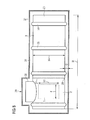
- FIGS. 8 to 10 a preferred mechanical design embodiment of the liquid heat accumulator according to the invention explained in more detail.
- the liquid heat accumulator has an outer shell 25.
- the outer shell 25 is integrally formed. It forms the outer wall of the second and the third storage vessel 2, 3.
- the outer shell 25 may for example consist of a plastic, in particular of a glass fiber reinforced plastic (GRP).
- the outer shell 25 has ribs 26 on its outer side. However, this is not mandatory.
- a partition wall 27 is arranged in the outer shell 25, .
- the partition wall 27 extends vertically. It separates the second storage vessel 2 and the third storage vessel 3 from each other.
- the partition wall 27 may consist of an insulating material, for example of a polyurethane foam.
- the partition wall 27 is slightly spaced from the bottom of the outer shell 25. This leaves between the partition wall 27 and the bottom of the outer shell 25, a gap 28.
- the gap 28 forms the bottom-side connection of the second and the third storage vessel 2, 3 with each other.
- the second and the third storage vessel 2, 3 are arranged side by side.
- the first storage vessel 1, however, is disposed within the second storage vessel 2.
- the liquid heat accumulator can be prefabricated and placed at its later site as a unit.
- the outer shell 25 has a greater horizontal extent than vertically.
- the outer shell 25 in the horizontal direction a length 1A of 8 to 15 m and in the vertical direction a height hA of 2 m to 4 m ("lying arrangement").
- the cross-section of the outer shell 25 can in principle be arbitrary. Preferred is a rectangular, hexagonal, octagonal or - particularly preferred - circular cross-section.
- the enclosed by the outer shell 26 volume is usually between 20 m 3 and 250 m 3 , for example, at 30 m 3 to 100 m 3 . Particularly preferred is a volume range of 40 m 3 to 60 m 3 .
- the arrangement of the partition 27 can be selected as needed.
- the dividing wall 27 can be arranged centrally in the horizontal direction, so that the partial volumes on both sides of the dividing wall 27 are the same size. Often, however, the dividing wall 27 is arranged eccentrically in the horizontal direction.
- the arrangement in this case is generally such that the third storage vessel 3 has a larger volume than the second storage vessel 2.
- the proportion of the third storage vessel 3 in the total volume enclosed by the outer shell 25 is usually 60 to 85%. The proportion usually increases with the total enclosed by the outer shell 25 volume.
- a division of 60:40 may be expedient (ie 36 m 3 for the third storage vessel 3, 24 m 3 for the first and the second storage vessel 1, 2).
- a division of, for example, 70:30 may be expedient (70 m 3 for the third storage vessel 3, 30 m 3 for the first and the second storage vessel 1, 2).
- a division of 76:24 can be selected (ie 114 m 3 for the third storage vessel 3, 36 m 3 for the first and the second storage vessel 1, 2).
- the outer shell 25 has an access opening 29 on its upper side in most cases.
- a nozzle 30 may be formed, which in turn contains the access opening 29.
- the access opening 29 has a cross section, hereinafter referred to as opening cross section.
- the opening cross-section is usually selected such that a person has access to the interior of the outer shell 25 via the access opening 29.
- the access opening 29 is therefore commonly referred to as a manhole. Due to the access opening 29, it is possible, for example, for a person to cover the outer shell 25 inspect their inside. Furthermore, it is possible, as part of the production of the liquid heat storage, to enter the volume enclosed by the outer shell 25 and, for example, to introduce the mentioned partition 27.
- the first storage vessel 1 viewed horizontally, also has a cross-section.
- This cross-section is referred to below as the linguistic distinction from the opening cross-section as a vessel cross-section.
- the vessel cross section is smaller than the opening cross section. This makes it possible to prefabricate the first storage vessel 1 as a unit and only then bring into the volume enclosed by the outer shell 25. In particular, therefore, the partial volume which directly adjoins the access opening 29 forms the second storage vessel 2.
- the access opening 29 is consequently arranged in the region of the second storage vessel 2.
- the heat exchangers 12 ', 22' can be arranged on the outside of the side wall 5 of the first storage vessel 1. If this is the case, the vessel cross-section of the first storage vessel 1 is of course related to the overall arrangement, that is, including the heat exchanger 12 ', 22'. Because of this, it is still possible to prefabricate the first storage vessel 1 including its outside piping ("everything - everything in it") and bring in this state in the second storage vessel 2.
- the side walls 5, the bottom 4 and the top 6 of the first storage vessel 1 form in their entirety an intermediate shell for the first storage vessel 1, which separates the first storage vessel 1 from the second storage vessel 2.
- the intermediate shell is preferably made of an insulating material, for example polyurethane foam.
- the thickness of the intermediate sleeve can be selected as needed. As a rule, it is between 20 mm and 50 mm.
- the first storage vessel 1 preferably has a greater extent vertically than horizontally (standing arrangement).
- the cross section of the first storage vessel 1 (seen in a horizontal plane) may be selected as needed. For example, it may be square, rectangular, hexagonal, octagonal, etc. Preferably, the cross section is substantially circular.
- the first storage vessel 1 may for example have a height h1 of about 2 m and a diameter d of about 70 cm. In the case of an assumed inner diameter of approximately 60 cm, in this case the first storage vessel 1 will have a vessel volume of approximately 5501.
- the numbers mentioned are of course purely exemplary. Other values can also be selected.
- the storage vessels 1, 2, 3 are preferably formed thermally insulating. This has already been mentioned. In conjunction with the embodiment of the liquid heat accumulator according to the FIGS. 8 to 10 is therefore provided that the outer shell 25 is surrounded by an insulating layer 31.
- the insulating layer 31 may be formed, for example, as a bed.
- the bottom of a pit may be covered with expanded clay balls or the like, then the outer shell 25 may be set and next the fill will be completed laterally and upwardly.
- a tarpaulin can be placed and the tarpaulin covered with a layer of soil.
- the insulating layer 31 is formed as a dimensionally stable foaming 31.
- the foaming 31 may alternatively be designed as a single-layer or multi-layer.
- a thickness D of the insulating layer 31 may be selected as needed. As a rule, the thickness D will be at least 50 mm, usually even 100 mm and more. For example, the thickness D may be 150 to 200 mm.
- the material of the dimensionally stable foaming 31 may be selected as needed.
- polyurethane foams are possible and also preferred.
- a protective layer 32 may be applied externally.
- the application of the protective layer 32 can be carried out in particular by spraying.
- the presence of the protective layer 32 is particularly useful when the foaming 31 is directly exposed to environmental influences, the outer shell 25 is thus either arranged above ground outdoors or is located underground in the ground.
- the protective layer 32 preferably fulfills the properties that it is weather-resistant, tear-resistant and abrasion-resistant, as well as being waterproof and water-resistant.
- a material for the protective layer 32 in particular polyureas come into question.
- An example of a suitable polyurea is the material available under the trade name Polyurea.
- the liquid heat accumulator of the present invention has many advantages.
- the liquid heat accumulator of the present invention on the one hand extremely simple design and yet works highly efficient.
- the simplicity of the design is in this case effected in that exclusively natural physical laws are utilized to form the thermal coating, instead of actively influencing the liquid flow.
- the liquid heat accumulator according to the invention is also in one Design as a seasonal storage for new buildings easier to realize and old buildings even possible.
- the liquid heat accumulator according to the invention can be arranged in a new building under the floor slab or the foundation of the new building.
- the liquid heat storage according to the invention can be arranged next to the old or new building in the ground, for example under a garage. Also, an arrangement in existing cellars of an old building is possible. In particular, a previously used as Schuetzlagerraum space can be used for this purpose. Due to the structure of the thermal coating in the storage vessels 1, 2, 3 substantially independently of each other, a very efficient heating, in particular of the first storage vessel 1 can be achieved.
Landscapes
- Engineering & Computer Science (AREA)
- Physics & Mathematics (AREA)
- Thermal Sciences (AREA)
- Mechanical Engineering (AREA)
- General Engineering & Computer Science (AREA)
- Central Heating Systems (AREA)
- Heat-Pump Type And Storage Water Heaters (AREA)
Applications Claiming Priority (2)
| Application Number | Priority Date | Filing Date | Title |
|---|---|---|---|
| DE102008056879A DE102008056879A1 (de) | 2008-11-12 | 2008-11-12 | Flüssigkeits-Wärmespeicher mit horizontaler Temperaturschichtung |
| DE202009000409U DE202009000409U1 (de) | 2008-11-12 | 2009-01-14 | Flüssigkeits-Wärmespeicher mit horizontaler Temperaturschichtung |
Publications (1)
| Publication Number | Publication Date |
|---|---|
| EP2192371A2 true EP2192371A2 (fr) | 2010-06-02 |
Family
ID=40621558
Family Applications (1)
| Application Number | Title | Priority Date | Filing Date |
|---|---|---|---|
| EP09175095A Withdrawn EP2192371A2 (fr) | 2008-11-12 | 2009-11-05 | Accumulateur thermique de liquide doté d'une formation de couches de températures horizontale |
Country Status (2)
| Country | Link |
|---|---|
| EP (1) | EP2192371A2 (fr) |
| DE (2) | DE102008056879A1 (fr) |
Families Citing this family (3)
| Publication number | Priority date | Publication date | Assignee | Title |
|---|---|---|---|---|
| DE102009023143A1 (de) | 2009-05-28 | 2010-12-30 | Ebitsch Energietechnik Gmbh | Hybrid-Wärmespeicher |
| DE102009043586A1 (de) | 2009-09-30 | 2011-03-31 | Industriepark Faulbach GbR (vertretungsberechtigte Gesellschafter: Johann Römisch, 97901 Altenbuch und Georg Schneider, 97837 Erlenbach) | Modularer Wasser-Wärmespeicher |
| DE102009057417B4 (de) * | 2009-12-08 | 2011-09-22 | Siemens Aktiengesellschaft | Speichervorrichtung und Verfahren zu deren Betrieb |
Citations (4)
| Publication number | Priority date | Publication date | Assignee | Title |
|---|---|---|---|---|
| FR2533583A1 (fr) | 1982-09-24 | 1984-03-30 | Centre Nat Rech Scient | Nouvel adn recombinant utile dans la preparation d'a-amylase |
| DE29813784U1 (de) | 1998-08-01 | 1999-12-16 | Kowert, Johannes, Dipl.-Ing., 49090 Osnabrück | Warmwasserspeicher |
| EP0987510A2 (fr) | 1998-09-17 | 2000-03-22 | Alois Zeder | Stockage de chaleur |
| DE102005059029A1 (de) | 2005-12-10 | 2007-06-14 | Juhl, Karsten, Dipl.-Ing. (FH) | Verfahren und Speicher zur Langzeitspeicherung von Wärme |
Family Cites Families (2)
| Publication number | Priority date | Publication date | Assignee | Title |
|---|---|---|---|---|
| FR2533538A1 (fr) * | 1982-09-27 | 1984-03-30 | Collard Trolart | Reservoir de stockage d'eau chaude |
| DE4438970A1 (de) * | 1994-10-31 | 1996-05-02 | Consolar Energiespeicher Und R | Modularer Wärmespeicher |
-
2008
- 2008-11-12 DE DE102008056879A patent/DE102008056879A1/de not_active Withdrawn
-
2009
- 2009-01-14 DE DE202009000409U patent/DE202009000409U1/de not_active Expired - Lifetime
- 2009-11-05 EP EP09175095A patent/EP2192371A2/fr not_active Withdrawn
Patent Citations (4)
| Publication number | Priority date | Publication date | Assignee | Title |
|---|---|---|---|---|
| FR2533583A1 (fr) | 1982-09-24 | 1984-03-30 | Centre Nat Rech Scient | Nouvel adn recombinant utile dans la preparation d'a-amylase |
| DE29813784U1 (de) | 1998-08-01 | 1999-12-16 | Kowert, Johannes, Dipl.-Ing., 49090 Osnabrück | Warmwasserspeicher |
| EP0987510A2 (fr) | 1998-09-17 | 2000-03-22 | Alois Zeder | Stockage de chaleur |
| DE102005059029A1 (de) | 2005-12-10 | 2007-06-14 | Juhl, Karsten, Dipl.-Ing. (FH) | Verfahren und Speicher zur Langzeitspeicherung von Wärme |
Also Published As
| Publication number | Publication date |
|---|---|
| DE202009000409U1 (de) | 2009-05-07 |
| DE102008056879A1 (de) | 2010-05-20 |
Similar Documents
| Publication | Publication Date | Title |
|---|---|---|
| DE102019135681B4 (de) | Energiespeicher | |
| DE102010005992A1 (de) | Speicher zum temperaturgeschichteten Speichern von warmen Flüssigkeiten unterschiedlicher Temperatur | |
| EP1252403B9 (fr) | Plafond en beton creux alveolaire | |
| DE202009000409U1 (de) | Flüssigkeits-Wärmespeicher mit horizontaler Temperaturschichtung | |
| EP2428760A2 (fr) | Réservoir de stockage terrestre pour un système de stockage d'énergie | |
| EP3635303B1 (fr) | Installation de chauffage | |
| EP1429088B1 (fr) | Chauffage pour combustibles solides de biomasse | |
| DE2439251A1 (de) | Landwirtschaftliches gebaeude | |
| EP0678711A2 (fr) | Accumulateur pour circuit de chauffage | |
| EP3734185A2 (fr) | Système d'accumulateur pour milieu chauffé par le soleil | |
| WO2000063624A1 (fr) | Chauffe-eau a accumulation et procede de mise a disposition d'eau chaude | |
| DE4328984C2 (de) | Tankanlage zum Speichern von Bitumen | |
| AT410026B (de) | Pufferspeicher für den wärmeträger eines wärmeverbrauchers, insbesondere einer niedertemperaturheizung | |
| DE19720554C1 (de) | Gebäude mit bis zu vier Geschossen, insbesondere für Wohnzwecke, und Verfahren zu deren Errichtung | |
| EP0840074B1 (fr) | Structure constituée d'éléments préfabriqués | |
| WO1981000444A1 (fr) | Reservoir enterre servant de reservoir d'eau d'alimentation pour pompes a chaleur | |
| DE2552916A1 (de) | Sonnenwaermeanlage | |
| DE3221508A1 (de) | Faulturm | |
| DE3140120C2 (de) | Unterirdischer Mehrzweckschutzraum | |
| DE3310228A1 (de) | Waermespeicher aus einem behaelter mit einer waermespeichernden fluessigkeit | |
| DE3743337A1 (de) | Beheizbare wasserversorgungsanlage, insbesondere fuer freiluft- und offenstallungen | |
| DE20022367U1 (de) | Wärmespeicher, Latentwärmespeicher | |
| DE3135759A1 (de) | "anordnung zum kuehlen und/oder heizen von raeumen eines wohnhauses oder dergleichen" | |
| DE102012011634B4 (de) | Fressstand zur Fütterung von Herdentieren | |
| DE202024104631U1 (de) | Kombinierter Warmwasser- und Heizungsspeicher |
Legal Events
| Date | Code | Title | Description |
|---|---|---|---|
| PUAI | Public reference made under article 153(3) epc to a published international application that has entered the european phase |
Free format text: ORIGINAL CODE: 0009012 |
|
| AK | Designated contracting states |
Kind code of ref document: A2 Designated state(s): AT BE BG CH CY CZ DE DK EE ES FI FR GB GR HR HU IE IS IT LI LT LU LV MC MK MT NL NO PL PT RO SE SI SK SM TR |
|
| AX | Request for extension of the european patent |
Extension state: AL BA RS |
|
| STAA | Information on the status of an ep patent application or granted ep patent |
Free format text: STATUS: THE APPLICATION IS DEEMED TO BE WITHDRAWN |
|
| 18D | Application deemed to be withdrawn |
Effective date: 20120601 |