EP2192412A1 - Système et méthode de traitment automatique de fluides, méthode de détermination d'appariement d'objets - Google Patents
Système et méthode de traitment automatique de fluides, méthode de détermination d'appariement d'objets Download PDFInfo
- Publication number
- EP2192412A1 EP2192412A1 EP09177280A EP09177280A EP2192412A1 EP 2192412 A1 EP2192412 A1 EP 2192412A1 EP 09177280 A EP09177280 A EP 09177280A EP 09177280 A EP09177280 A EP 09177280A EP 2192412 A1 EP2192412 A1 EP 2192412A1
- Authority
- EP
- European Patent Office
- Prior art keywords
- objects
- operation plan
- fluids
- process operation
- processing
- Prior art date
- Legal status (The legal status is an assumption and is not a legal conclusion. Google has not performed a legal analysis and makes no representation as to the accuracy of the status listed.)
- Granted
Links
Images


Classifications
-
- G—PHYSICS
- G01—MEASURING; TESTING
- G01N—INVESTIGATING OR ANALYSING MATERIALS BY DETERMINING THEIR CHEMICAL OR PHYSICAL PROPERTIES
- G01N35/00—Automatic analysis not limited to methods or materials provided for in any single one of groups G01N1/00 - G01N33/00; Handling materials therefor
- G01N35/10—Devices for transferring samples or any liquids to, in, or from, the analysis apparatus, e.g. suction devices, injection devices
- G01N35/1009—Characterised by arrangements for controlling the aspiration or dispense of liquids
- G01N35/1011—Control of the position or alignment of the transfer device
Definitions
- the present invention is in the field of automated systems for the analytical or pre-analytical processing of fluids and more particularly relates to a system and method for the automated processing of fluids according to a process operation plan involving the use of preloaded objects. It further relates to a method for determining the matching of objects in an instrument with preloaded objects to be present in target object positions according to a process operation plan.
- sample preparation and analysis of biological fluids basically involves handling and mixing of the fluids using various components such as multi-well plates, pipette trays, pipette tips and bottles filled with reagents, buffers, wash solutions and the like, which may be subsumed by the generic term "consumables".
- analyzers When operable in a stand-alone mode, analyzers typically are manually preloaded with consumables needed for the processing of fluids prior to starting the automated fluid processing.
- analyzers Since there is a strong demand for offering a wide variety of analytical options and with a view to improve effectiveness in sample processing, analyzers often process samples in parallel and/or split each sample into a number of sample aliquots for the simultaneous processing thereof deploying different analytical techniques. Due to the high sample throughput and dependent on the number of analytical options offered, modern apparatus are subject to an elevated consumption of consumables which they have to be charged with.
- the present invention has been achieved in view of the above problems. It thus is an object of the invention to provide an improved system and method for the automated processing of fluids involving the use of preloaded consumables to enable reliable fluid sample processing without a risk of interrupting an ongoing run due to missing or misplaced consumables.
- the invention proposes a new system for the automated analytical or pre-analytical processing of fluids (fluid samples) according to a process operation plan involving the use of preloaded objects for automatically processing the fluids.
- the process operation plan which may be embodied as a computer program for running on a programmable control computer instructs operations to be performed for automatically processing the fluids.
- the process operation plan defines objects which are required for the automated processing of fluids and, thus, have to be preloaded in advance of starting the automated processing of fluids.
- the process operation plan also defines target object positions for each of the objects to be preloaded in advance of starting the automated processing of fluids, that is to say, it defines object positions into which the objects are intended to be preloaded prior to starting the automated processing of fluids.
- a system for the automated processing of fluids which comprises a processing area in which objects to be used for the processing of fluids are located.
- processing area describes an area of the system, in which the automated processing of fluids is being performed.
- the system further comprises at least one ultrasonic sensor, adapted for determining the presence of objects in said processing area by means of acoustic waves.
- Ultrasonic sensors for emitting ultrasonic waves towards an object of measurement and receiving acoustic waves returning upon reflection at the object are well-known to those of skill in the art, and, for instance, are described in European patent specification EP 0732598 B1 .
- an ultrasonic sensor includes at least one transducer used for emitting of acoustic waves in a transmitting mode and receiving of reflected acoustic waves in a receiving mode, which modes may be changed by a change-over switch.
- drive pulses may be fed to the transducer to generate acoustic waves emitted to the object of measurement.
- the transducer detects reflected acoustic waves which, for instance, are fed to a sampling circuit to be sampled at a predetermined frequency and to then be converted into digital data.
- the system further comprises a positioning device to which the at least one ultrasonic sensor is fixed, adapted to move the ultrasonic sensor in at least one direction relative to the processing area.
- the ultrasonic sensor is fixed to a positioning member (e.g. a transfer head) of the positioning device.
- the system further comprises a control computer for controlling of the automated processing of fluids according to the process operation plan which, for instance, may be embodied as a programmable control computer running a computer-readable program provided with instructions to perform operations in accord with the process operation plan.
- the control computer may, e.g., include functional entities such as microprocessors dedicated to the control of specific system components under main control of the control computer.
- the functional entities may be integrated in these system components.
- the control computer is electrically connected to the system components which require control as specified by the process operation plan which include the positioning device and the ultrasonic sensor.
- the control computer receives information from the different components of the system and generates and transmits corresponding control signals for controlling the components according to the process operation plan.
- the control computer can be connected to the system components via one or more data connections, e.g., by use of a wired or wireless network.
- control computer is being configured to determine the presence of objects and to determine if objects are present in target object positions in said processing area as defined by said process operation plan.
- control computer may generate control signals for coordinating movements of the at least one ultrasonic sensor relative to the processing area and, by means of the ultrasonic sensor, determining if objects to be used for the automated processing of fluids are present in the target object positions as defined by the process operation plan.
- the control computer may, for instance, be configured in a way that determination of the presence of individual objects is based on determining a difference of signal values (e.g. time between emission of acoustic waves and reception of reflected acoustic waves) between first and second signals values, with first signal values corresponding to acoustic waves reflected from surfaces located at least in the target object positions and with second values corresponding to acoustic waves reflected from surfaces located in reference positions.
- the reference positions preferably are provided by surfaces of the holder.
- control computer may, for instance, be configured in a way that determination of the presence of individual objects is based on determining of differences of distances between first and second distances of surfaces reflecting the first and second acoustic waves, respectively.
- the control computer may be configured to determine the presence of objects and determining if objects are present in target object positions as defined by said process operation plan performing a control run in advance of starting the automated processing of fluids and/or during the automated processing of fluids.
- the control computer may be configured to generate control signals to determine an identity and/or an orientation of individual objects as determined by the process operation plan, for instance, in determining an object profile (pattern), in particular a height profile, of the object concerned and comparing the object profile as determined with an object profile as defined by the process operation plan.
- the control computer may also be configured to generate control signals based on a result of the determination if objects are present in target object positions as defined by the process operation plan which are supplied to a signalizing device, e.g. a display, to generate a user-identifiable message, so that a user may be informed about lacking and/or misplaced objects for use in the automated fluid processing.
- the message may, for instance, contain information for guiding a user for manually or automatically loading of missing and/or misplaced objects to be used in fluid processing as defined by the process operation plan.
- control computer may, e.g., be configured to control the signalizing device in a manner to signalize a mismatch (difference) between objects actually present and objects required at target object positions as defined by the process operation plan.
- control computer may, e.g., be configured to control a display in a manner to display a (e.g. schematic) representation of one or more parts of the system in order to visualize the target object positions as defined by the process operation plan.
- the display can, e.g., be controlled to display one or more parts of the processing area.
- control computer may, e.g., be configured to control the display in a manner to display a mismatch (difference) between objects actually present and objects required at target object positions as defined by the process operation plan.
- control computer may be configured to control the display in a manner to display the objects at target object positions as defined by the process operation plan, followed by displaying a mismatch between objects actually present and the objects required at target object positions as defined by the process operation plan, e.g. after detecting a manipulation of the system and/or after elapse of a pre-determined time span, in order to display the result of a manual and/or automatic loading operation for charging the system with the required objects.
- the process operation plan may include a section which guides a user in loading the system with objects. Such a section for user guidance may involve the display of a representation of the processing area of the system and the objects to be loaded on a display.
- the process operation plan may further comprise a section for signalling loading mistakes to the user to facilitate ramification of the loading mistakes.
- the system further comprises at least one pipetting device for pipetting of fluids between cavities located in the processing area.
- the system yet further comprises at least one analytical or pre-analytical processing device for processing of fluids located in the processing area.
- Analytical processing devices which are being used for analytically processing the fluids typically include a light source illuminating sample fluids and a detector receiving radiation emitted, transmitted or reflected from the sample such as colorimetric measuring units, fluorescence measuring units and the like.
- electrical measuring devices such as coulometric, conductometric or potentiometric (e.g. ion-selective electrodes) measuring devices can be employed.
- Pre-analytical processing devices which are being used for pre-analytically processing of the fluids (prior to analytically processing the fluids) typically include heating or incubation devices, magnetic separation devices, centrifugation devices, dilution and aliquotation units.
- functional entities of the control computer can, e.g., be integrated in the analytical or pre-analytical processing device for the control thereof. Otherwise, the control computer is being connected to the analytical or pre-analytical processing device, e.g., by means of a network.
- the system may further comprise at least one holder, adapted to hold the objects to be used for the automated processing of fluids in the target object positions as defined by the process operation plan.
- the holder may, for instance, be embodied as a movable rack which can be moved into an inoperative position for loading/unloading with objects and an operative position for use of the preloaded objects when performing the automated processing of fluids.
- the holder preferably holds a multi-well plate provided with cavities having defined positions.
- the holder is preferably kept stationary during determining of the presence of objects.
- enabling an automated determination if objects are present in target object positions as defined by the process operation plan advantageously allows for highly reliable automated processing of fluids which especially applies to the case of modern instruments requiring frequent preloading operations which are likely to cause errors as per missing or misplaced objects.
- the system for the automated processing of fluids may be configured in various ways in accordance with the specific demands of users as long as automated processing of fluids involves the use of preloaded objects.
- the system for automatically processing of fluids may be embodied as analyzer for analyzing fluids typically involving mixing of the fluids with reagents to determine presence and amount or absence of specific substances contained in the fluids. It may also be embodied as a pre-analytic sample preparator for the automated preparation of fluid samples prior to analysis such as an extractor for the automated extraction of nucleic acids prior to amplification.
- Fluids to be automatically processed in the system may include biological fluids (e.g. blood, serum, urine, cerebrospinal fluids and nucleic acids (DNA/RNA) containing fluids), non-biological fluids (e.g. chemical compounds and drugs) and any other fluid of interest as long as automated processing thereof involves the use of preloaded objects.
- biological fluids e.g. blood, serum, urine, cerebrospinal fluids and nucleic acids (DNA/RNA) containing fluids
- non-biological fluids e.g. chemical compounds and drugs
- processing of fluids may relate to a single-step process for automatically processing of fluids so that objects to be used for the automated processing of fluids are being preloaded in advance of starting the automated processing of fluids. It may also relate to a multi-step process for automatically processing of fluids in which objects to be used for the automated processing of fluids are being preloaded in advance of starting the first step and/or during a time-interval in-between consecutive process steps. In the latter case, starting of the automated processing of fluids may either relate to starting the multi-step process or starting of any individual process step thereof.
- preloading refers to any manual and/or automated loading operation in advance of starting the automated processing of fluids to be kept in readiness for use in the automated processing of fluids.
- Automated loading of objects may be performed using a manipulator such as a robotic arm. Automatically loading of objects requires control, since problems as to missing or misplaced objects may occur, for instance, in case objects remain sticking on the robotic arm.
- Objects to be used for the automated processing of fluids most typically are disposables which include plates forming cavities such as multi-well plates, pipette trays for receiving pipette tips, pipette tips and containers containing various liquids such as reagents, suspensions of magnetically attractable particles, buffers, wash solutions and the like.
- the system comprises a plurality of ultrasonic sensors which are arranged in a linear (one-dimensional) or planar (two-dimensional) array for simultaneously determining the presence of objects.
- the control computer is configured to coordinate a plurality of ultrasonic sensors in parallel to simultaneously determine the presence of objects, advantageously increasing efficiency in sample processing which results in an increased sample throughput and reliability.
- a plurality of ultrasonic sensors in a linear array extending in a first direction in accord with a planar array of objects extending in the first direction and a second direction with are in orthogonal relationship with respect to each other, wherein the inter-distance of ultrasonic sensors corresponds to the inter-distance of objects in the first direction.
- a number of ultrasonic sensors may correspond to an integer divisor of a number of objects.
- a planar array of objects may be efficiently controlled to determine if objects are present in target object positions as defined by the process operation plan.
- control computer may be configured to control determining of the presence of objects based on determining a difference of signal values between first and second signals values, with the first signal values corresponding to acoustic waves reflected from surfaces at least located in the target object positions and a second signal value corresponding to acoustic waves reflected from a surface as given by the plane the objects are arrayed in.
- first and second signals values determining a difference of signal values between first and second signals values
- the system further comprises a pipetting device which is provided with at least one pipette for pipetting of liquids for the automated processing of fluids.
- the positioning device preferably is adapted for moving both the at least one ultrasonic sensor and the at least one pipette for pipetting of liquids.
- the at least one ultrasonic sensor and the at least one pipette are both fixed to the same positioning device. The use of a single positioning device saves costs and space, avoids a risk of collision between different positioning devices and simplifies control thereof.
- control computer configuring the control computer in a way that moving of the at least one ultrasonic sensor for determining the presence of objects is combined with moving of the at least one pipette for pipetting of liquids for the automated processing of fluids, efficiency in the automated processing of fluids may be increased.
- the invention proposes a new method for determining the matching of objects present in a processing area in an instrument with preloaded objects to be present in target object positions in the instrument according to a process operation plan.
- a method for determining the matching of objects comprising:
- the method of the present invention advantageously allows for an automated control of presence of objects in the intended target object positions in the processing area as defined by the process operation plan.
- a step of outputting a message based on the result of the determination to a signalizing device such as a display is performed.
- the message may, e.g., contain user-guiding information for guiding a user with respect to loading of missing and/or misplaced objects to be loaded into the instrument.
- the signalizing device can, e.g., be controlled to signalize a mismatch between the objects present and objects required in target object positions as defined by the process operation plan.
- a display can, e.g., be controlled to display a representation of one or more parts of the system, which e.g. can be one or more parts of the processing area, in order to visualize the target object positions as defined by the process operation plan.
- the display can, e.g., be controlled to display the objects required at target object positions as defined by the process operation plan.
- the display can also be controlled to display a mismatch between objects actually present and objects required in target object positions as defined by the process operation plan.
- the display can, e.g., be controlled to display the objects required at the target object positions as defined by the process operation plan, followed by displaying a mismatch between objects actually present and objects required in target object positions as defined by the process operation plan, e.g. after detecting a manipulation of the system and/or after elapse of a pre-determined time span, in order to display the result of a manual and/or automatic loading operation for charging the system with the required objects.
- determining of presence of objects involves measuring of first signal values (e.g. time between emission of acoustic waves and reception of reflected acoustic waves) of first acoustic waves received upon reflection at surfaces at least in the target object positions and comparing the first signal values with at least one second signal value received upon reflection at a surface in a reference position.
- first signal values e.g. time between emission of acoustic waves and reception of reflected acoustic waves
- determining of presence of objects involves measuring of first distance values of acoustic waves received upon reflection at surfaces at least in said target object positions and comparing said first distance values with at least one second distance value received upon reflection at a surface in a reference distance position.
- a step of determining object identities of individual objects and determining if there is matching between object identities as determined and object identities as defined by the process operation plan is performed.
- a step of determining object orientations of individual objects and determining if there is matching between object orientations as determined and object orientations as defined by the process operation plan is performed.
- a step of moving a (linear or planar) array of ultrasonic sensors relative to the processing area in the instrument may be performed.
- presence of objects may be determined in parallel to thereby advantageously increase efficiency in fluid processing.
- a linear array of ultrasonic sensors having the sensors arrayed along the first direction is moved along the first and/or the second direction.
- moving of the at least one ultrasonic sensor for determining of presence of objects in the processing area is combined with moving of at least one pipette for pipetting of liquids for the automated processing of fluids.
- moving of the at least one ultrasonic sensor and the at least one pipette efficiency in sample processing may advantageously be increased.
- the method of the invention further includes a step of determining liquid levels of liquids contained in cavities by means of the at least one ultrasonic sensor.
- determining liquid levels of liquids contained in cavities by means of the at least one ultrasonic sensor.
- Such embodiment advantageously allows for control of liquid levels in order to control presence of fluids and/or outcome of pipetting operations performed in the automated fluid processing.
- the invention proposes a new method for the automated processing of fluids according to a process operation plan involving the use of preloaded objects which includes a method for determining the matching of objects present in a processing area in an instrument with preloaded objects to be present in target object positions in the instrument according to the process operation plan as above-described.
- FIGS. 1 through 7 an exemplary embodiment of the system and method according to the invention is explained. Accordingly, a system 1 for the automated processing of nucleic acids containing fluids is described which permits extraction of nucleic acids prior to their amplification. Alternatively, the present invention can be employed in other systems such as in clinical analyzers and the like.
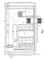
- the system 1 includes a horizontal work-plate 2 which may be identified as processing area provided with a plurality of rack openings 10 arranged side by side with respect to each other, each of which being adapted for accommodating elongated racks 3-8.
- Each rack opening 10 may be accessed by a slot-like aperture at a front side 11 of the system 1 allowing the racks 3-8 to be inserted into the rack openings 10 and removed therefrom, respectively.
- each rack 3-8 is provided with two lateral ribs 9 linearly extending in parallel relationship with respect to each other which, when inserting the racks 3-8 into the rack openings 10, get into fitting engagement with grooves formed by the work-plate 2 to slidably support the racks 3-8.
- the system 1 comprises a number of six racks 3-8 including a waste rack 3, a processing rack 4, a tip tray rack 5, a first reagent rack 6, a second reagent rack 7 and a bottle rack 8.
- Individual racks are being provided with a number of retaining sections 12 to accommodate and hold various objects such as multi-well plates, tip trays and bottle cartridges.
- the waste rack 3 is shown to be loaded with three waste tip trays 13 to receive waste tips and a waste liquid tray 14 to receive waste liquid
- the processing rack 4 is shown to be loaded with two processing plates 15 (deep-well plates) to receive nucleic acids containing fluids used as starting materials for the extraction of nucleic acids and two output plates 16 to receive solutions containing the extracted (purified) nucleic acids
- the tip tray rack 5 is provided with four tip trays 16 filled with tips
- the first and second reagent racks 6, 7 may be loaded with various processing solutions such as buffer and wash solutions (not further detailed in the figures) and are shown to be loaded with reagent plates 18 for mixing of reagent containing solutions
- the bottle rack 8 is provided with several bottle cartridges 19 for supporting of bottles 20 containing various liquids such as enzymes and suspensions of magnetic particles.
- the racks 3-8 are provided with plural consumables to be used for the automated extraction of nucleic acids which have to be manually or automatically preloaded prior to starting the extraction of nucleic acids.
- individual racks 3-8 can be partly or completely put out of the rack openings 10 for manual or automated loading and/or unloading operations as above-detailed.
- the processing rack 4 is shown to be partly pulled out of the rack opening 10.
- FIGS. 2 and 3 depict specific numbers of system components such as racks, retaining sections, plates, trays and bottle cartridges, it is to be understood that these numbers may vary in accord with specific needs for the extraction of nucleic acids.
- individual plates are provided with a planar array of 96 wells with 8 wells arranged side by side in a row extending in a first direction and 12 rows stacked one upon the other in a second direction, with the first and second directions being in orthogonal relationship with respect to each other.
- individual tip trays include 96 tips. It, however, is to be understood that differently sized arrays may alternatively be used in accordance with specific needs for the extraction of nucleic acids.
- the system 1 comprises a first pipettor 21 including 96 first pipettes 30 provided with disposable pipetting tips 22, adapted to transfer fluids to or from the plates. More specifically, the first pipettes 30 are mounted to a transfer head 29 of a positioning device 23 which can be moved in a first direction of travel towards and away from the work-plate 2, for instance by means of a spindle drive, and in second and third directions of travel in a plane, with the second and third directions being in orthogonal relationship with respect to the first direction, by means of first and second guiding rails 24, 25. Since such positioning device 23 is well-known to those of skill in the art, it is not further detailed herein.
- the first pipettor 21 can thus be moved relative to the racks 3-8 for pipetting of liquids for the automated processing of fluid samples.
- the system 1 further includes a second pipettor 26 including a plurality of second pipettes 31, adapted to transfer fluids to or from the plates, which is not further detailed herein.
- the system yet further includes a linear array 27 of eight ultrasonic sensors 28, adapted to determine the presence of objects by means of acoustic waves which are secured to the transfer head 29 and thus can be moved together with the first pipettor 21 with respect to the racks 3-8.
- the linearly arrayed ultrasonic sensors 28 extend along the same direction (first direction) as each row of individual plates, wherein a distance in-between adjacent ultrasonic sensors 28 matches a distance in-between adjacent wells.
- a programmable control computer 34 is used for controlling of the automated processing of nucleic acids containing fluids for the extraction of nucleic acids according to a predetermined process operation plan. Accordingly, the control computer 34 runs a computer-readable program which is provided with instructions to perform automated operations in accord with the process operation plan. In that, the control computer 34 is electrically connected to the system components which require control as specified by the process operation plan which include the positioning device 23 and the ultrasonic sensors 28. Data connection between the control computer 34 and the system components is by plural data connections (not illustrated) which can be part of a network for transferring data.
- the control computer 34 may be an off-the-shelf computer programmed to run the process operation plan for controlling the system 1.
- the process operation plan defines the consumables which are required for the automated extraction of nucleic acids and thus have to be preloaded in advance of starting the fluid handling steps.
- it defines intended positions (target positions) of consumables with respect to the racks 3-8 into which the consumables are to be placed when preloaded.
- It also defines intended positions (target positions) of consumables with respect to individual plates, trays and cartridges into which consumables such as tips and bottles are to be placed when preloaded.
- the process operation plan may optionally also define identity and/or orientation with respect to the intended position of individual consumables to be used for the automated extraction of nucleic acids.
- the control computer 34 further includes a display 35 for displaying graphical representations and/or messages to be read by the user.
- the control computer 34 can, e.g., include a key panel (not illustrated).
- the display 35 can, e.g., be embodied as touch-screen to display information and enter data.
- the system 1 further includes a pre-analytical processing device generally referred to at 36 for the processing of fluids located on the work-area 2.
- the processing device 36 e.g., includes heating and magnetic separation devices (not illustrated) for the automated extraction of nucleic acids. Since extraction of nucleic acids is well-known to those of skill in the art it is not further elucidated herein.
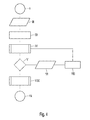
- FIG. 4 depicting a flow chart illustrating exemplary process steps for the processing of nucleic acids containing fluids according to the process operation plan.
- process step I e.g., when powering-up system 1, different process operation plans are displayed (process step II) on the display 35 for selection by a user.
- process step II displayed (process step II) on the display 35 for selection by a user.
- the user can select a process operation plan according to the specific operations to be performed for the processing of nucleic acids containing fluids (process step III).
- the process operation plan defines the consumables which are to be used for the processing of nucleic acids containing fluids, as well as target positions, identities and orientations with respect to the intended position of individual consumables. It may be provided that the user can also enter various process parameters for tailoring the process operation plan to specific needs.
- a subroutine "CHECK PRESENCE" (process step IV) starts.
- This subroutine starts a control run in which the sensor array 27 of ultrasonic sensors 28 is moved over the racks 3-8 to determine if consumables are present in their intended positions as defined by the process operation plan.
- the display 35 can, e.g., display the work-plate 2 or one or more parts thereof to visualize the consumables at their intended positions required for the processing of the fluids, i.e. extraction of nucleic acids. Hence, based on this visual information, the user can readily charge the system 1 with the required consumables. Charging of the system 1 with consumables can be performed by manual and/or automatic charging operations.
- the ultrasonic sensors 28 are moved over the intended locations of the tip trays 17 by means of the transfer head 29. Stated more particularly, when moving the ultrasonic sensors over the tip trays 17, first acoustic waves are generated and emitted towards the intended locations of the processing plates 17, with first signals (time between emission of acoustic waves and reception of reflected acoustic waves) of the reflected first acoustic waves being measured.
- At least one second acoustic wave is generated and emitted towards a predetermined surface (such as a dedicated reference surface) of the tip tray rack 5, with a second signal (time between emission of acoustic waves and reception of reflected acoustic waves) of the reflected second acoustic wave being measured.
- the determination of the presence of the tips contained in the tip trays 17 is similarly performed, except for emitting the at least one second acoustic wave towards a predetermined surface of each of the tip trays 17 and measuring second signals of the second acoustic waves reflected therefrom.
- first acoustic waves are generated and emitted towards the intended locations of the processing plates 15, with first signals (round-trip-times) of the reflected first acoustic waves being measured.
- second acoustic wave is generated and emitted towards a predetermined surface of the processing rack 4, with a second signal (round-trip-time) of the reflected second acoustic wave being measured.
- the determination of the presence of objects is analogously repeated for each of the consumables to be used for processing of nucleic acids containing fluids, with the presence of objects being either determined with respect to the rack to which it belongs or with respect to the plate, tray or cartridge to which it belongs.
- the determination of the presence of objects may be based on determining distances of the reflecting surfaces from the ultrasonic sensor based on the resulting round-trip-time (time-of-travel) measurements.
- This subroutine starts a control run in which the ultrasonic sensors 28 are moved over one or both of the processing plates 15 containing the nucleic acids containing fluids, in which the fluid levels are determined as detailed-below in connection with FIG. 6 .
- the racks 3-8 are kept stationary during determining the presence of consumables and fluid levels of the fluids contained in the processing plates 15.
- the first and second signals are compared with each other in calculating a difference of the first and second signals (round-trip times or distances).
- the difference of the signals then is compared with an intended difference of signals as defined by the process operation plan. In case the difference of signals matches the intended difference of signal amplitudes, it is assumed that the consumable concerned is in its target position.
- determined fluid levels of fluids contained in the processing plates 15 are compared with intended fluid levels as defined by the process operation plan. In case the fluid levels match the intended fluid levels, it is assumed that the fluid levels are correct.
- a message is displayed on the display 35 containing information guiding the user to load missing and/or misplaced disposables (process step VI).
- another message is displayed on the display 35 containing information guiding the user to load the missing fluids (process step VI).
- the display 35 can, e.g., display the work-plate 2 or one or more parts thereof in a manner to visualize a possible mismatch between the consumables actually present in the system 1 and the required consumables as defined by the process operation plan. Based on this visual information, the user can verify the result of the charging operation and can readily add missing consumables, e.g., by a manual charging operation.
- the user can re-start the subroutine "CHECK PRESENCE” and/or the subroutine "CHECK FLUID LEVELS” as desired actuating the control computer 34.
- process step VIII another subroutine "EXTRACTION" is started for performing the steps for extracting the nucleic acids which is not further detailed herein, which ends when purified nucleic acids have be obtained (process step IX).
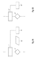
- subroutine "EXTRACTION” When performing the subroutine "EXTRACTION", subroutine "CHECK PRESENCE” as illustrated in FIG. 5A , and subroutine "CHECK FLUID LEVELS” as illustrated in FIG. 5B may be performed.
- the presence of consumables to be used for the processing of fluids in intended positions as defined by the process operation plan is controlled scanning the consumables by means of the ultrasonic sensors 28.
- an identity and/or orientation of individual consumables with respect to their intended positions as defined by the process operation plan may be performed, e.g., determining a geometric profile, in particular a height profile (height pattern), of individual objects which is compared with an intended profile for the consumable concerned.
- Intended signal values as defined by the process operation plan may be readily adapted in calibrating the ultrasonic sensor signals using reference surfaces of the racks and plates, respectively.
- FIG. 6 illustrating a diagram depicting a time-of-travel indicating curve for determining fluid levels in the output plate 16 using the sensor array 27 of the system 1.
- FIG. 6 indicates time-of-travel measurements of an ultrasonic sensor 28 which is continuously moved along the second direction (stacking direction of rows) as indicated by arrow 32 (see FIG. 1 ) of the output plate 16.
- the x-axis of this diagram is indicating a travel time of the positioning device which relates to a position on the process area given a reference/starting position of the positioning device and its velocity.
- the time-of-travel measurements are obtained in transmitting acoustic waves towards the output plate 16 and receiving the acoustic waves upon reflection to thereby determine a time interval between transmitted and received acoustic waves.
- the y-axis of this diagram depicts the turn-around time of an acoustic wave emitted by the ultrasonic sensor, reflected (vertically) from the location of the process area underneath and received by the ultrasonic sensor. Accordingly, a time-of-travel profile of the output plate 16 as seen by the ultrasonic sensor 28 is obtained.
- positions of individual wells along the second direction can be determined based on a detection of falling and rising edges with respect to a reference level (R0 to R12) which corresponds to the plane level of the output plate 16.
- R0 to R12 a reference level which corresponds to the plane level of the output plate 16.
- the sensor array 27 may be continuously moved along the first direction (direction according to which wells are arranged in individual rows) as indicated by arrow 33 (see FIG. 1 ) of the output plate 16. Yet alternatively, the sensor array 27 may be continuously moved to perform a combined movement along the first and second directions of the output plate 16.
- the outcome of pipetting operations may be efficiently controlled by fluid level detection, for instance, in performing pipetting operations when moving the transfer head 29 in one direction of travel and performing fluid levels detection when moving the transfer head 29 in an opposite direction of travel. More particularly, when determining fluid levels prior to pipetting operations and also after the pipetting operations, pipetted volumes may be determined. Basically, information obtained in scanning along one dimension can be considered sufficient in case consumables are symmetrically arranged along such scanning directions.
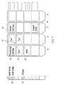
- FIG. 7 depicts an exemplary screen display of the display 35 of target positions of objects.
- a process operation plan according to this embodiment comprises a section for supporting the loading of objects onto the work-plate 2 of the system 1.
- the user of the control computer 34 selects a process operation plan from a menu.
- the process operation plan then continues and displays the objects to be loaded on a screen display as shown in FIG. 7 .
- the screen display is a schematic representation of the work-plate 2 as shown in figure 2 .
- Reference numerals in FIG. 7 have a dash to indicate that the numbers are used for screen representations of like objects in FIG. 2 .
- bottles 20' which are MGP bottles (i.e. bottles holding a suspension of magnetic glass particles) and DNAse reagent bottles (i.e. a DNA digesting reagent) into the indicated positions (target positions) in the bottle rack 8'.
- the first reagent rack 6' needs to be filled with the reagent plate 18' (processing cartridge) and two specific reagents 37'.
- the tip tray rack 5' needs to be filled with two tip trays 17' pre-filled with tips and the processing rack 4' is to be filled with the processing plate 15' (sample cartridge) and the output plate 16'.
- the control computer 34 proceeds with the process operation plan.
- it is checked with one or more ultrasonic sensors 28 if objects are present in the prescribed positions.
- it may be further checked by the profile of the objects if proper objects have been loaded. By this it can be for example detected when tips have been loaded in a position for reagents.
- Loading mistakes can be signalled to the user by e.g. text messages as "please load tips" or "sample cartridge is missing".
- a similar screen display as depicted in FIG. 7 can be employed to signal loading mistakes by colour coded representation of missing objects or misplaced objects. E.g. a missing tip tray can be depicted in red and flashing.
Landscapes
- Physics & Mathematics (AREA)
- Health & Medical Sciences (AREA)
- Life Sciences & Earth Sciences (AREA)
- Chemical & Material Sciences (AREA)
- Analytical Chemistry (AREA)
- Biochemistry (AREA)
- General Health & Medical Sciences (AREA)
- General Physics & Mathematics (AREA)
- Immunology (AREA)
- Pathology (AREA)
- Automatic Analysis And Handling Materials Therefor (AREA)
- Sampling And Sample Adjustment (AREA)
Priority Applications (1)
| Application Number | Priority Date | Filing Date | Title |
|---|---|---|---|
| EP09177280.6A EP2192412B1 (fr) | 2008-11-28 | 2009-11-26 | Portable object comprising a display and application performing electronic transactions |
Applications Claiming Priority (2)
| Application Number | Priority Date | Filing Date | Title |
|---|---|---|---|
| EP08170313 | 2008-11-28 | ||
| EP09177280.6A EP2192412B1 (fr) | 2008-11-28 | 2009-11-26 | Portable object comprising a display and application performing electronic transactions |
Publications (2)
| Publication Number | Publication Date |
|---|---|
| EP2192412A1 true EP2192412A1 (fr) | 2010-06-02 |
| EP2192412B1 EP2192412B1 (fr) | 2017-05-03 |
Family
ID=40527954
Family Applications (1)
| Application Number | Title | Priority Date | Filing Date |
|---|---|---|---|
| EP09177280.6A Active EP2192412B1 (fr) | 2008-11-28 | 2009-11-26 | Portable object comprising a display and application performing electronic transactions |
Country Status (3)
| Country | Link |
|---|---|
| US (2) | US9086396B2 (fr) |
| EP (1) | EP2192412B1 (fr) |
| ES (1) | ES2630213T3 (fr) |
Families Citing this family (12)
| Publication number | Priority date | Publication date | Assignee | Title |
|---|---|---|---|---|
| US8309036B2 (en) * | 2009-05-15 | 2012-11-13 | Gen-Probe Incorporated | Method for separating viscous materials suspended from a pipette |
| JP5600487B2 (ja) * | 2010-06-24 | 2014-10-01 | シスメックス株式会社 | 検体分析装置及び液体吸引方法 |
| JP6104810B2 (ja) * | 2010-11-23 | 2017-03-29 | アンドリュー・アライアンス・ソシエテ・アノニムAndrew Alliance S.A. | ピペットのプログラミング可能な操作のための装置及び方法 |
| JP6189179B2 (ja) * | 2013-11-01 | 2017-08-30 | シスメックス株式会社 | 容器洗浄装置および分析装置 |
| WO2015092844A1 (fr) * | 2013-12-16 | 2015-06-25 | 株式会社島津製作所 | Dispositif de collecte de liquide et analyseur automatisé disposé avec celui-ci |
| US10465232B1 (en) * | 2015-10-08 | 2019-11-05 | Trace Genomics, Inc. | Methods for quantifying efficiency of nucleic acid extraction and detection |
| WO2019005744A1 (fr) * | 2017-06-26 | 2019-01-03 | Luedemann Hans Christian | Dispositif de transfert de liquide à capteur intégré de distance et de hauteur de remplissage de liquide sans contact, et procédés |
| DE102019110094A1 (de) * | 2019-04-17 | 2020-10-22 | Analytik Jena Ag | Verfahren zur Bestimmung des Verbrauchs zumindest einer Substanz |
| WO2021002105A1 (fr) * | 2019-07-02 | 2021-01-07 | 株式会社堀場アドバンスドテクノ | Dispositif d'analyse d'échantillon biologique et procédé d'analyse d'échantillon biologique |
| AU2021259791B2 (en) | 2020-04-24 | 2025-12-04 | Gen-Probe Incorporated | System and method for differential measurement of a fluid level in a sample receptacle |
| CN113188843B (zh) * | 2021-05-10 | 2022-09-02 | 江西怡杉环保股份有限公司 | 一种水质采样设备 |
| CN119901356A (zh) * | 2025-01-20 | 2025-04-29 | 艾康生物技术(杭州)有限公司 | 液位测量装置 |
Citations (5)
| Publication number | Priority date | Publication date | Assignee | Title |
|---|---|---|---|---|
| EP0979998A2 (fr) * | 1998-07-14 | 2000-02-16 | Bayer Corporation | Détection dynamique et non invasive des charactéristiques de récipients d'analyse |
| EP0979999A2 (fr) * | 1998-07-14 | 2000-02-16 | Bayer Corporation | Dispositif automatique pour l'introduction et l'éjection de récipients dans une analysateur |
| EP0732598B1 (fr) | 1995-03-15 | 2001-05-16 | SANYO ELECTRIC Co., Ltd. | Senseur à ultrasons et appareil de pipettage utilisant un tel senseur |
| US20080050289A1 (en) * | 1998-10-28 | 2008-02-28 | Laugharn James A Jr | Apparatus and methods for controlling sonic treatment |
| EP1975629A1 (fr) * | 2007-03-30 | 2008-10-01 | F.Hoffmann-La Roche Ag | Procédé et appareil pour détecter le contact d'une aiguille de pipetage avec un liquide dans un récipient |
Family Cites Families (34)
| Publication number | Priority date | Publication date | Assignee | Title |
|---|---|---|---|---|
| AU670449B2 (en) * | 1992-06-08 | 1996-07-18 | Behring Diagnostics Inc. | Liquid dispensing system |
| AU3651497A (en) * | 1996-07-05 | 1998-02-02 | Beckman Coulter, Inc. | Automated sample processing system |
| US6200287B1 (en) * | 1997-09-05 | 2001-03-13 | Gambro, Inc. | Extracorporeal blood processing methods and apparatus |
| JP2002532717A (ja) * | 1998-12-11 | 2002-10-02 | サイミックス テクノロジーズ、インク | 迅速な物質特性評価のためのセンサ配列に基づくシステム及びその方法 |
| US6086821A (en) * | 1999-03-29 | 2000-07-11 | The United States Of America As Represented By The Secretary Of The Navy | Ultrasonic force differentiation assay |
| WO2000068675A1 (fr) * | 1999-05-10 | 2000-11-16 | California Institute Of Technology | Utilisation d'un comportement de reponse spatio-temporelle dans des groupements de capteurs pour detecter des analytes dans des fluides |
| WO2001066172A2 (fr) * | 2000-03-09 | 2001-09-13 | Gambro, Inc. | Technique et dispositif de traitement extra-corporel du sang |
| US6878346B2 (en) * | 2002-05-17 | 2005-04-12 | Bayer Corporation | Serum transfer cup |
| JP3733123B2 (ja) | 2003-04-14 | 2006-01-11 | アロカ株式会社 | 容器検出装置 |
| US7618589B2 (en) * | 2004-09-07 | 2009-11-17 | Hitachi Koki Co., Ltd. | Automatic dispenser |
| EP1866653A4 (fr) * | 2005-03-07 | 2009-08-26 | Novx Systems Inc | Analyseur automatise |
| US7749445B2 (en) * | 2005-05-02 | 2010-07-06 | Bioscale, Inc. | Method and apparatus for analyzing bioprocess fluids |
| US7611908B2 (en) * | 2005-05-02 | 2009-11-03 | Bioscale, Inc. | Method and apparatus for therapeutic drug monitoring using an acoustic device |
| US7648844B2 (en) * | 2005-05-02 | 2010-01-19 | Bioscale, Inc. | Method and apparatus for detection of analyte using an acoustic device |
| US8932542B2 (en) | 2005-09-26 | 2015-01-13 | Qiagen Gmbh | Apparatus for processing biological material |
| JP4724570B2 (ja) * | 2006-02-20 | 2011-07-13 | 武蔵エンジニアリング株式会社 | 液体移送装置 |
| WO2008016691A2 (fr) * | 2006-08-01 | 2008-02-07 | Covaris, Inc. | Procédés et appareils pour traiter des échantillons par de l'énergie acoustique |
| EP2069750B1 (fr) * | 2006-08-15 | 2014-07-02 | Cytyc Corporation | Système d'incorporation de bloc de cellules |
| JP2008058163A (ja) * | 2006-08-31 | 2008-03-13 | Hitachi High-Technologies Corp | 自動分析装置 |
| EP1975626A1 (fr) | 2007-03-29 | 2008-10-01 | F. Hoffmann-Roche AG | Empileuse pour des plaques à microtitre |
| US8357538B2 (en) * | 2007-04-06 | 2013-01-22 | Qiagen Gaithersburg, Inc. | Automated assay and system |
| US8703492B2 (en) * | 2007-04-06 | 2014-04-22 | Qiagen Gaithersburg, Inc. | Open platform hybrid manual-automated sample processing system |
| US7985375B2 (en) * | 2007-04-06 | 2011-07-26 | Qiagen Gaithersburg, Inc. | Sample preparation system and method for processing clinical specimens |
| US7770475B2 (en) * | 2007-06-29 | 2010-08-10 | Rainin Instrument, Llc | Hybrid manual-electronic pipette |
| EP2017618A1 (fr) * | 2007-07-20 | 2009-01-21 | Koninklijke Philips Electronics N.V. | Procédé et systèmes pour la détection |
| EP2017006A1 (fr) * | 2007-07-20 | 2009-01-21 | Koninklijke Philips Electronics N.V. | Procédés microfluidiques et systèmes servant à détecter des analytes |
| CN101925817B (zh) * | 2008-01-22 | 2016-01-13 | 皇家飞利浦电子股份有限公司 | 利用指示剂颗粒检测靶成分 |
| JP5628784B2 (ja) * | 2008-03-17 | 2014-11-19 | コーニンクレッカ フィリップス エヌ ヴェ | 磁性粒子によるアッセイ用カートリッジ |
| US20090246085A1 (en) * | 2008-03-31 | 2009-10-01 | Helicos Biosciences Corporation | Liquid Handling System and Methods for Mixing and Delivering Liquid Reagents |
| ITMO20080159A1 (it) * | 2008-05-27 | 2009-11-28 | Gambro Lundia Ab | Circuito fluido medicale. |
| EP2473284A1 (fr) * | 2009-09-01 | 2012-07-11 | Koninklijke Philips Electronics N.V. | Dispositif de filtration de fluide |
| WO2011133450A2 (fr) * | 2010-04-19 | 2011-10-27 | Meso Scale Technologies, Llc. | Dosages sérologiques |
| JP5600487B2 (ja) * | 2010-06-24 | 2014-10-01 | シスメックス株式会社 | 検体分析装置及び液体吸引方法 |
| US20130109030A1 (en) * | 2010-07-05 | 2013-05-02 | Koninklijke Philips Electronics N.V. | Examination system with sample incubation |
-
2009
- 2009-11-23 US US12/623,797 patent/US9086396B2/en active Active
- 2009-11-26 ES ES09177280.6T patent/ES2630213T3/es active Active
- 2009-11-26 EP EP09177280.6A patent/EP2192412B1/fr active Active
-
2015
- 2015-06-11 US US14/737,462 patent/US9377479B2/en active Active
Patent Citations (5)
| Publication number | Priority date | Publication date | Assignee | Title |
|---|---|---|---|---|
| EP0732598B1 (fr) | 1995-03-15 | 2001-05-16 | SANYO ELECTRIC Co., Ltd. | Senseur à ultrasons et appareil de pipettage utilisant un tel senseur |
| EP0979998A2 (fr) * | 1998-07-14 | 2000-02-16 | Bayer Corporation | Détection dynamique et non invasive des charactéristiques de récipients d'analyse |
| EP0979999A2 (fr) * | 1998-07-14 | 2000-02-16 | Bayer Corporation | Dispositif automatique pour l'introduction et l'éjection de récipients dans une analysateur |
| US20080050289A1 (en) * | 1998-10-28 | 2008-02-28 | Laugharn James A Jr | Apparatus and methods for controlling sonic treatment |
| EP1975629A1 (fr) * | 2007-03-30 | 2008-10-01 | F.Hoffmann-La Roche Ag | Procédé et appareil pour détecter le contact d'une aiguille de pipetage avec un liquide dans un récipient |
Also Published As
| Publication number | Publication date |
|---|---|
| EP2192412B1 (fr) | 2017-05-03 |
| US9377479B2 (en) | 2016-06-28 |
| ES2630213T3 (es) | 2017-08-18 |
| US20100132438A1 (en) | 2010-06-03 |
| US20150276779A1 (en) | 2015-10-01 |
| US9086396B2 (en) | 2015-07-21 |
Similar Documents
| Publication | Publication Date | Title |
|---|---|---|
| EP2192412B1 (fr) | Portable object comprising a display and application performing electronic transactions | |
| US7666355B2 (en) | Automated analyzer | |
| US8163239B2 (en) | Sample analyzer | |
| EP2335078B1 (fr) | Appareil pour réaliser automatiquement des analyses | |
| CN101135692B (zh) | 自动分析装置 | |
| CN103217536B (zh) | 试样分析装置及试样分析方法 | |
| US9581608B2 (en) | Sample analyzer and method for controlling sample analyzer | |
| US20230258676A1 (en) | Automated analytical system for processing biological samples | |
| EP0431578A2 (fr) | Procédé de vérification de la précision d'un distributeur de liquide | |
| EP2019321A1 (fr) | Équipement de nettoyage et analyseur automatique | |
| JP4819324B2 (ja) | 同心のロータを備えたアナライザ | |
| EP2207039A2 (fr) | Procédé et système de mesure de volumes de liquides pour contrôler les procédés de pipetage | |
| EP2589965B1 (fr) | Dispositif d'analyse de spécimen | |
| EP2402764B1 (fr) | Distribution d'échantillons | |
| EP2075587B1 (fr) | Analyseur automatique et son procédé de distribution | |
| CN112534270A (zh) | 操作实验室仪器的方法 | |
| WO2016017291A1 (fr) | Dispositif d'analyse automatique | |
| JP2019100894A (ja) | 自動分析装置および自動分析方法 | |
| EP4357785A1 (fr) | Instrument de laboratoire | |
| EP4549955A1 (fr) | Système automatisé de regroupement d'échantillons et procédé de regroupement d'échantillons l'utilisant | |
| EP2177913A1 (fr) | Instrument de laboratoire avec une surveillance de fonction |
Legal Events
| Date | Code | Title | Description |
|---|---|---|---|
| PUAI | Public reference made under article 153(3) epc to a published international application that has entered the european phase |
Free format text: ORIGINAL CODE: 0009012 |
|
| AK | Designated contracting states |
Kind code of ref document: A1 Designated state(s): AT BE BG CH CY CZ DE DK EE ES FI FR GB GR HR HU IE IS IT LI LT LU LV MC MK MT NL NO PL PT RO SE SI SK SM TR |
|
| AX | Request for extension of the european patent |
Extension state: AL BA RS |
|
| 17P | Request for examination filed |
Effective date: 20100719 |
|
| GRAP | Despatch of communication of intention to grant a patent |
Free format text: ORIGINAL CODE: EPIDOSNIGR1 |
|
| STAA | Information on the status of an ep patent application or granted ep patent |
Free format text: STATUS: GRANT OF PATENT IS INTENDED |
|
| INTG | Intention to grant announced |
Effective date: 20161215 |
|
| GRAJ | Information related to disapproval of communication of intention to grant by the applicant or resumption of examination proceedings by the epo deleted |
Free format text: ORIGINAL CODE: EPIDOSDIGR1 |
|
| STAA | Information on the status of an ep patent application or granted ep patent |
Free format text: STATUS: REQUEST FOR EXAMINATION WAS MADE |
|
| GRAR | Information related to intention to grant a patent recorded |
Free format text: ORIGINAL CODE: EPIDOSNIGR71 |
|
| GRAS | Grant fee paid |
Free format text: ORIGINAL CODE: EPIDOSNIGR3 |
|
| STAA | Information on the status of an ep patent application or granted ep patent |
Free format text: STATUS: GRANT OF PATENT IS INTENDED |
|
| GRAA | (expected) grant |
Free format text: ORIGINAL CODE: 0009210 |
|
| STAA | Information on the status of an ep patent application or granted ep patent |
Free format text: STATUS: THE PATENT HAS BEEN GRANTED |
|
| INTC | Intention to grant announced (deleted) | ||
| AK | Designated contracting states |
Kind code of ref document: B1 Designated state(s): AT BE BG CH CY CZ DE DK EE ES FI FR GB GR HR HU IE IS IT LI LT LU LV MC MK MT NL NO PL PT RO SE SI SK SM TR |
|
| INTG | Intention to grant announced |
Effective date: 20170327 |
|
| REG | Reference to a national code |
Ref country code: GB Ref legal event code: FG4D |
|
| REG | Reference to a national code |
Ref country code: AT Ref legal event code: REF Ref document number: 890573 Country of ref document: AT Kind code of ref document: T Effective date: 20170515 Ref country code: CH Ref legal event code: EP |
|
| REG | Reference to a national code |
Ref country code: IE Ref legal event code: FG4D |
|
| REG | Reference to a national code |
Ref country code: DE Ref legal event code: R096 Ref document number: 602009045816 Country of ref document: DE |
|
| REG | Reference to a national code |
Ref country code: ES Ref legal event code: FG2A Ref document number: 2630213 Country of ref document: ES Kind code of ref document: T3 Effective date: 20170818 |
|
| REG | Reference to a national code |
Ref country code: NL Ref legal event code: MP Effective date: 20170503 |
|
| REG | Reference to a national code |
Ref country code: AT Ref legal event code: MK05 Ref document number: 890573 Country of ref document: AT Kind code of ref document: T Effective date: 20170503 |
|
| REG | Reference to a national code |
Ref country code: LT Ref legal event code: MG4D |
|
| REG | Reference to a national code |
Ref country code: FR Ref legal event code: PLFP Year of fee payment: 9 |
|
| PG25 | Lapsed in a contracting state [announced via postgrant information from national office to epo] |
Ref country code: AT Free format text: LAPSE BECAUSE OF FAILURE TO SUBMIT A TRANSLATION OF THE DESCRIPTION OR TO PAY THE FEE WITHIN THE PRESCRIBED TIME-LIMIT Effective date: 20170503 Ref country code: HR Free format text: LAPSE BECAUSE OF FAILURE TO SUBMIT A TRANSLATION OF THE DESCRIPTION OR TO PAY THE FEE WITHIN THE PRESCRIBED TIME-LIMIT Effective date: 20170503 Ref country code: GR Free format text: LAPSE BECAUSE OF FAILURE TO SUBMIT A TRANSLATION OF THE DESCRIPTION OR TO PAY THE FEE WITHIN THE PRESCRIBED TIME-LIMIT Effective date: 20170804 Ref country code: LT Free format text: LAPSE BECAUSE OF FAILURE TO SUBMIT A TRANSLATION OF THE DESCRIPTION OR TO PAY THE FEE WITHIN THE PRESCRIBED TIME-LIMIT Effective date: 20170503 Ref country code: FI Free format text: LAPSE BECAUSE OF FAILURE TO SUBMIT A TRANSLATION OF THE DESCRIPTION OR TO PAY THE FEE WITHIN THE PRESCRIBED TIME-LIMIT Effective date: 20170503 Ref country code: NO Free format text: LAPSE BECAUSE OF FAILURE TO SUBMIT A TRANSLATION OF THE DESCRIPTION OR TO PAY THE FEE WITHIN THE PRESCRIBED TIME-LIMIT Effective date: 20170803 |
|
| PG25 | Lapsed in a contracting state [announced via postgrant information from national office to epo] |
Ref country code: PL Free format text: LAPSE BECAUSE OF FAILURE TO SUBMIT A TRANSLATION OF THE DESCRIPTION OR TO PAY THE FEE WITHIN THE PRESCRIBED TIME-LIMIT Effective date: 20170503 Ref country code: NL Free format text: LAPSE BECAUSE OF FAILURE TO SUBMIT A TRANSLATION OF THE DESCRIPTION OR TO PAY THE FEE WITHIN THE PRESCRIBED TIME-LIMIT Effective date: 20170503 Ref country code: BG Free format text: LAPSE BECAUSE OF FAILURE TO SUBMIT A TRANSLATION OF THE DESCRIPTION OR TO PAY THE FEE WITHIN THE PRESCRIBED TIME-LIMIT Effective date: 20170803 Ref country code: IS Free format text: LAPSE BECAUSE OF FAILURE TO SUBMIT A TRANSLATION OF THE DESCRIPTION OR TO PAY THE FEE WITHIN THE PRESCRIBED TIME-LIMIT Effective date: 20170903 Ref country code: LV Free format text: LAPSE BECAUSE OF FAILURE TO SUBMIT A TRANSLATION OF THE DESCRIPTION OR TO PAY THE FEE WITHIN THE PRESCRIBED TIME-LIMIT Effective date: 20170503 Ref country code: SE Free format text: LAPSE BECAUSE OF FAILURE TO SUBMIT A TRANSLATION OF THE DESCRIPTION OR TO PAY THE FEE WITHIN THE PRESCRIBED TIME-LIMIT Effective date: 20170503 |
|
| PG25 | Lapsed in a contracting state [announced via postgrant information from national office to epo] |
Ref country code: CZ Free format text: LAPSE BECAUSE OF FAILURE TO SUBMIT A TRANSLATION OF THE DESCRIPTION OR TO PAY THE FEE WITHIN THE PRESCRIBED TIME-LIMIT Effective date: 20170503 Ref country code: RO Free format text: LAPSE BECAUSE OF FAILURE TO SUBMIT A TRANSLATION OF THE DESCRIPTION OR TO PAY THE FEE WITHIN THE PRESCRIBED TIME-LIMIT Effective date: 20170503 Ref country code: DK Free format text: LAPSE BECAUSE OF FAILURE TO SUBMIT A TRANSLATION OF THE DESCRIPTION OR TO PAY THE FEE WITHIN THE PRESCRIBED TIME-LIMIT Effective date: 20170503 Ref country code: SK Free format text: LAPSE BECAUSE OF FAILURE TO SUBMIT A TRANSLATION OF THE DESCRIPTION OR TO PAY THE FEE WITHIN THE PRESCRIBED TIME-LIMIT Effective date: 20170503 Ref country code: EE Free format text: LAPSE BECAUSE OF FAILURE TO SUBMIT A TRANSLATION OF THE DESCRIPTION OR TO PAY THE FEE WITHIN THE PRESCRIBED TIME-LIMIT Effective date: 20170503 |
|
| REG | Reference to a national code |
Ref country code: DE Ref legal event code: R097 Ref document number: 602009045816 Country of ref document: DE |
|
| PG25 | Lapsed in a contracting state [announced via postgrant information from national office to epo] |
Ref country code: SM Free format text: LAPSE BECAUSE OF FAILURE TO SUBMIT A TRANSLATION OF THE DESCRIPTION OR TO PAY THE FEE WITHIN THE PRESCRIBED TIME-LIMIT Effective date: 20170503 |
|
| PLBE | No opposition filed within time limit |
Free format text: ORIGINAL CODE: 0009261 |
|
| STAA | Information on the status of an ep patent application or granted ep patent |
Free format text: STATUS: NO OPPOSITION FILED WITHIN TIME LIMIT |
|
| 26N | No opposition filed |
Effective date: 20180206 |
|
| PG25 | Lapsed in a contracting state [announced via postgrant information from national office to epo] |
Ref country code: SI Free format text: LAPSE BECAUSE OF FAILURE TO SUBMIT A TRANSLATION OF THE DESCRIPTION OR TO PAY THE FEE WITHIN THE PRESCRIBED TIME-LIMIT Effective date: 20170503 |
|
| PG25 | Lapsed in a contracting state [announced via postgrant information from national office to epo] |
Ref country code: MC Free format text: LAPSE BECAUSE OF FAILURE TO SUBMIT A TRANSLATION OF THE DESCRIPTION OR TO PAY THE FEE WITHIN THE PRESCRIBED TIME-LIMIT Effective date: 20170503 |
|
| PG25 | Lapsed in a contracting state [announced via postgrant information from national office to epo] |
Ref country code: LU Free format text: LAPSE BECAUSE OF NON-PAYMENT OF DUE FEES Effective date: 20171126 |
|
| REG | Reference to a national code |
Ref country code: BE Ref legal event code: MM Effective date: 20171130 |
|
| REG | Reference to a national code |
Ref country code: IE Ref legal event code: MM4A |
|
| PG25 | Lapsed in a contracting state [announced via postgrant information from national office to epo] |
Ref country code: MT Free format text: LAPSE BECAUSE OF NON-PAYMENT OF DUE FEES Effective date: 20171126 |
|
| REG | Reference to a national code |
Ref country code: FR Ref legal event code: PLFP Year of fee payment: 10 |
|
| PG25 | Lapsed in a contracting state [announced via postgrant information from national office to epo] |
Ref country code: IE Free format text: LAPSE BECAUSE OF NON-PAYMENT OF DUE FEES Effective date: 20171126 |
|
| PG25 | Lapsed in a contracting state [announced via postgrant information from national office to epo] |
Ref country code: BE Free format text: LAPSE BECAUSE OF NON-PAYMENT OF DUE FEES Effective date: 20171130 |
|
| PG25 | Lapsed in a contracting state [announced via postgrant information from national office to epo] |
Ref country code: HU Free format text: LAPSE BECAUSE OF FAILURE TO SUBMIT A TRANSLATION OF THE DESCRIPTION OR TO PAY THE FEE WITHIN THE PRESCRIBED TIME-LIMIT; INVALID AB INITIO Effective date: 20091126 |
|
| PG25 | Lapsed in a contracting state [announced via postgrant information from national office to epo] |
Ref country code: CY Free format text: LAPSE BECAUSE OF NON-PAYMENT OF DUE FEES Effective date: 20170503 |
|
| PG25 | Lapsed in a contracting state [announced via postgrant information from national office to epo] |
Ref country code: MK Free format text: LAPSE BECAUSE OF FAILURE TO SUBMIT A TRANSLATION OF THE DESCRIPTION OR TO PAY THE FEE WITHIN THE PRESCRIBED TIME-LIMIT Effective date: 20170503 |
|
| PG25 | Lapsed in a contracting state [announced via postgrant information from national office to epo] |
Ref country code: TR Free format text: LAPSE BECAUSE OF FAILURE TO SUBMIT A TRANSLATION OF THE DESCRIPTION OR TO PAY THE FEE WITHIN THE PRESCRIBED TIME-LIMIT Effective date: 20170503 |
|
| PG25 | Lapsed in a contracting state [announced via postgrant information from national office to epo] |
Ref country code: PT Free format text: LAPSE BECAUSE OF FAILURE TO SUBMIT A TRANSLATION OF THE DESCRIPTION OR TO PAY THE FEE WITHIN THE PRESCRIBED TIME-LIMIT Effective date: 20170503 |
|
| REG | Reference to a national code |
Ref country code: CH Ref legal event code: U11 Free format text: ST27 STATUS EVENT CODE: U-0-0-U10-U11 (AS PROVIDED BY THE NATIONAL OFFICE) Effective date: 20251201 |
|
| PGFP | Annual fee paid to national office [announced via postgrant information from national office to epo] |
Ref country code: DE Payment date: 20251022 Year of fee payment: 17 |
|
| PGFP | Annual fee paid to national office [announced via postgrant information from national office to epo] |
Ref country code: GB Payment date: 20251023 Year of fee payment: 17 |
|
| PGFP | Annual fee paid to national office [announced via postgrant information from national office to epo] |
Ref country code: IT Payment date: 20251022 Year of fee payment: 17 |
|
| PGFP | Annual fee paid to national office [announced via postgrant information from national office to epo] |
Ref country code: FR Payment date: 20251022 Year of fee payment: 17 |
|
| PGFP | Annual fee paid to national office [announced via postgrant information from national office to epo] |
Ref country code: CH Payment date: 20251201 Year of fee payment: 17 |
|
| PGFP | Annual fee paid to national office [announced via postgrant information from national office to epo] |
Ref country code: ES Payment date: 20251201 Year of fee payment: 17 |