EP2192468A1 - Installation de pédale destinée à la commande d'une pédale d'un véhicule automobile du côté passager - Google Patents
Installation de pédale destinée à la commande d'une pédale d'un véhicule automobile du côté passager Download PDFInfo
- Publication number
- EP2192468A1 EP2192468A1 EP08170198A EP08170198A EP2192468A1 EP 2192468 A1 EP2192468 A1 EP 2192468A1 EP 08170198 A EP08170198 A EP 08170198A EP 08170198 A EP08170198 A EP 08170198A EP 2192468 A1 EP2192468 A1 EP 2192468A1
- Authority
- EP
- European Patent Office
- Prior art keywords
- pedal
- passenger
- cable
- unit
- pedal lever
- Prior art date
- Legal status (The legal status is an assumption and is not a legal conclusion. Google has not performed a legal analysis and makes no representation as to the accuracy of the status listed.)
- Withdrawn
Links
- 230000005540 biological transmission Effects 0.000 claims abstract description 52
- 230000033001 locomotion Effects 0.000 claims description 11
- 230000000881 depressing effect Effects 0.000 claims description 10
- 230000000694 effects Effects 0.000 claims description 5
- 230000008878 coupling Effects 0.000 claims description 2
- 238000010168 coupling process Methods 0.000 claims description 2
- 238000005859 coupling reaction Methods 0.000 claims description 2
- 238000005096 rolling process Methods 0.000 abstract description 5
- 238000007665 sagging Methods 0.000 description 7
- 230000002349 favourable effect Effects 0.000 description 4
- 230000000994 depressogenic effect Effects 0.000 description 2
- 206010039203 Road traffic accident Diseases 0.000 description 1
- 230000000712 assembly Effects 0.000 description 1
- 238000000429 assembly Methods 0.000 description 1
- 230000000903 blocking effect Effects 0.000 description 1
- 238000005516 engineering process Methods 0.000 description 1
- 238000002347 injection Methods 0.000 description 1
- 239000007924 injection Substances 0.000 description 1
- 238000009434 installation Methods 0.000 description 1
- 239000002655 kraft paper Substances 0.000 description 1
- 238000012423 maintenance Methods 0.000 description 1
- 239000004033 plastic Substances 0.000 description 1
- 210000001747 pupil Anatomy 0.000 description 1
- 231100000241 scar Toxicity 0.000 description 1
Images


Classifications
-
- G—PHYSICS
- G05—CONTROLLING; REGULATING
- G05G—CONTROL DEVICES OR SYSTEMS INSOFAR AS CHARACTERISED BY MECHANICAL FEATURES ONLY
- G05G1/00—Controlling members, e.g. knobs or handles; Assemblies or arrangements thereof; Indicating position of controlling members
- G05G1/30—Controlling members actuated by foot
- G05G1/34—Double foot controls, e.g. for instruction vehicles
-
- G—PHYSICS
- G05—CONTROLLING; REGULATING
- G05G—CONTROL DEVICES OR SYSTEMS INSOFAR AS CHARACTERISED BY MECHANICAL FEATURES ONLY
- G05G7/00—Manually-actuated control mechanisms provided with one single controlling member co-operating with one single controlled member; Details thereof
- G05G7/02—Manually-actuated control mechanisms provided with one single controlling member co-operating with one single controlled member; Details thereof characterised by special provisions for conveying or converting motion, or for acting at a distance
- G05G7/04—Manually-actuated control mechanisms provided with one single controlling member co-operating with one single controlled member; Details thereof characterised by special provisions for conveying or converting motion, or for acting at a distance altering the ratio of motion or force between controlling member and controlled member as a function of the position of the controlling member
Definitions
- the present invention relates to a pedal system for operating a vehicle pedal of a motor vehicle from the passenger side according to claim 1.
- the force transmission unit is designed to exert a force on a force transmission element when depressing the passenger pedal lever and to convert the force exerted by means of a wheel-shaped force receiving element into a rotational force about the axis of rotation in order to drive the axis of rotation.
- a simple drive device for moving the roll of the retractor can be created, which allows a compact design of the pedal system.
- the power transmission unit may comprise a chain or belt-shaped tensile force transmitting element, one end of which is couplable to the passenger pedal lever and the other end of which can be fastened to a housing of the pedal system by train by means of an elastic retraction element.
- this tensile force transmission element is thus kept small and space-saving. Nevertheless, it can be ensured by the use of the elastic retraction element that, when the passenger pedal lever is released, the elements of the power transmission unit return to the starting position.
- a simple configuration of the rope retracting unit may be realized in a manner in which the cable retracting unit has a cable retracting member movably mounted on the passenger pedal lever, the cable retracting unit being adapted to move the roller of the retracting unit by movement of the cable retracting member relative to the passenger pedal lever cause.
- the cable retracting unit has a cable retracting member movably mounted on the passenger pedal lever, the cable retracting unit being adapted to move the roller of the retracting unit by movement of the cable retracting member relative to the passenger pedal lever cause.
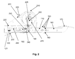
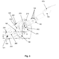
- a component arrangement includes a passenger pedal lever 110 rotatably mounted at a pivot 120 and a spring 121 (not shown) to a housing 130 (which may also be merely an open pedal bracket).
- the spring 121 which may be, for example, a coil spring, may serve to return the passenger pedal lever 110 after depression in the rest position.
- On the passenger pedal lever 110 at a head end 140, a hole pattern 150 is provided, via which a pedal lever 160 by means of contact pins and a foot plate 170 in various positions is fastened. In this way, the pedal system 100 is very flexible to install in different school vehicles and still provides good comfort in the operation by a driving instructor.
- a chain block member 180 is rotatably mounted, to which in turn one end of a chain 190 is fixed.
- the chain 190 can be guided via a gear 200, which is connected directly or via a gear with a about an axis of rotation 205 rotatably mounted pulley 210 with respect to a power transmission.
- a cable 220 is attached (which, for example, the inner cable of a Bowden cable forms), by means of which a corresponding pedal on the driver's side of the vehicle can be pulled down.
- the cable 220 may leave the housing 130 of the pedal system 100 at various positions 230.
- the chain block element 180 may also be referred to as a cable retraction element due to its functionality and may be configured such that a driver pin 240 engages in a recess 250 of this element 180 and "entrains" this element 180 upon depression of the passenger pedal lever 110 (ie in a corresponding position) Position fixed relative to the passenger pedal lever 110) and the chain block member 180 in the return of the passenger pedal lever 110 releases to its original position.
- the pedal assembly 100 may further include a spring member 260 (which may be another suitable elastic member such as a rubber) attached to the housing 130 and, for example, a lower portion (as viewed in the depressing direction) on the chain block member 180.
- a spring member 260 which may be another suitable elastic member such as a rubber
- the gear 200 drives in particular via a rigid connection directly to the axis or scar of the pulley 210, so that even a transmission gear can be omitted, which would require additional space.
- a correspondingly suitable transmission gear can be used to improve the required power or the required train.
- a rotation of the pulley 210 counterclockwise required In order to exert a pulling force from the pulley 210 on the rope 220, according to the arrangement Fig. 1 a rotation of the pulley 210 counterclockwise required. This can be done with a rigid connection between Gear 200 and pulley 210 can be achieved simply by a clever choice of chain guide the chain 190, according to the FIGS. 1 to 3 between the rotation axis 205 and the pivot point 120, a tensile force from the passenger pedal lever 110 and the chain block element 180 to the gear 200 exerts.
- an in Figure 1 to 3 not shown spring element (which may not necessarily be a mechanical spring, but also another elastic element such as a rubber) can be used, which is attached to a further end 270 of the chain 190 and this further end 270, for example, at an abutment point on the housing 130th the pedal system 100 attached to train.
- spring element which may not necessarily be a mechanical spring, but also another elastic element such as a rubber
- this further end 270 for example, at an abutment point on the housing 130th the pedal system 100 attached to train.
- the elastic spring element 260 should as far as possible on a (lower) edge of the cable retraction element 180 and as far away (for example, in the region of half of the cable retraction element 180 in extension to the passenger pedal lever 110) of a rotatable attachment point of the cable retraction element 180 attack on the passenger pedal lever 110.
- rope retraction element 180 can also be used not shown in the corresponding figures of the spring element, which is directly attached to the pulley 210 and causes a corresponding rolling movement of the pulley 210 at a non-penetrated passenger pedal lever 110.
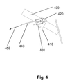
- FIG. 4 shows a side view of a driver's pedal 400 in the footwell of the driver's area of the motor vehicle.
- a pedal rider 410 is attached, which is shaped as a U-part, and is clamped on the pedal arm.
- a bolt 420 is attached, to which in turn a Seilklemmung is attached, which is movably mounted on the bolt.
- the cable 440 and 220 is fixed, which comes from the pulley from the adapter to the vehicle injection wall.
- the rope 220 and 440 is rolled up onto the roller 210 and a pulling force in the direction 450 is exerted on the driver pedal 400, whereby this driver pedal 400 is pulled down.
- FIG. 5 shows a side view of the driver's pedal 400 and 500 and a further attachment possibility of Seilzugiser 510 in the footwell of the driver area.
- the Seilzugiser can be a Bowden cable.
- the Seilzugiser with the cable guide 510 ie, the outer sheath of the Bowden cable
- the cable 220 can then be continued and secured with a cable clamp 540 and a bolt 550 around which the cable clamp is movably mounted.
- the bolt 550 can be attached to an adapter 560, in particular welded, which is attached, for example, at the bottom of the footwell of the driver's area of the vehicle. In this way not only can the cable 220 be fastened to the driver's pedal, but it is also possible to fasten a stable outer sheath of the cable-pulling unit to the driver's pedal without suffering any loss of the action of the
- the cable 220 can also be rotatably attached to the driver's pedal and can if possible be guided over a deflection roller, on the one hand the frictional resistance between cable 220 and a cable guide (not shown) As low as possible and the rope caused by the rotatable attachment to the driver's pedal no large rope loops.
- the proposed pedal system allows a variable output of the rope from the housing of the pedal system, which improves the connection of the Bowden cable, so that the installation flexibility of the pedal system over conventional pedal systems is greatly increased.
Landscapes
- Physics & Mathematics (AREA)
- General Physics & Mathematics (AREA)
- Engineering & Computer Science (AREA)
- Automation & Control Theory (AREA)
- Mechanical Control Devices (AREA)
Priority Applications (2)
| Application Number | Priority Date | Filing Date | Title |
|---|---|---|---|
| EP08170198A EP2192468A1 (fr) | 2008-11-28 | 2008-11-28 | Installation de pédale destinée à la commande d'une pédale d'un véhicule automobile du côté passager |
| DE200910047257 DE102009047257A1 (de) | 2008-11-28 | 2009-11-27 | Pedalanlage zur Bedienung eines Fahrzeugpedals eines Kraftfahrzeugs von der Beifahrerseite |
Applications Claiming Priority (1)
| Application Number | Priority Date | Filing Date | Title |
|---|---|---|---|
| EP08170198A EP2192468A1 (fr) | 2008-11-28 | 2008-11-28 | Installation de pédale destinée à la commande d'une pédale d'un véhicule automobile du côté passager |
Publications (1)
| Publication Number | Publication Date |
|---|---|
| EP2192468A1 true EP2192468A1 (fr) | 2010-06-02 |
Family
ID=40568791
Family Applications (1)
| Application Number | Title | Priority Date | Filing Date |
|---|---|---|---|
| EP08170198A Withdrawn EP2192468A1 (fr) | 2008-11-28 | 2008-11-28 | Installation de pédale destinée à la commande d'une pédale d'un véhicule automobile du côté passager |
Country Status (2)
| Country | Link |
|---|---|
| EP (1) | EP2192468A1 (fr) |
| DE (1) | DE102009047257A1 (fr) |
Families Citing this family (3)
| Publication number | Priority date | Publication date | Assignee | Title |
|---|---|---|---|---|
| DE102017001554B4 (de) * | 2017-02-20 | 2019-01-17 | Ceylan Ates | Doppelbedienung mit Entkopplungsvorrichtung |
| DE102019210332B4 (de) * | 2019-07-12 | 2021-02-04 | Audi Ag | Vorrichtung zur Verstellung einer Pedalanordnung |
| DE102019210675B4 (de) * | 2019-07-19 | 2021-03-25 | Audi Ag | Vorrichtung zur Verstellung einer Pedalanordnung |
Citations (10)
| Publication number | Priority date | Publication date | Assignee | Title |
|---|---|---|---|---|
| US2670822A (en) * | 1951-04-09 | 1954-03-02 | James T Reilly | Accelerator setting control |
| US2710547A (en) * | 1952-09-10 | 1955-06-14 | Alvan F Davenport | Dual control apparatus |
| DE1931798U (de) * | 1964-11-18 | 1966-01-27 | Alfred Kubik | Doppelbedienungseinrichtung fuer kraftwagen. |
| EP0515160A1 (fr) * | 1991-05-21 | 1992-11-25 | Morse Controls Limited | Dispositif de commande à distance |
| DE4226962A1 (de) * | 1992-08-14 | 1994-02-17 | Wolfram Schirrmann | Doppelpedaleinrichtung für einen Fahrschulwagen |
| BE1010871A6 (fr) * | 1997-01-21 | 1999-02-02 | Mocian Diana | Systeme amovible d'une double commande pour la voiture. |
| EP0949554A2 (fr) * | 1998-04-08 | 1999-10-13 | Wolfram Schirrmann | Dispositif à pédale double pour voiture auto-école |
| WO2002025394A1 (fr) * | 2000-09-22 | 2002-03-28 | Karlheinz Pilz | Vehicule d"auto-ecole, dispositif a pedales double, unite de pedales, element de reglage, et poste de moniteur d"auto-ecole, utilises dans le vehicule d"auto-ecole |
| US20020078783A1 (en) * | 2000-12-22 | 2002-06-27 | Chang-Seob Bang | Acceleration pedal device of automobile |
| EP1674357A1 (fr) * | 2004-12-27 | 2006-06-28 | Doosan Infracore Co., Ltd. | Pédale d'utilisation commune d'un véhicule |
-
2008
- 2008-11-28 EP EP08170198A patent/EP2192468A1/fr not_active Withdrawn
-
2009
- 2009-11-27 DE DE200910047257 patent/DE102009047257A1/de not_active Withdrawn
Patent Citations (10)
| Publication number | Priority date | Publication date | Assignee | Title |
|---|---|---|---|---|
| US2670822A (en) * | 1951-04-09 | 1954-03-02 | James T Reilly | Accelerator setting control |
| US2710547A (en) * | 1952-09-10 | 1955-06-14 | Alvan F Davenport | Dual control apparatus |
| DE1931798U (de) * | 1964-11-18 | 1966-01-27 | Alfred Kubik | Doppelbedienungseinrichtung fuer kraftwagen. |
| EP0515160A1 (fr) * | 1991-05-21 | 1992-11-25 | Morse Controls Limited | Dispositif de commande à distance |
| DE4226962A1 (de) * | 1992-08-14 | 1994-02-17 | Wolfram Schirrmann | Doppelpedaleinrichtung für einen Fahrschulwagen |
| BE1010871A6 (fr) * | 1997-01-21 | 1999-02-02 | Mocian Diana | Systeme amovible d'une double commande pour la voiture. |
| EP0949554A2 (fr) * | 1998-04-08 | 1999-10-13 | Wolfram Schirrmann | Dispositif à pédale double pour voiture auto-école |
| WO2002025394A1 (fr) * | 2000-09-22 | 2002-03-28 | Karlheinz Pilz | Vehicule d"auto-ecole, dispositif a pedales double, unite de pedales, element de reglage, et poste de moniteur d"auto-ecole, utilises dans le vehicule d"auto-ecole |
| US20020078783A1 (en) * | 2000-12-22 | 2002-06-27 | Chang-Seob Bang | Acceleration pedal device of automobile |
| EP1674357A1 (fr) * | 2004-12-27 | 2006-06-28 | Doosan Infracore Co., Ltd. | Pédale d'utilisation commune d'un véhicule |
Also Published As
| Publication number | Publication date |
|---|---|
| DE102009047257A1 (de) | 2010-06-10 |
Similar Documents
| Publication | Publication Date | Title |
|---|---|---|
| DE102015204476B3 (de) | Lenksäule für ein Kraftfahrzeug | |
| DE69402817T3 (de) | Aufroller für ein Gurtschloss | |
| DE10102685A1 (de) | Betätigungsmechanismus mit Kraftsensor für eine Bremse | |
| DE102018004483A1 (de) | Dämpfer für Fahrradkomponente | |
| DE2234116A1 (de) | Rueckziehvorrichtung fuer sicherheitsriemen | |
| DE102014101631B3 (de) | Lenksäule für ein Kraftfahrzeug | |
| DE102016220531A1 (de) | Lenksäule mit adaptiver Energieabsorptionsvorrichtung für ein Kraftfahrzeug | |
| EP1369763B9 (fr) | Pédale d'accélérateur | |
| DE2646559A1 (de) | Einziehvorrichtung fuer sitzgurte mit verringerbarer zugkraft | |
| WO2005102803A1 (fr) | Systeme de store pour toit de vehicule | |
| DE102018116126B4 (de) | Gurtaufroller für eine Sicherheitsgurteinrichtung eines Kraftfahrzeuges | |
| EP3915829A1 (fr) | Ferrure de siège de véhicule et siège de véhicule | |
| DE102021113744A1 (de) | Gurtaufroller mit einem Elektromotor | |
| DE202005008151U1 (de) | Antriebsanordnung für verstellbare Funktionselemente in einem Kraftfahrzeug | |
| EP2192468A1 (fr) | Installation de pédale destinée à la commande d'une pédale d'un véhicule automobile du côté passager | |
| WO2016046255A1 (fr) | Enrouleur de ceinture de sécurité | |
| DE102009038285A1 (de) | Lenksäulenbaueinheit für ein Kraftfahrzeug | |
| DE10212673B4 (de) | Feststellbremse für ein Kraftfahrzeug | |
| DE4030787C2 (de) | Fußtritt-Feststellbremssystem | |
| DE102006036554B4 (de) | Gurtaufroller für ein Sicherheitsgurtsystem | |
| DE102010047852A1 (de) | Hand-Feststellbremse mit Übertotpunktfeder | |
| DE60204136T2 (de) | Verriegelung einer steuervorrichtung mit einem rand zur verstellung | |
| DE102009018480A1 (de) | Doppelpedalbedienung für Fahrschulfahrzeuge | |
| DE102014203271A1 (de) | Betätigungseinrichtung für eine Kupplung | |
| DE102005056124B4 (de) | Fahrzeugsitz |
Legal Events
| Date | Code | Title | Description |
|---|---|---|---|
| PUAI | Public reference made under article 153(3) epc to a published international application that has entered the european phase |
Free format text: ORIGINAL CODE: 0009012 |
|
| AK | Designated contracting states |
Kind code of ref document: A1 Designated state(s): AT BE BG CH CY CZ DE DK EE ES FI FR GB GR HR HU IE IS IT LI LT LU LV MC MT NL NO PL PT RO SE SI SK TR |
|
| AX | Request for extension of the european patent |
Extension state: AL BA MK RS |
|
| AKY | No designation fees paid | ||
| STAA | Information on the status of an ep patent application or granted ep patent |
Free format text: STATUS: THE APPLICATION IS DEEMED TO BE WITHDRAWN |
|
| 18D | Application deemed to be withdrawn |
Effective date: 20101203 |
|
| REG | Reference to a national code |
Ref country code: DE Ref legal event code: R108 Effective date: 20110426 |