EP2192473A2 - Dispositif d'affichage à plasma - Google Patents
Dispositif d'affichage à plasma Download PDFInfo
- Publication number
- EP2192473A2 EP2192473A2 EP09177239A EP09177239A EP2192473A2 EP 2192473 A2 EP2192473 A2 EP 2192473A2 EP 09177239 A EP09177239 A EP 09177239A EP 09177239 A EP09177239 A EP 09177239A EP 2192473 A2 EP2192473 A2 EP 2192473A2
- Authority
- EP
- European Patent Office
- Prior art keywords
- infrared sensor
- pdp
- display area
- plasma display
- display device
- Prior art date
- Legal status (The legal status is an assumption and is not a legal conclusion. Google has not performed a legal analysis and makes no representation as to the accuracy of the status listed.)
- Withdrawn
Links
Images


Classifications
-
- G—PHYSICS
- G06—COMPUTING OR CALCULATING; COUNTING
- G06F—ELECTRIC DIGITAL DATA PROCESSING
- G06F3/00—Input arrangements for transferring data to be processed into a form capable of being handled by the computer; Output arrangements for transferring data from processing unit to output unit, e.g. interface arrangements
- G06F3/01—Input arrangements or combined input and output arrangements for interaction between user and computer
- G06F3/03—Arrangements for converting the position or the displacement of a member into a coded form
- G06F3/041—Digitisers, e.g. for touch screens or touch pads, characterised by the transducing means
- G06F3/042—Digitisers, e.g. for touch screens or touch pads, characterised by the transducing means by opto-electronic means
- G06F3/0428—Digitisers, e.g. for touch screens or touch pads, characterised by the transducing means by opto-electronic means by sensing at the edges of the touch surface the interruption of optical paths, e.g. an illumination plane, parallel to the touch surface which may be virtual
-
- H—ELECTRICITY
- H01—ELECTRIC ELEMENTS
- H01J—ELECTRIC DISCHARGE TUBES OR DISCHARGE LAMPS
- H01J11/00—Gas-filled discharge tubes with alternating current induction of the discharge, e.g. alternating current plasma display panels [AC-PDP]; Gas-filled discharge tubes without any main electrode inside the vessel; Gas-filled discharge tubes with at least one main electrode outside the vessel
- H01J11/20—Constructional details
Definitions
- the present invention relates to a plasma display device. More particularly, an aspect of the present invention relates to a plasma display device having a touch panel function.
- a plasma display device is a device that displays an image on a plasma display panel (PDP) using plasma generated by gas discharge.
- PDP plasma display panel
- a PDP is a display element that excites a phosphor using vacuum ultraviolet (VUV) rays (VUV: Vacuum Ultra-Violet) emitted from a plasma, and displays an image using red (R), green (G) and blue (B) visible light generated as the phosphor is stabilized.
- VUV vacuum ultraviolet
- R red
- G green
- B blue
- an AC type PDP includes a front substrate, a rear substrate, address electrodes between the two substrates to cause a gas discharge, and display electrodes.
- the plasma display device includes a chassis base that attaches to and supports the PDP, and a plurality of printed circuit board assemblies (PBAs) that drive the address electrodes and the display electrodes.
- PBAs printed circuit board assemblies
- the PDP When the PDP displays an image, visible light is emitted concurrently with infrared rays.
- the infrared rays are emitted with a generally uniform dispersion from a display area where the image is displayed.
- the PDP typically shields the infrared rays by providing an infrared shield filter in the front substrate.
- an exemplary embodiment according to the present invention provides a plasma display device having reduced cost that implements a touch panel function by utilizing infrared rays generated when displaying an image and emitted in a generally uniform dispersion from a display area.
- a plasma display device includes a plasma display panel (PDP) for displaying an image and an infrared sensor camera on either a front side or a rear side of the PDP for detecting a change in the amount of infrared rays emitted from the PDP.
- a controller determines a touch position corresponding to a position of the change in the amount of infrared rays, wherein the infrared sensor camera includes a lens having a view angle in the range of about 90° to 180°.
- the view angle of the infrared sensor camera is in the range of about 94° to 110°.
- the focal distance of the infrared sensor camera is in the range of about 15mm to 20mm.
- the focal distance of the infrared sensor camera is in the range of about 16mm to 20mm.
- the infrared sensor camera may be on the front side of the PDP.
- the PDP generally includes a display area where the image is displayed and a non-display area where the image is not displayed at a periphery of the display area.
- the infrared sensor camera may include a first front side infrared sensor camera and a second front side infrared sensor camera that are disposed on the non-display area corresponding to two corners of the display area.
- the PDP has a rectangular shape that includes a pair of long sides, opposed to each other, and a pair of short sides, opposed to each other orthogonally to the long sides, wherein the first front side infrared sensor camera and the second front side infrared sensor camera may be provided on opposing ends of one of the long sides.
- the infrared sensor camera may be provided at the rear of the PDP.
- the PDP includes a display area where the image is displayed and a non-display area where the image is not displayed at a periphery of the display area.
- the infrared sensor camera may include a first rear side infrared sensor camera and a second rear side infrared sensor camera that are on the non-display area corresponding to two corners of the display area.
- the PDP in these embodiments may have a rectangular shape that includes a pair of long sides, opposed to each other, and a pair of short sides, opposed to each other orthogonal to the long sides, wherein the first rear side infrared sensor camera and the second rear side infrared sensor camera are provided on opposing ends of one of the short sides.
- the PDP includes a display area where the image is displayed and a non-display area where the image is not displayed at a periphery of the display area, wherein the infrared sensor camera includes a third infrared sensor camera and a fourth infrared sensor camera that are on the non-display area corresponding to diagonally opposed corners of the display area.
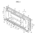
- FIG. 1 is an exploded perspective view of a plasma display device according to a first exemplary embodiment of the present invention.
- the plasma display device includes a plasma display panel (PDP) 11, heat dissipation sheets 13, a chassis base 15 and printed circuit board assemblies (PBAs) 17.
- PDP plasma display panel
- PBAs printed circuit board assemblies
- the PDP 11 includes a front substrate 11a and a rear substrate 11b, and displays an image by utilizing a gas discharge generated between the two substrates 11a and 11b.
- the general constitution and function of the PDP 11 are well known to those of ordinary skill in the art, so a detailed description of its general constituent elements is omitted.
- the first exemplary embodiment of the present invention relates to a plasma display device that determines a touch position by utilizing a change in the amount of emitted infrared rays according to whether a touch is made.
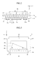
- FIG. 2 is a cross-sectional view taken along the line II-II of FIG. 1 .
- the chassis base 15 is attached to a rear of the PDP 11 using a double-sided adhesive tape 14 to support the PDP 11.
- the heat dissipation sheets 13 are secured between the PDP 11 and the chassis base 15 by the adherence of the double-sided adhesive tape 14.
- the PBAs 17 are mounted on the rear of the chassis base 15 to be connected electrically to the PDP 11.
- the PBAs 17 are on a plurality of bosses 18 on the chassis base 15 and are fixed by the setscrews 19 engaged with the bosses 18.
- the PBAs 17 according to one embodiment include a sustain board 17a that controls the sustain electrodes (not shown), a scan board 17b that controls the scan electrodes (not shown), and an address buffer board 17c that controls the address electrodes (not shown).
- the PBAs 17 include a logic board 17d that receives video signals from an external device and generates control signals for driving the address electrodes, the sustain electrodes and the scan electrodes, and applies the control signals to the corresponding PBAs, respectively, and a power supply board 17e that supplies power for driving the respective PBAs 17a, 17b, 17c, and 17d.
- the PDP 11 of this embodiment displays an image according to the drive of the PBAs 17.
- FIG. 3 is a front view of the PDP 11 of FIG. 1 .
- the PDP 11 includes a display area DA where the image is displayed, and a non-display area ND where the image is not displayed at a periphery of the display area DA.
- the PDP 11 is formed in a quadrangle (e.g., a rectangle shape) so that, in the display area, the PDP 11 has a pair of long sides 111, opposed to each other, and a pair of short sides 211, opposed to each other.
- the short side 211 may extend in a direction crossing to the long sides 111.
- the infrared rays having a substantially uniform dispersion are emitted from the front surface of the display area DA while the image is displayed (see FIG. 2 ). Also, although some infrared rays are emitted from the non-display area ND, the infrared rays emitted from the non-display area ND are not relevant to the present invention so that they will not be discussed.
- the infrared radiation or rays are emitted from the front surface of the display area DA of the PDP 11.
- the PDP shields the infrared rays emitted from the display area DA using an infrared shield filter (not shown).
- the infrared rays emitted from the display area DA are not completely shielded by the infrared shield filter but are about 85% shielded, leaving about 15% of the infrared rays that are transmitted through the infrared shield filter. Therefore, the present exemplary embodiment may be applied even when the infrared shield filter is applied.
- the infrared rays are emitted from the front surface of the display area DA in a substantially uniform dispersion to reflect off a physical solid (an object or a substance) PS positioned in front of the display area DA.
- the amount of infrared rays is changed at the position of the physical solid PS.
- the corresponding touch position of the physical solid PS is determined on the display area DA.
- an infrared sensor e.g., an infrared sensor camera
- an infrared sensor 20 is provided on the PDP 11 in order to detect the change in the amount of infrared rays emitted from the display area DA.
- the infrared sensor camera 20 is provided in front of the PDP 11.
- the infrared sensor camera 20 detects the change in the amount of infrared rays emitted from the front surface of the display area and reflected from the physical solid PS in front of the display area DA.
- the infrared sensor camera 20 continuously detects infrared rays, in order to detect changes (e.g., instantaneous changes) in the amount of infrared rays emitted from the PDP 11.
- infrared rays may be implemented in various forms known to those skilled in the art according to the preferences of individual designers, so a detailed explanation thereof will be omitted.
- the infrared sensor camera 20 is at one side (e.g., attached to a front surface) of the PDP 11.
- a front case and a rear case are provided on the front and the rear of the PDP 11, respectively, so that the infrared sensor camera 20 may also be attached to the front case (not shown). If the infrared sensor camera 20 can detect the change in the amount of infrared rays emitted from the display area DA, the infrared sensor camera 20 may be attached to the PDP 11 or the front case.
- two infrared sensor cameras 20 determine a touch position using two axes that are opposed to each other or intersected with each other.
- the two detecting axes on which the infrared sensor cameras 20 are formed may be opposed to each other on a straight line or be intersected with each other on a plane. A point where the two detecting axes are opposed or intersected corresponds to a touch position.
- the infrared sensor camera 20 includes a first front side infrared sensor camera 21 and a second front side infrared sensor camera 22 that are disposed at the non-display area ND corresponding to opposing ends of quadrangular edges (e.g., corners) of the display area DA.
- the first front side infrared sensor camera 21 and the second front side infrared sensor camera 22 are provided at respective ends of the lower long side 111 of the pair of long sides 111 (e.g., at the lower corners of the display area DA).
- the first and second front side infrared sensors cameras 21 and 22 detect the change in the amount of infrared rays from the display area DA by utilizing a triangulation method from the two ends of the long side 111.
- a first straight line distance L1 between the first front side infrared sensor camera 21 and the second front side infrared sensor camera 22 is measured, a first angle ⁇ of the first front side infrared sensor camera 21 and a second angle ⁇ of the second front side infrared sensor camera 22 are measured with reference to the first straight line distance L1, and the point of intersection of lines representing the respective detection directions is determined to be a touch position.
- the infrared sensor cameras 20 respectively include a lens having a view angle of at least 90°, that is, the detecting range.
- the lens of the sensor camera 20 has the view angle in the range of 90° to 180°, and in some embodiments the lens of the sensor camera 20 has the focal distance in the range of 15mm to 20mm.
- the view angle and the focal distance of the lens in the infrared sensor camera 20 are represented by the following Table 1.
- some embodiments utilize the lens of the infrared sensor camera 20 having a view angle in the range of 94° to 110°.
- the lens of the infrared sensor camera 20 has the focal distance in the range of 16mm to 20mm.
- the first and second front side infrared sensor cameras 21 and 22 that have the lens having the view angle and the focal distance as described above enable the detection of touches over substantially the entire display area DA.
- CMOS complementary metal-oxide semiconductor
- the view angle of 110° in the first and second front side infrared sensor cameras 21 and 22 can prevent the overlapped area from being exceedingly broad, while not omitting portions of the display area DA, compared to the view angle of 180° therein.
- the plasma display device in the first exemplary embodiment includes a controller 30.
- the controller 30 receives detecting signals corresponding to the change in the amount of infrared rays detected and applied by the infrared sensor camera 20, and the position where the change in the amount of infrared rays occurs is determined to be a touch position.
- the controller 30 has built-in (e.g., predetermined) position data for the display area DA and compares the built-in position data with the position data where the change in the amount of the detected infrared rays occurs, making it possible to determine the touch position of the physical solid PS in the display area DA.
- built-in e.g., predetermined
- the controller 30 includes an electric circuit, and may have various different components according to design preferences, so a detailed explanation thereof will be omitted. That is, those skilled in the art would know how to design and build the controller 30 based on the disclosure herein.
- the controller 30 may be provided in or on any one of the printed circuit board assemblies PBA 17. In the first exemplary embodiment, the controller 30 is provided in the logic board 17d.
- the infrared sensor camera 20 continuously detects the infrared rays emitted from the front surface of the display area DA.
- the infrared rays having a substantially uniform dispersion have a change in the amount thereof around the physical solid PS.
- the infrared sensor camera 20 detects the change in the amount of infrared rays.
- the detection signals corresponding to the change in the amount of infrared rays are transmitted to the controller 30 in the logic board 17d.
- the controller 30 compares the built-in position data with the position data detected as having a change in the amount of infrared rays to determine the touch position of the physical solid PS on the display area DA.
- FIG. 4 is an exploded perspective view of a plasma display device according to a second exemplary embodiment of the present invention.
- the infrared sensor camera 20 is provided at the front side of the PDP 11, but in the second exemplary embodiment, the infrared sensor camera 40 is provided at the rear side of the PDP 11.
- the infrared sensor camera 20 detects a change in the amount of infrared rays at the front of the PDP 11, but in the second exemplary embodiment, the infrared sensor camera 40 detects a change in the amount of infrared rays at the rear of the PDP 11.
- the infrared sensor camera 20 and the controller 30 determine the touch position of the physical solid PS by detecting a change in the amount of infrared rays emitted from the front surface of the display area DA, but in the second exemplary embodiment, the infrared sensor camera 40 and the controller 30 determine the touch position of the physical solid PS by detecting a change in the amount of infrared rays reflected from the physical solid PS through the front surface of the display area DA to the back surface thereof to be emitted from the back surface.
- infrared rays are emitted from the rear surface of the display area DA at a substantially uniform dispersion.
- the amount of infrared rays emitted from the rear surface of the display area DA is less than the amount of infrared rays emitted from the front surface, it is similarly emitted having a substantially uniform dispersion.
- the infrared rays are reflected from the physical solid PS in front of the display area DA to the back to be emitted from the rear surface of the display area DA.
- the change in the amount of infrared rays corresponds to the reflected position. If the change in the amount of infrared rays is detected, the corresponding touch position of the physical solid PS can be determined on the display area DA.
- the second exemplary embodiment has a different constitution from the first exemplary embodiment.
- the chassis base 35 is formed differently from the chassis base 15 in the first exemplary embodiment.
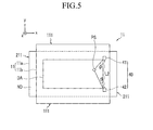
- FIG. 5 is a rear view of the PDP 11 of FIG. 4 .
- the infrared sensor camera 40 is attached to the rear side of the PDP 11.
- the infrared sensor camera 40 can detect the change in the amount of infrared rays in the rear of the display area DA by the infrared rays reflected from the physical solid PS in front of the display area DA to the back surface to be emitted from the back surface, it may be attached to the PDP 11 or the chassis base 35.
- the infrared sensor camera 40 includes two sensors (e.g., two infrared sensor cameras).
- the infrared sensor camera 40 includes a first rear side infrared sensor camera 41 and a second rear side infrared sensor camera 42 that are disposed on the non-display area ND corresponding to the two ends of quadrangular edges of the display area DA (e.g., at opposing corners on the short side of the display area DA), at the rear side of the PDP.
- first rear side infrared sensor camera 41 and the second rear side infrared sensor camera 42 are provided at respective ends of the short side 211 on the right side of the pair of short sides 211 (see FIG. 5 ).
- the first and second rear side infrared sensor cameras 41 and 42 detect the change in the amount of infrared rays in the display area DA by a triangulation method from the two ends of the short side 211.
- a second straight line distance L2 between the first rear side infrared sensor camera 41 and the second rear side infrared sensor camera 42 is measured, a first angle ⁇ of the first rear side infrared sensor camera 41 and a second angle ⁇ of the second rear side infrared sensor camera 42 are measured with reference to the first straight line distance L2, and the point of intersection is determined to correspond to a touch position.
- the chassis base 35 provides a space S for receiving the infrared sensor camera 40 between the PDP 11 and the chassis base 35 and for detecting a change in the amount of infrared rays (see FIG. 7 ).
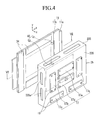
- FIG. 6 is a front perspective view of the chassis base 35 of FIG. 4 .
- the chassis base 35 includes a first horizontal member 135, a second horizontal member 235 and a vertical member 335.
- the planes of the first and second horizontal member 135 and 235 are substantially parallel to the plane of PDP 11, and the vertical member 335 is perpendicular to the plane of the PDP 11.
- the first horizontal member 135 is attached to the PDP 11, facing the pair of long sides 111 and the pair of short sides 211.
- the first horizontal member 135 is formed in a rectangular frame such that it is attached to substantially the entirety of the long sides 111 and the short sides 211.
- the attachment area of the chassis base 35 and the PDP 11 is more limited in the second exemplary embodiment than in the first exemplary embodiment, due to the space S. Under such a limited circumstance, the first horizontal member 135 should have a maximum possible attachment area.
- the double-sided adhesive tape 34 is interposed between the chassis base 35 and the PDP 11 to attach them.
- the double-sided adhesive tape 34 is interposed between the first horizontal member 135 and the pair of long sides 111, opposing to each other, and between the first horizontal member 135 and the pair of short sides 211, opposing to each other, respectively.
- FIG. 7 is a cross-sectional view taken along the line VII-VII of FIG. 4 .
- the second horizontal member 235 provides a mounting space of the printed circuit board assemblies PBA 17, in the same manner as the chassis base 15 in the first exemplary embodiment.
- the vertical member 335 extends (e.g., is bent) from the first horizontal member 135 away from the PDP 11 to connect to the second horizontal member 235.
- chassis base 35 creates a space S between the first horizontal member 135 and the second horizontal member 235 according to the size of the vertical member 335.
- the vertical member 335 includes at least one air vent hole 335a.
- the air vent hole 335a connects the space S between the PDP 11 and the second horizontal member 235 to the outside.
- the air vent hole 335a discharges some of the heat in the space S by turbulent air formed therethrough.
- the infrared sensor cameras 20 and 40 applied to the first and second exemplary embodiments detect the change in the amount of infrared rays emitted from the front surface and the rear surface, respectively, of the display area DA.
- the infrared sensor cameras 20 and 40 may be replaced by other elements.
- FIG. 8 is a rear view of a PDP in a plasma display device according to a third exemplary embodiment of the present invention.
- the infrared sensor cameras 20 and 40 are provided corresponding to both ends of a long side 111 of the PDP 11 (e.g., the corners at the top or the bottom of FIG. 8 ) or corresponding to both ends of a short side 211 thereof (e.g., the corners at the left or right of FIG. 8 ).
- an infrared sensor 50 is disposed in the non-display area ND corresponding to the two ends of the quadrangular edges of the PDP 11, diagonally disposed (e.g., at diagonally opposed corners of the display area DA).
- the infrared sensor camera 50 in the third exemplary embodiment may be disposed at the diagonal corners in front of the PDP 11 (not shown) as in the first exemplary embodiment, and may be disposed at the diagonal corners at the rear of the PDP 11 as in the second exemplary embodiment.
- the third exemplary embodiment shows the structure where the infrared sensor camera 50 is provided at the rear of the PDP 11 as shown in FIG. 8 .
- the infrared sensor cameras 50 are attached to the diagonally opposed corners of the rear side of the PDP 11 to detect the change in the amount of infrared rays at the rear of the display area DA by the infrared rays reflected from the physical solid PS in front of the display area DA to the back surface and emitted from the back surface.
- the infrared sensor camera 50 includes a third infrared sensor camera 51 and a fourth infrared sensor camera 52 that are disposed on the non-display area ND corresponding to two diagonally opposed corners of the display area DA, at the rear side of the PDP 11.
- the third and fourth infrared sensor cameras 51 and 52 detect a change in the amount of infrared rays from the display area DA by a triangulation method from the two diagonally opposed corners.
- a third straight line distance L3 between the third infrared sensor camera 51 and the fourth infrared sensor camera 52 is measured, a first angle ⁇ of the third infrared sensor camera 51 and a second angle ⁇ of the fourth infrared sensor camera 52 are measured with reference to the third straight line distance L3, and the intersected point is determined to correspond to a touch position.
- the infrared sensor camera 40 is installed on the front side or the rear side of the PDP 11 and the lens provided in the infrared sensor 40 camera has a view angle in the range of about 90° to 180° so that the number of the infrared sensor cameras is reduced in implementing the touch panel function using infrared rays, thereby making it possible to reduce costs.
Landscapes
- Engineering & Computer Science (AREA)
- General Engineering & Computer Science (AREA)
- Theoretical Computer Science (AREA)
- Physics & Mathematics (AREA)
- Human Computer Interaction (AREA)
- General Physics & Mathematics (AREA)
- Plasma & Fusion (AREA)
- Devices For Indicating Variable Information By Combining Individual Elements (AREA)
- Photometry And Measurement Of Optical Pulse Characteristics (AREA)
- Control Of Indicators Other Than Cathode Ray Tubes (AREA)
Applications Claiming Priority (1)
| Application Number | Priority Date | Filing Date | Title |
|---|---|---|---|
| KR1020080120662A KR100982331B1 (ko) | 2008-12-01 | 2008-12-01 | 플라즈마 디스플레이 장치 |
Publications (2)
| Publication Number | Publication Date |
|---|---|
| EP2192473A2 true EP2192473A2 (fr) | 2010-06-02 |
| EP2192473A3 EP2192473A3 (fr) | 2010-10-20 |
Family
ID=42062401
Family Applications (1)
| Application Number | Title | Priority Date | Filing Date |
|---|---|---|---|
| EP09177239A Withdrawn EP2192473A3 (fr) | 2008-12-01 | 2009-11-26 | Dispositif d'affichage à plasma |
Country Status (4)
| Country | Link |
|---|---|
| US (1) | US8558816B2 (fr) |
| EP (1) | EP2192473A3 (fr) |
| KR (1) | KR100982331B1 (fr) |
| CN (1) | CN101751825B (fr) |
Cited By (2)
| Publication number | Priority date | Publication date | Assignee | Title |
|---|---|---|---|---|
| CN104486543A (zh) * | 2014-12-09 | 2015-04-01 | 北京时代沃林科技发展有限公司 | 智能终端触控方式控制云台摄像头的设备和方法 |
| CN109634429A (zh) * | 2018-12-29 | 2019-04-16 | 联想(北京)有限公司 | 一种电子设备及信息获取方法 |
Families Citing this family (5)
| Publication number | Priority date | Publication date | Assignee | Title |
|---|---|---|---|---|
| TW201133309A (en) * | 2010-03-24 | 2011-10-01 | Zhi-Xuan Liao | Apparatus and method of combining optical image and touch panel to uni-axially interpreting position of object to be measured |
| US8883024B2 (en) | 2010-10-18 | 2014-11-11 | Tokyo Electron Limited | Using vacuum ultra-violet (VUV) data in radio frequency (RF) sources |
| TWI470510B (zh) * | 2012-04-19 | 2015-01-21 | Wistron Corp | 光學觸控裝置及觸控感測方法 |
| KR101973168B1 (ko) * | 2012-08-24 | 2019-04-29 | 삼성디스플레이 주식회사 | 멀티 터치 및 터치 힘을 인식하는 터치 표시장치 및 그 구동 방법 |
| CN105138193A (zh) * | 2015-09-09 | 2015-12-09 | 宁波舜宇光电信息有限公司 | 用于光学触摸屏的摄像模组及其镜头 |
Citations (3)
| Publication number | Priority date | Publication date | Assignee | Title |
|---|---|---|---|---|
| US3775560A (en) | 1972-02-28 | 1973-11-27 | Univ Illinois | Infrared light beam x-y position encoder for display devices |
| EP1780697A2 (fr) | 2005-10-28 | 2007-05-02 | LG Electronics Inc. | Appareil d'affichage à plasma équipé d'un capteur de lumière ambiante ou d'un capteur de mouvement |
| EP2093652A2 (fr) | 2008-02-25 | 2009-08-26 | Samsung SDI Co., Ltd. | Dispositif d'affichage à plasma |
Family Cites Families (39)
| Publication number | Priority date | Publication date | Assignee | Title |
|---|---|---|---|---|
| US4782328A (en) | 1986-10-02 | 1988-11-01 | Product Development Services, Incorporated | Ambient-light-responsive touch screen data input method and system |
| JPH05160702A (ja) | 1991-12-06 | 1993-06-25 | Fujitsu Ltd | 赤外線タッチセンサ |
| US5660471A (en) * | 1993-02-26 | 1997-08-26 | Matsushita Electric Industrial Co., Ltd. | Temperature distribution measuring device and measuring method |
| JP3305544B2 (ja) | 1995-09-20 | 2002-07-22 | 株式会社富士通ゼネラル | タッチパネル付プラズマディスプレイ |
| JPH09171173A (ja) | 1995-12-20 | 1997-06-30 | Hitachi Ltd | 液晶パネルの防塵装置 |
| CN1721891A (zh) | 1998-01-28 | 2006-01-18 | 美国3M公司 | 红外线干涉滤光器 |
| US20030214498A1 (en) * | 1998-04-30 | 2003-11-20 | David Gothard | High resolution computer operated digital display system |
| JP4033582B2 (ja) * | 1998-06-09 | 2008-01-16 | 株式会社リコー | 座標入力/検出装置および電子黒板システム |
| JP2000010493A (ja) | 1998-06-22 | 2000-01-14 | Matsushita Electric Ind Co Ltd | 映像表示装置 |
| JP3898357B2 (ja) | 1998-09-28 | 2007-03-28 | 日東電工株式会社 | プラズマディスプレイパネル用フィルター |
| JP4094794B2 (ja) | 1999-09-10 | 2008-06-04 | 株式会社リコー | 座標検出装置、情報記憶媒体および座標検出方法 |
| JP2001084058A (ja) | 1999-09-14 | 2001-03-30 | Ricoh Co Ltd | 情報入力・検出・表示装置 |
| JP2001175416A (ja) | 1999-12-16 | 2001-06-29 | Pioneer Electronic Corp | 座標位置検知方法およびこれを用いた表示装置 |
| US6690363B2 (en) * | 2000-06-19 | 2004-02-10 | Next Holdings Limited | Touch panel display system |
| JP4538933B2 (ja) | 2000-10-06 | 2010-09-08 | 三菱電機株式会社 | 位置検出機能つき液晶表示装置 |
| JP2003099205A (ja) | 2001-09-21 | 2003-04-04 | Ricoh Co Ltd | 表示一体型座標入力装置 |
| US6954197B2 (en) * | 2002-11-15 | 2005-10-11 | Smart Technologies Inc. | Size/scale and orientation determination of a pointer in a camera-based touch system |
| US6972401B2 (en) * | 2003-01-30 | 2005-12-06 | Smart Technologies Inc. | Illuminated bezel and touch system incorporating the same |
| JP4277615B2 (ja) | 2003-08-01 | 2009-06-10 | パナソニック電工株式会社 | 近赤外線吸収組成物及び近赤外線吸収フィルター |
| JP4125200B2 (ja) * | 2003-08-04 | 2008-07-30 | キヤノン株式会社 | 座標入力装置 |
| JP4413065B2 (ja) * | 2004-01-28 | 2010-02-10 | 健爾 西 | 画像表示装置および画像表示システム |
| KR20070020431A (ko) * | 2004-02-24 | 2007-02-21 | 뉴라이트 코포레이션 | 평판 디스플레이용의 펜라이트 및 터치 스크린 데이터 입력시스템과 그 방법 |
| JP4649933B2 (ja) | 2004-09-30 | 2011-03-16 | マツダ株式会社 | 車両用情報表示装置 |
| KR100626063B1 (ko) | 2005-03-18 | 2006-09-22 | 삼성에스디아이 주식회사 | 터치 스크린형 플라즈마 디스플레이 장치 |
| JP4455392B2 (ja) * | 2005-04-15 | 2010-04-21 | キヤノン株式会社 | 座標入力装置及びその制御方法、プログラム |
| US9019209B2 (en) | 2005-06-08 | 2015-04-28 | 3M Innovative Properties Company | Touch location determination involving multiple touch location processes |
| KR20070024969A (ko) | 2005-08-31 | 2007-03-08 | (주)제니텀 엔터테인먼트 컴퓨팅 | 적외선 감지 사용자 인터페이스를 갖는 벽면형 디스플레이장치 및 그 동작 방법 |
| KR100829172B1 (ko) | 2006-02-20 | 2008-05-13 | 호감테크놀로지(주) | 적외선 터치스크린 장치 및 적외선 터치스크린의 터치점의좌표 산출 방법 |
| JP4541438B2 (ja) | 2006-03-27 | 2010-09-08 | パイオニア株式会社 | 情報コードの読取装置及び読取方法 |
| US8203445B2 (en) * | 2006-03-28 | 2012-06-19 | Wireless Environment, Llc | Wireless lighting |
| JP2007271773A (ja) | 2006-03-30 | 2007-10-18 | Fujitsu Hitachi Plasma Display Ltd | プラズマディスプレイ装置 |
| JP2007288354A (ja) * | 2006-04-13 | 2007-11-01 | Opt Kk | カメラ装置、画像処理装置および画像処理方法 |
| JP4805022B2 (ja) | 2006-05-25 | 2011-11-02 | シャープ株式会社 | 表示装置、端末装置、画像貼付システムおよびそれらの方法 |
| EP2135155B1 (fr) * | 2007-04-11 | 2013-09-18 | Next Holdings, Inc. | Système à écran tactile avec procédés de saisie par effleurement et clic |
| JP4891179B2 (ja) * | 2007-08-13 | 2012-03-07 | キヤノン株式会社 | 座標入力装置、座標入力方法 |
| JP2009063941A (ja) * | 2007-09-10 | 2009-03-26 | Sumitomo Electric Ind Ltd | 遠赤外線カメラ用レンズ、レンズユニット及び撮像装置 |
| KR100804815B1 (ko) * | 2007-09-10 | 2008-02-20 | (주)컴버스테크 | 외란광에 강한 적외선 카메라를 이용한 터치스크린 |
| CN101127175A (zh) | 2007-10-10 | 2008-02-20 | 北京诚意创科软件开发有限公司 | 教室用大屏幕等离子显示器 |
| KR101016676B1 (ko) * | 2008-12-01 | 2011-02-25 | 삼성에스디아이 주식회사 | 플라즈마 표시 장치 및 그 구동 방법 |
-
2008
- 2008-12-01 KR KR1020080120662A patent/KR100982331B1/ko not_active Expired - Fee Related
-
2009
- 2009-11-20 US US12/622,846 patent/US8558816B2/en not_active Expired - Fee Related
- 2009-11-26 EP EP09177239A patent/EP2192473A3/fr not_active Withdrawn
- 2009-12-01 CN CN2009102466876A patent/CN101751825B/zh not_active Expired - Fee Related
Patent Citations (3)
| Publication number | Priority date | Publication date | Assignee | Title |
|---|---|---|---|---|
| US3775560A (en) | 1972-02-28 | 1973-11-27 | Univ Illinois | Infrared light beam x-y position encoder for display devices |
| EP1780697A2 (fr) | 2005-10-28 | 2007-05-02 | LG Electronics Inc. | Appareil d'affichage à plasma équipé d'un capteur de lumière ambiante ou d'un capteur de mouvement |
| EP2093652A2 (fr) | 2008-02-25 | 2009-08-26 | Samsung SDI Co., Ltd. | Dispositif d'affichage à plasma |
Cited By (3)
| Publication number | Priority date | Publication date | Assignee | Title |
|---|---|---|---|---|
| CN104486543A (zh) * | 2014-12-09 | 2015-04-01 | 北京时代沃林科技发展有限公司 | 智能终端触控方式控制云台摄像头的设备和方法 |
| CN104486543B (zh) * | 2014-12-09 | 2020-11-27 | 北京时代沃林科技发展有限公司 | 智能终端触控方式控制云台摄像头的系统 |
| CN109634429A (zh) * | 2018-12-29 | 2019-04-16 | 联想(北京)有限公司 | 一种电子设备及信息获取方法 |
Also Published As
| Publication number | Publication date |
|---|---|
| US20100134445A1 (en) | 2010-06-03 |
| CN101751825B (zh) | 2012-11-14 |
| EP2192473A3 (fr) | 2010-10-20 |
| KR20100062196A (ko) | 2010-06-10 |
| KR100982331B1 (ko) | 2010-09-15 |
| CN101751825A (zh) | 2010-06-23 |
| US8558816B2 (en) | 2013-10-15 |
Similar Documents
| Publication | Publication Date | Title |
|---|---|---|
| EP2192473A2 (fr) | Dispositif d'affichage à plasma | |
| US8508488B2 (en) | Display apparatus having touch screen function | |
| US8093810B2 (en) | Plasma display device | |
| CN106920478B (zh) | 显示设备 | |
| JP6807867B2 (ja) | ディスプレイのためのセンサデバイス | |
| US10156641B2 (en) | Radiation image sensing apparatus and radiation image sensing system | |
| US20100026645A1 (en) | Touch display panel | |
| US20110063532A1 (en) | Image display device | |
| KR20090092878A (ko) | 적외선 터치스크린 | |
| US7492099B2 (en) | Plasma display device | |
| CN107506096A (zh) | 红外触摸屏框架及其触摸屏 | |
| CN100501517C (zh) | 背光组件及具有该组件的显示装置 | |
| KR20100069505A (ko) | 터치 스크린의 기능을 갖는 표시장치 | |
| US20110032690A1 (en) | Display apparatus for preventing electromagnetic interference (emi) | |
| CN117316058A (zh) | Led灯板及led显示屏 | |
| CN223859591U (zh) | 一种触控式led一体机 | |
| KR20060086712A (ko) | 직부착 필터 얼라인 마크가 형성된 디스플레이 패널 모듈 | |
| KR20090016972A (ko) | 플라즈마 디스플레이 장치 | |
| KR20080042282A (ko) | 플라즈마 디스플레이 장치 | |
| KR100481223B1 (ko) | 표시 패널 세트 및 그 제어 방법 | |
| EP1845550A1 (fr) | Ensemble de filtre et dispositif d'affichage plasma l'utilisant | |
| EP2312565A2 (fr) | Appareil d'affichage à plasma | |
| KR20100119028A (ko) | 디스플레이 장치 | |
| CN105843458A (zh) | 一种l形反射式触控模组 | |
| JP2009258549A (ja) | 画像表示装置及びその制御方法 |
Legal Events
| Date | Code | Title | Description |
|---|---|---|---|
| PUAI | Public reference made under article 153(3) epc to a published international application that has entered the european phase |
Free format text: ORIGINAL CODE: 0009012 |
|
| 17P | Request for examination filed |
Effective date: 20091126 |
|
| AK | Designated contracting states |
Kind code of ref document: A2 Designated state(s): AT BE BG CH CY CZ DE DK EE ES FI FR GB GR HR HU IE IS IT LI LT LU LV MC MK MT NL NO PL PT RO SE SI SK SM TR |
|
| AX | Request for extension of the european patent |
Extension state: AL BA RS |
|
| PUAL | Search report despatched |
Free format text: ORIGINAL CODE: 0009013 |
|
| AK | Designated contracting states |
Kind code of ref document: A3 Designated state(s): AT BE BG CH CY CZ DE DK EE ES FI FR GB GR HR HU IE IS IT LI LT LU LV MC MK MT NL NO PL PT RO SE SI SK SM TR |
|
| AX | Request for extension of the european patent |
Extension state: AL BA RS |
|
| 17Q | First examination report despatched |
Effective date: 20130521 |
|
| STAA | Information on the status of an ep patent application or granted ep patent |
Free format text: STATUS: THE APPLICATION HAS BEEN WITHDRAWN |
|
| 18W | Application withdrawn |
Effective date: 20131127 |