EP2192586A1 - Système de traitement de signal et support de stockage d'informations - Google Patents
Système de traitement de signal et support de stockage d'informations Download PDFInfo
- Publication number
- EP2192586A1 EP2192586A1 EP09172770A EP09172770A EP2192586A1 EP 2192586 A1 EP2192586 A1 EP 2192586A1 EP 09172770 A EP09172770 A EP 09172770A EP 09172770 A EP09172770 A EP 09172770A EP 2192586 A1 EP2192586 A1 EP 2192586A1
- Authority
- EP
- European Patent Office
- Prior art keywords
- information
- sub
- signal
- modulator
- module
- Prior art date
- Legal status (The legal status is an assumption and is not a legal conclusion. Google has not performed a legal analysis and makes no representation as to the accuracy of the status listed.)
- Granted
Links
- 238000003860 storage Methods 0.000 title claims abstract description 16
- 238000012545 processing Methods 0.000 title claims description 10
- 230000005540 biological transmission Effects 0.000 claims abstract description 50
- 230000010365 information processing Effects 0.000 claims description 5
- 238000000034 method Methods 0.000 description 83
- 230000008569 process Effects 0.000 description 44
- 230000010354 integration Effects 0.000 description 34
- 238000001514 detection method Methods 0.000 description 18
- 230000000694 effects Effects 0.000 description 9
- 238000012937 correction Methods 0.000 description 8
- 238000010586 diagram Methods 0.000 description 6
- 238000009826 distribution Methods 0.000 description 6
- 238000004891 communication Methods 0.000 description 5
- 238000001914 filtration Methods 0.000 description 5
- 238000004519 manufacturing process Methods 0.000 description 5
- 230000003287 optical effect Effects 0.000 description 5
- 238000012935 Averaging Methods 0.000 description 4
- 238000005070 sampling Methods 0.000 description 4
- 230000008054 signal transmission Effects 0.000 description 4
- 230000006872 improvement Effects 0.000 description 3
- 230000001629 suppression Effects 0.000 description 3
- 230000002087 whitening effect Effects 0.000 description 3
- 230000002411 adverse Effects 0.000 description 2
- 230000003247 decreasing effect Effects 0.000 description 2
- 230000009467 reduction Effects 0.000 description 2
- 230000008901 benefit Effects 0.000 description 1
- 125000004122 cyclic group Chemical group 0.000 description 1
- 230000007423 decrease Effects 0.000 description 1
- 230000002708 enhancing effect Effects 0.000 description 1
- 238000011156 evaluation Methods 0.000 description 1
- 230000000670 limiting effect Effects 0.000 description 1
- 238000012986 modification Methods 0.000 description 1
- 230000004048 modification Effects 0.000 description 1
- 230000036961 partial effect Effects 0.000 description 1
- 230000002829 reductive effect Effects 0.000 description 1
- 238000006467 substitution reaction Methods 0.000 description 1
Images


Classifications
-
- G—PHYSICS
- G11—INFORMATION STORAGE
- G11B—INFORMATION STORAGE BASED ON RELATIVE MOVEMENT BETWEEN RECORD CARRIER AND TRANSDUCER
- G11B20/00—Signal processing not specific to the method of recording or reproducing; Circuits therefor
- G11B20/10—Digital recording or reproducing
- G11B20/14—Digital recording or reproducing using self-clocking codes
-
- G—PHYSICS
- G11—INFORMATION STORAGE
- G11B—INFORMATION STORAGE BASED ON RELATIVE MOVEMENT BETWEEN RECORD CARRIER AND TRANSDUCER
- G11B20/00—Signal processing not specific to the method of recording or reproducing; Circuits therefor
- G11B20/00086—Circuits for prevention of unauthorised reproduction or copying, e.g. piracy
- G11B20/0021—Circuits for prevention of unauthorised reproduction or copying, e.g. piracy involving encryption or decryption of contents recorded on or reproduced from a record carrier
-
- G—PHYSICS
- G11—INFORMATION STORAGE
- G11B—INFORMATION STORAGE BASED ON RELATIVE MOVEMENT BETWEEN RECORD CARRIER AND TRANSDUCER
- G11B20/00—Signal processing not specific to the method of recording or reproducing; Circuits therefor
- G11B20/00086—Circuits for prevention of unauthorised reproduction or copying, e.g. piracy
- G11B20/00572—Circuits for prevention of unauthorised reproduction or copying, e.g. piracy involving measures which change the format of the recording medium
- G11B20/00579—Circuits for prevention of unauthorised reproduction or copying, e.g. piracy involving measures which change the format of the recording medium said format change concerning the data encoding, e.g., modulation schemes violating run-length constraints, causing excessive DC content, or involving uncommon codewords or sync patterns
-
- G—PHYSICS
- G11—INFORMATION STORAGE
- G11B—INFORMATION STORAGE BASED ON RELATIVE MOVEMENT BETWEEN RECORD CARRIER AND TRANSDUCER
- G11B20/00—Signal processing not specific to the method of recording or reproducing; Circuits therefor
- G11B20/00086—Circuits for prevention of unauthorised reproduction or copying, e.g. piracy
- G11B20/00884—Circuits for prevention of unauthorised reproduction or copying, e.g. piracy involving a watermark, i.e. a barely perceptible transformation of the original data which can nevertheless be recognised by an algorithm
-
- G—PHYSICS
- G11—INFORMATION STORAGE
- G11B—INFORMATION STORAGE BASED ON RELATIVE MOVEMENT BETWEEN RECORD CARRIER AND TRANSDUCER
- G11B20/00—Signal processing not specific to the method of recording or reproducing; Circuits therefor
- G11B20/10—Digital recording or reproducing
- G11B20/14—Digital recording or reproducing using self-clocking codes
- G11B20/1403—Digital recording or reproducing using self-clocking codes characterised by the use of two levels
- G11B20/1423—Code representation depending on subsequent bits, e.g. delay modulation, double density code, Miller code
- G11B20/1426—Code representation depending on subsequent bits, e.g. delay modulation, double density code, Miller code conversion to or from block codes or representations thereof
- G11B2020/1457—Code representation depending on subsequent bits, e.g. delay modulation, double density code, Miller code conversion to or from block codes or representations thereof wherein DC control is performed by calculating a digital sum value [DSV]
Definitions
- One embodiment of the invention relates to an information recording/reproducing system which records sub-information by superimposing the sub-information on main information, an information transmission system which transmits sub-information by superimposing the sub-information on main information, and an information storage medium.
- secret information on which confidentiality is required for copyright protection, is recorded by a physical modulation method that is different from the modulation method of main information, thereby making difficult reproduction and duplication of the secret information.
- sub-information is substituted for and embedded in main information in the process of encoding (the encoding including error correction encoding and code modulation).
- the secret information modulation/recording method employs different modulation methods for the main information and the secret information in the information encoding process. Thereby, in an apparatus having only a main information reproduction system, the reproduction of secret information is disabled, and no trace of secret information remains in the processed result of the main information reproduction system.
- the structure of the combination between an ordinary optical disc drive and a personal computer which is connected to this optical disc drive there is an advantage that no secret information is included in data bits that are read out from the personal computer, whereby bit-by-bit copy (copy in units of a bit) can be prevented.
- a secret information recording system is provided to only an authorized specific disc manufacturer.
- a secret information reproducing system is provided to only an authorized specific reproducing apparatus manufacturer.
- the secret information recording/reproducing system can be disclosed to the limited, necessary range.
- the secret information recording/reproducing system is disclosed to only reliable manufacturers through examinations and contracts. Thus, this also serves to prevent the manufacture of illegal discs and the manufacture of illegal reproducing apparatuses by illegal manufacturers.
- the superimposition of sub-information on main information means that the presence of the sub-information is a disturbance to the main information.
- the level of the sub-information be lowered to such a level that the sub-information be fully reproduced and that the reproduction of the main information may not be affected by the sub-information.
- the secret information recording/reproducing system may be decoded when a code analysis is executed by a professional.
- the professional in this context, refers to, for example, an illegal disc manufacturer having manufacturing equipment and expertise which are equivalent to those of an authorized optical disc manufacturer.
- An object of the invention is to provide a system which transmits or records information with sub-information being superimposed on main information, suppresses an effect (recording/reproduction quality, transmission quality, recording/reproduction performance, transmission performance, etc.) of superimposing the sub-information for a transmission or recording of the main information, and ensures a recording/reproduction performance and transmission performance of the sub-information.
- Another object of the invention is to provide a system which transmits or records information with sub-information being superimposed on main information, and in which it is difficult to recognize the presence of the sub-information which is used to a copyright protection in order to prevent an illegal copy of the information and easy recognition of the sub-information.
- a signal processing system which superimposes a sub-information signal on a main information signal for transmission or recording, the system comprising a first encoder configured to encode main information; a second encoder configured to encode sub-information; a first modulator configured to modulate a carrier based on an output of the first encoder; a duplicating module configured to duplicate an output of the second encoder to generate encoded sub-information units; and a second modulator configured to amplitude-modulate an output of the first modulator based on the encoded sub-information units, wherein the second modulator is configured to amplitude-modulate with ⁇ /( ⁇ (2 N ) 1/2 ) being 0.4 or less, wherein a noise power of a transmission path or a storage medium is ⁇ 2 , a number of the encoded sub-information units is N, signal levels after amplitude modulation, which correspond to bit 1 and bit 0
- FIG. 1 shows the basic structure of an information recording/reproducing/transmission system according to a first embodiment of the present invention.
- Main information 10 is encoded by an encoding module 12.
- the encoding module 12 executes error correction encoding, modulation encoding aiming at, e.g. band restriction corresponding to a storage medium or a communication path, and sync code addition.
- Encoded data which is output from the encoding module 12, is supplied to a signal modulating module 14.
- the signal modulating module 14 modulates a carrier signal (not shown) on the basis of the encoded data of the main information, and outputs a recording signal which is to be recorded on a medium, or a transmission signal which is to be transmitted to a communication path.
- signal modulation methods for instance, amplitude modulation, frequency modulation, phase modulation, and combinations thereof.
- the present invention does not depend on the signal modulation method.
- Sub-information 20 is encoded by an encoding module 22.
- the encoding module 22 executes a process similar to the process that is executed by the encoding module 12.
- Encoded data which is output from the encoding module 22, is supplied to a code duplicating/shuffling/scrambling module 24.
- the code duplicating/shuffling/scrambling module 24 duplicates and multiplexes the encoded data of the sub-information in a predetermined unit of data so that an integration process can be executed at a time of reproduction.
- the code duplicating/shuffling/scrambling module 24 executes a shuffling process for shuffling the order of data between the predetermined units of duplicated data.
- the unit of shuffling may be a bit unit or a code unit, or the unit of shuffling may span a plurality of units of data. From the standpoint of confidentiality, it is desirable to execute shuffling with a finer unit. Instead of shuffling, or in addition to shuffling, scrambling may be executed. Thereby, the confidentiality is further enhanced.
- a scramble sequence used for scrambling may be successively generated by using specific information as a seed, or a predetermined pattern may be used.
- specific information use may be made of secret information, such as a disc unique ID, a separately transmitted ID, or a secret key.
- secret information such as a disc unique ID, a separately transmitted ID, or a secret key.
- the confidentiality of sub-information is further enhanced.
- As a pattern generating method use may be made of a method using an M-sequential random number. Further, if a firmer random number sequence is desired, use may be made of a sequence using firm block ciphers such as AES.
- the output of the signal modulating module 14 and the output of the code duplicating/shuffling/scrambling module 24 are supplied to a signal modulating module 16.
- the signal modulating module 16 like the signal modulating module 14, modulates the output of the signal modulating module 14 on the basis of the output of the code duplicating/shuffling/scrambling module 24.
- the modulated signal of the main information and the modulated signal of the sub-information are, in a superimposed state, recorded/reproduced in/from the storage medium, or transmitted via the transmission medium.
- the superimposition of signals depends on the modulation methods of the signal modulating module 14 and 16. For example, when the main information is amplitude-modulated and the sub-information is frequency-modulated, the signal superimposition is executed by frequency-modulating the frequency of the modulated signal of the main information on the basis of the modulated signal of the sub-information. For the frequency modulation, use may be made of an ordinary frequency modulator utilizing PLL. When both main information and sub-information are amplitude-modulated, the signal superimposition can be executed by an adder or a multiplier.
- the sub-information signal be minute and reproducible by integration, that the information amount of the sub-information signal be smaller than the information amount of the main information signal, that a frequency band, in which a high recording efficiency and a high transmission efficiency can be expected, be allocated to the main information signal, and that the main information signal component be sufficiently suppressed by the filtering in discrimination of the sub-information signal. Therefore, it is desirable that the frequency band of the sub-information signal be sufficiently lower than the frequency band of the main information signal.
- the central frequency in the recording/reproducing/transmission frequency band of the main information signal is F main
- the central frequency r sub in the recording/reproducing/transmission frequency band of the sub-information signal is F sub ⁇ F main /100.
- the sub-information may be superimposed over the entirety of the main information signal, or may be imposed on only a part of the main information signal.
- the main information reproduction module 28 executes a bit discriminating/demodulating/decoding process, and reproduces main information 30.
- the bit discrimination process is a process of executing predetermined filtering, phase synchronization and wave detection, in accordance with the signal modulation method and the characteristics of the storage medium/communication path.
- the sub-information signal detecting module 32 executes a synchronization process in a predetermined signal unit corresponding to the signal modulation method of the sub-information.
- a sync signal use may be made of a sync signal in the main information.
- this sync signal may be used.
- a filtering process, a phase synchronization process or a wave detection process is chosen in accordance with the sub-information signal modulation method and the characteristics of the communication path.
- the sub-information signal, which has been subjected to the synchronization process, is rearranged in the original data order by a deshuffling/descrambling module 34.
- signal integration is executed in units of duplicated data by a signal integrating module 36, whereby the effect of signal component emphasis of the sub-information signal and the effect of noise suppression can be obtained.
- an averaging process for limiting arithmetic bit digits may be executed.
- the output of the signal integrating module 36 which has been adequately emphasized for bit discrimination, is processed by a bit discriminating module 38 and a demodulating and decoding module 40, and sub-information 42 is reproduced.
- FIG. 2 shows an example of the encoding module 12 (or 22).
- An address (packet) information adding module 52 adds address information to the main information 10 or sub-information 20 (pre-encoding data).
- a correction code adding module 54 adds correction codes to the main information 10 or sub-information 20, and a code modulating module 56 modulates/encodes the resultant information.
- a sync signal adding module 58 adds a sync signal to the output of the code modulating module 56, and modulated/encoded data is generated.
- FIG. 3 to FIG. 6 show examples of the specific structure of the part of the signal modulating modules 14 and 16.
- FIG. 3 shows an example in which the modulation methods of both main information and sub-information are amplitude modulation (AM).
- a carrier signal is supplied to an AM modulating module 62, and an output signal of the AM modulating module 62 is supplied to an AM modulating module 64.
- Encoded main information data from the encoding module 12 is supplied to the AM modulating module 62, and the carrier signal is amplitude-modulated by the encoded main information data.
- Encoded sub-information data from the encoding module 22 is supplied to the AM modulating module 64.
- the carrier signal which has been amplitude-modulated by the encoded main information data in the AM modulating module 62, is further amplitude-modulated by the encoded sub-information data. Thereby, the modulated signal of the main information and the modulated signal of the sub-information are superimposed.
- FIG. 4 shows an example in which the modulation method of main information is amplitude modulation, and the modulation method of sub-information is frequency modulation (FM).
- a carrier signal is supplied to an AM modulating module 66, and an output signal of the AM modulating module 66 is supplied to an FM modulating module 68.
- Encoded main information data from the encoding module 12 is supplied to the AM modulating module 66, and the carrier signal is amplitude-modulated by the encoded main information data.
- Encoded sub-information data from the encoding module 22 is supplied to the FM modulating module 68.
- the carrier signal which has been amplitude-modulated by the encoded main information data in the AM modulating module 66, is frequency-modulated by the encoded sub-information data. Thereby, the modulated signal of the main information and the modulated signal of the sub-information are superimposed.
- FIG. 5 shows an example in which the modulation method of main information is amplitude modulation, and the modulation method of sub-information is phase modulation (PM).
- a carrier signal is supplied to an AM modulating module 70, and an output signal of the AM modulating module 70 is supplied to a PM modulating module 72.
- Encoded main information data from the encoding module 12 is supplied to the AM modulating module 70, and the carrier signal is amplitude-modulated by the encoded main information data.
- Encoded sub-information data from the encoding module 22 is supplied to the PM modulating module 72.
- the carrier signal which has been amplitude-modulated by the encoded main information data in the AM modulating module 70, is phase-modulated by the encoded sub-information data. Thereby, the modulated signal of the main information and the modulated signal of the sub-information are superimposed.
- FIG. 6 shows an example in which the modulation method of main information is pulse modulation (e.g. pulse width modulation, pulse amplitude modulation), and the modulation method of sub-information is amplitude modulation.
- a carrier signal is supplied to a pulse modulating module 74, and an output signal of the pulse modulating module 74 is supplied to an AM modulating module 76.
- Encoded main information data from the encoding module 12 is supplied to the pulse modulating module 74, and the carrier signal is subjected to pulse modulation, such as pulse width modulation or pulse number modulation, by the encoded main information data.
- Encoded sub-information data from the encoding module 22 is supplied to the AM modulating module 76.
- the carrier signal which has been pulse-modulated by the encoded main information data in the pulse modulating module 74, is amplitude-modulated by the encoded sub-information data. Thereby, the modulated signal of the main information and the modulated signal of the sub-information are superimposed.
- FIG. 7 shows an example of encoding of sub-information.
- An error correction code (“Secondary Data Parity") according to a predetermined method is generated and added to sub-information, and thus a sub-information data block (“Secondary Data Block”) is composed.
- the error correction code use is made of an arbitrary code such as a general cyclic code or a block code.
- the code after error coding may further be subjected to a predetermined code modulation process for band or pattern restriction.
- use is made of an arbitrary method such as a modulation method for replacing a bit sequence of an arbitrary length with a different sequence according to a predetermined table.
- a code modulation method with a DC suppression effect is desirable.
- Examples of such a code modulation method include a modulation system including a DSV (Digital Sum Value) control bit of a code, and a Bi-phase modulation system.
- a sync signal when included in sub-information, a pattern for synchronization may be embedded in a predetermined unit of a sub-information data block.
- an integration process has an effect of improving a signal-to-noise ratio (S/N). For example, if a noise characteristic is white, an improvement effect of 3log 2 (N) dB is expectable by an N-number of times of integration. Specifically, even if a sub-information signal is minute and an S/N ratio to noise in a communication path or to noise due to a main information signal is 0 dB, the S/N ratio can be improved up to 15 dB by 32-times integration.
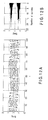
- FIGS. 10A to 10E show improvements of the S/N ratio by integration.
- FIG. 10A shows raw data
- FIG. 12A shows a sub-information signal waveform after integration
- FIG. 12B shows a distribution thereof.
- determination is executed by binarization with a threshold set at 0 level. It is indicated that the detection ratio is higher as the separability of distributions centering on -1 and 1 is higher.
- FIG. 13 shows a method of evaluating a detection signal of sub-information based on the above principle.
- FIG. 13 is a graph plotting absolute values of signals, when the center (threshold value) of two distributions corresponding to code polarities is set at 0.
- values having correlation to the detection ratio of the code polarities can be calculated by a distance ⁇ from the center of the distribution to the threshold value and a standard deviation ⁇ of the distribution.
- the ⁇ value corresponds to the modulation signal amount of sub-information.
- ⁇ and ⁇ is advantageous as a method of determining the signal detection ratio of sub-information, the confidentiality and the reduction of influence on main information.
- the means for evaluating the detection ratio there is a method using ⁇ / ⁇ or an error function, and the upper limit thereof is specified.
- the means for evaluating the confidentiality and the degree of influence on the main information the upper limit of the ⁇ value is specified.
- the lower limits of the ⁇ / ⁇ and ⁇ may be specified.
- the sub-information, after code duplicating, is shuffled.
- the shuffling is a factor of disturbance in the reproduction of sub-information, but the shuffling is effective in whitening noise due to the main information or noise in the information storage medium or transmission path.
- the main information or noise has properties which are characteristic of the frequency band that adversely affects the sub-information signal, it is thought that the noise cannot sufficiently be suppressed by the integration and, as a result, an adequate improvement in signal-to-noise ratio cannot be expected.
- most of frequency bands, which can secure quality are allocated to the recording/reproduction and transmission of main information.
- a method using an M-sequence random number may be used. If a firmer random number sequence is desirable, use may be made of a sequence which utilizes firm block ciphers such as AES. In the case of the successive generation in combination with specific information, secret information, such as a disc unique ID, a separately transmitted ID or a secret key, may be used as the specific information. When the specific information is kept secret by other means, the confidentiality of sub-information is further enhanced.
- unit #0 to unit #N-1 indicate an N-number of duplications of sub-information
- a sub-information data unit (“Secondary Data Unit") indicates sub-information after shuffling.
- the N-number of duplication unit #0 to duplication unit #N-1 are composed of (m+n) byte information B.
- Shuffling is executed by assigning any one of the bytes D 1 to D m+n-1 of sub-information to the byte information B.
- Fig. 9 shows an example of hardware which executes shuffling.
- Sub-information is supplied to a shuffling module 78, and an output of a shuffle pattern generating module 80 is supplied to the shuffling module 78.
- An initial value or a seed (hereinafter referred to as "seed") is supplied to the shuffle pattern generating module 80, a random number corresponding to the initial value is generated, and a shuffle pattern corresponding to the random number is supplied to the shuffling module 78.
- the shuffling module 78 shuffles the sub-information according to the shuffle pattern.
- the seed use may be made of secret information, such as a disc unique ID, a separately transmitted ID or a secret key.
- the seed may be changed each time, or a single seed may always be used.
- a filter band pass filter
- a deshuffling module 86 executes a deshuffling process according to a shuffle pattern which is separately generated by a shuffle pattern generating module 90.
- an integrating/averaging module 88 executes an integration process in units of the same data. In this case, in addition to the integration process, an averaging process for arithmetic bit digit restriction may be executed.
- the signal, after the integration, is input to a rear-stage bit discrimination process.
- a descrambling process is also executed after the deshuffling process.
- the reproduction of the sub-information can be disabled without an integration process on the demodulation side. Further, by changing the integration order by shuffling, the reproduction of sub-information can be made difficult in an illegal apparatus in which the details of both the integration and shuffling are not recognized.
- the single data unit of encoded sub-information is M bytes and the unit of shuffling is 1 byte
- the number of patterns of shuffling is a factorial M! of M.
- the number of all shuffling patterns is M! ⁇ N.
- FIG. 15 shows a transmission-side signal processing unit.
- Sub-information 20 is encoded by the encoding module 22, and a signal duplicating module 104 generates an N-number of duplications 106 (unit #0 to unit #N-1) each composed of a predetermined data unit.
- each unit may comprise a single piece of sub-information, a plurality of pieces of sub-information, or a part of a single piece of sub-information.
- Each unit is shuffled by an order changing module 108.
- an initial value (seed) is supplied to a shuffle pattern generating module 114 (80 in FIG. 9 ), random numbers corresponding to the initial value are generated, and shuffle patterns 115 (pattern #0 to pattern #N-1) corresponding to the random numbers are supplied to the order changing modules 108 (shuffling module 78 in FIG. 9 ).
- the order changing module 108 shuffles each unit of sub-information on the basis of order information which is indicated by each pattern generated by the shuffle pattern generating module 114.
- each of the order-changed units is sent to a gain adjusting module 110, and a sub-signal 112 (sub-signal #0 to sub-signal #N-1) is generated.
- the adjustment amount in the gain adjusting module 110 is determined on the basis of the possible number of times of integration, the upper limit of which is the number of duplications, N, of sub-information, and the narrow band noise level in the sub-information transmission band in the transmission path.
- the signal duplicating module 104, order changing modules 108, gain adjusting modules 110 and shuffle pattern generating module 114 constitute the code duplicating/shuffling/descrambling module 24 in FIG. 1 .
- the use of ⁇ and ⁇ is advantageous as a method of determining the signal detection ratio of sub-information, the confidentiality and the reduction of influence on main information.
- the value ⁇ can be set as a known value by measuring the narrow band noise in the sub-information transmission band in the transmission path.
- the signal-to-noise ratio is increased by the above-described number of times of integration, N, by 3log 2 (N) dB, that is, by (2 N ) 1/2 in simple ratio.
- the sub-signal index value is improved by the integration, with the relationship of ⁇ /( ⁇ (2 N ) 1/2 ).
- the practical error ratio be 10 -2 or less. Therefore, it is understood, from FIG. 14 , that the target value of the sub-signal index value after the integration needs to be 0.4 or less.
- FIG. 16 shows an example of a reception-side signal processing unit of the sub-information signal which has been processed on the transmission side as shown in FIG. 15 .
- the sub-information signal which has been transmitted from the circuit of FIG. 15 , is detected by the signal detecting module 26 by a predetermined signal detection method, and then input to a main information processing unit and a sub-information processing unit.
- a synchronization process is executed on the basis of the signal, and a sampling module 120 executes sampling with a predetermined clock which is generated by a sync processing module 122.
- the sampled main information signal is subjected to a decoding process, such as a bit discrimination, demodulation and correction process, in the bit discriminating/demodulating/decoding module 28, and the main information signal is reproduced as main information 30.
- a sampling module 126 executes sampling with the clock which is generated by the sync processing module 122.
- an ASK detecting module 84 executes an ASK detection process.
- Sub-signal sequences of the detection signal are stored in a register 128 on the basis of address information 124 which is reproduced by the bit discriminating/demodulating/decoding module 28 of the main information processing unit.
- the respective sequences are deshuffled by order changing modules 130 (86 in FIG. 11 ) on the basis of order information, which is indicated by each pattern generated by a shuffle pattern generator 136 (90 in FIG. 11 ).
- an integration process is executed by an integrating/averaging module 88 (signal integrating module 36 in FIG. 1 ), and signal components are emphasized.
- a binarizing module 38 executes bit discrimination, and the decoding module 40 reproduces the sub-information.
- FIGS. 15 and 16 describe the signal transmission system
- a signal recording/reproducing system can similarly be realized by replacing "transmission” with “recording/reproduction” in the above description.
- the sub-information modulation amount is decreased so that the reproduction in each sub-information unit is difficult, and the recording signal level is intentionally lowered.
- the transmission frequency band of the sub-information is made sufficiently low, relative to the main information, and the adverse effect on the signal quality and reproduction performance of the main information can be suppressed.
- the sub-information signal is duplicated and multiply recorded, and the reproduction of the sub-information is enabled only by integrating signals which are read out from plural sub-information units on the detection side. Thereby, the sub-information detection performance can sufficiently be secured.
- the sub-information When the sub-information is superimposed, if there is noise of a frequency band which is difficult to suppress even by the above-described integration, the noise is whitened by shuffling, and thereby robust sub-information reproduction can be realized. Furthermore, when the sub-information is a value which is used for, e.g. copyright protection and needs to be prevented from illegal, easy copy/recognition, the integration order is shuffled so as not to be easily estimated, and thereby illegal sub-information reproduction can be prevented.
- the secret information is embedded in the main information in the process of signal modulation, and not in the process of encoding, even if a professional code analysis is executed, the recording/reproducing system and transmission system of the secret information are not decoded.
- the present embodiment when sub-information is recorded/reproduced or transmitted, it is possible both to suppress the influence on the recording/reproduction/transmission of the main information signal (e.g. the recording/reproduction quality, transmission quality, recording/reproduction performance, and transmission performance), and to secure the sufficient recording/reproduction performance and transmission performance of the sub-information.
- the main information signal e.g. the recording/reproduction quality, transmission quality, recording/reproduction performance, and transmission performance
- the integration order is shuffled so as not to be easily estimated, the recognizability of the presence of the sub-information itself can be suppressed.
- the present invention is applicable to a recording/reproducing system which records/reproduces a signal in/from an information storage medium, and to a signal transmission system which transmits a signal via a transmission medium.
Landscapes
- Engineering & Computer Science (AREA)
- Signal Processing (AREA)
- Computer Security & Cryptography (AREA)
- Signal Processing For Digital Recording And Reproducing (AREA)
Applications Claiming Priority (1)
| Application Number | Priority Date | Filing Date | Title |
|---|---|---|---|
| JP2008304832A JP4521457B2 (ja) | 2008-11-28 | 2008-11-28 | 情報伝送システム |
Publications (2)
| Publication Number | Publication Date |
|---|---|
| EP2192586A1 true EP2192586A1 (fr) | 2010-06-02 |
| EP2192586B1 EP2192586B1 (fr) | 2013-06-05 |
Family
ID=41396492
Family Applications (1)
| Application Number | Title | Priority Date | Filing Date |
|---|---|---|---|
| EP09172770.1A Not-in-force EP2192586B1 (fr) | 2008-11-28 | 2009-10-12 | Système de traitement de signal |
Country Status (4)
| Country | Link |
|---|---|
| US (1) | US7949071B2 (fr) |
| EP (1) | EP2192586B1 (fr) |
| JP (1) | JP4521457B2 (fr) |
| CN (1) | CN101751959A (fr) |
Cited By (1)
| Publication number | Priority date | Publication date | Assignee | Title |
|---|---|---|---|---|
| CN112329591A (zh) * | 2020-10-30 | 2021-02-05 | 成都凯天电子股份有限公司 | 一种消除毛刺干扰信号的数字信号处理方法 |
Families Citing this family (2)
| Publication number | Priority date | Publication date | Assignee | Title |
|---|---|---|---|---|
| US9258112B2 (en) * | 2013-03-15 | 2016-02-09 | Accenture Global Services Limited | Configurable key-based data shuffling and encryption |
| US11818581B2 (en) * | 2022-04-15 | 2023-11-14 | Qualcomm Incorporated | L1 security by adding artificial AM/PM |
Citations (9)
| Publication number | Priority date | Publication date | Assignee | Title |
|---|---|---|---|---|
| JP2000003560A (ja) | 1998-03-17 | 2000-01-07 | Toshiba Corp | 記録媒体、記録媒体作成装置、デ―タ再生装置及びプログラムを記録したコンピュ―タ読み取り可能な記録媒体 |
| US6331969B1 (en) * | 1997-12-18 | 2001-12-18 | Sony Corporation | For recording by modulating the width of pits in accordance with a predefined information stream |
| JP2003109302A (ja) | 2001-09-27 | 2003-04-11 | Toshiba Corp | 信号処理方法及び装置、信号再生方法及び装置、記録媒体 |
| JP2003122637A (ja) | 2001-10-10 | 2003-04-25 | Toshiba Corp | 秘匿情報を伴う情報記録方法及び装置及び再生方法及び装置 |
| US20040037184A1 (en) * | 2000-10-03 | 2004-02-26 | Mitsuro Moriya | Optical information medium, recording and reproduction apparatus, and recording and reproduction method |
| EP1526531A2 (fr) * | 2003-10-22 | 2005-04-27 | Sony Corporation | Dispositif pour enregistrer et traiter l' information, dispositif pour reproduire et traiter l' information, moyen d' enregistrement, procédé pour enregistrer et traiter l' information, procédé pour reproduire et traiter l' information, et programme informatique |
| US20060062115A1 (en) * | 2000-10-27 | 2006-03-23 | Takahiro Nagai | Optical disc, recording apparatus and method, and reproduction apparatus and method |
| WO2006136986A2 (fr) * | 2005-06-21 | 2006-12-28 | Koninklijke Philips Electronics N.V. | Dispositif et procede pour integrer un signal d'informations secondaire au flux de donnees de canal d'un signal d'informations primaire, au moyen d'un embrouillage |
| WO2008134255A2 (fr) * | 2007-04-24 | 2008-11-06 | Aviation Communication & Surveillance Systems Llc | Systèmes et procédés pour fournir une liaison de données de recouvrement atc |
Family Cites Families (11)
| Publication number | Priority date | Publication date | Assignee | Title |
|---|---|---|---|---|
| US6427012B1 (en) * | 1997-05-19 | 2002-07-30 | Verance Corporation | Apparatus and method for embedding and extracting information in analog signals using replica modulation |
| EP0955634A1 (fr) * | 1998-05-04 | 1999-11-10 | Spiro J. Pandelidis High Tech Applications | Système anti-copie pour signaux audio |
| JP2001043141A (ja) | 1999-07-28 | 2001-02-16 | Sony Corp | 情報信号伝送方法、情報信号伝送システム、情報信号送信装置、情報信号受信装置および情報信号記録媒体 |
| CN1175414C (zh) * | 1999-10-06 | 2004-11-10 | 皇家菲利浦电子有限公司 | 嵌入/检测一维信息信号中的水印的方法和装置 |
| JP2003168262A (ja) * | 2001-11-29 | 2003-06-13 | Toshiba Corp | ウォーターマークを含むコンテンツの記録装置及びウォーターマークを含むコンテンツの記録方法 |
| US6885757B2 (en) * | 2002-04-18 | 2005-04-26 | Sarnoff Corporation | Method and apparatus for providing an asymmetric watermark carrier |
| JP3994834B2 (ja) | 2002-09-13 | 2007-10-24 | ソニー株式会社 | 情報記録装置、情報記録方法及び光学式記録媒体 |
| DE60329009D1 (de) | 2002-10-18 | 2009-10-08 | Panasonic Corp | Informationsaufzeichnungsmedium, informationsaufzeichnungseinrichtung und informationswiedergabeeinrichtung dafür |
| JP2004139700A (ja) | 2002-10-21 | 2004-05-13 | Matsushita Electric Ind Co Ltd | 光ディスク記録再生装置 |
| JP4273767B2 (ja) | 2003-01-06 | 2009-06-03 | ソニー株式会社 | マスタリング装置、ディスク製造方法、ディスク状記録媒体、ディスク再生装置、ディスク再生方法 |
| JP5064042B2 (ja) * | 2006-01-25 | 2012-10-31 | パナソニック株式会社 | データ送信装置及びデータ受信装置 |
-
2008
- 2008-11-28 JP JP2008304832A patent/JP4521457B2/ja not_active Expired - Fee Related
-
2009
- 2009-10-12 EP EP09172770.1A patent/EP2192586B1/fr not_active Not-in-force
- 2009-11-25 CN CN200910226592A patent/CN101751959A/zh active Pending
- 2009-11-25 US US12/626,338 patent/US7949071B2/en not_active Expired - Fee Related
Patent Citations (9)
| Publication number | Priority date | Publication date | Assignee | Title |
|---|---|---|---|---|
| US6331969B1 (en) * | 1997-12-18 | 2001-12-18 | Sony Corporation | For recording by modulating the width of pits in accordance with a predefined information stream |
| JP2000003560A (ja) | 1998-03-17 | 2000-01-07 | Toshiba Corp | 記録媒体、記録媒体作成装置、デ―タ再生装置及びプログラムを記録したコンピュ―タ読み取り可能な記録媒体 |
| US20040037184A1 (en) * | 2000-10-03 | 2004-02-26 | Mitsuro Moriya | Optical information medium, recording and reproduction apparatus, and recording and reproduction method |
| US20060062115A1 (en) * | 2000-10-27 | 2006-03-23 | Takahiro Nagai | Optical disc, recording apparatus and method, and reproduction apparatus and method |
| JP2003109302A (ja) | 2001-09-27 | 2003-04-11 | Toshiba Corp | 信号処理方法及び装置、信号再生方法及び装置、記録媒体 |
| JP2003122637A (ja) | 2001-10-10 | 2003-04-25 | Toshiba Corp | 秘匿情報を伴う情報記録方法及び装置及び再生方法及び装置 |
| EP1526531A2 (fr) * | 2003-10-22 | 2005-04-27 | Sony Corporation | Dispositif pour enregistrer et traiter l' information, dispositif pour reproduire et traiter l' information, moyen d' enregistrement, procédé pour enregistrer et traiter l' information, procédé pour reproduire et traiter l' information, et programme informatique |
| WO2006136986A2 (fr) * | 2005-06-21 | 2006-12-28 | Koninklijke Philips Electronics N.V. | Dispositif et procede pour integrer un signal d'informations secondaire au flux de donnees de canal d'un signal d'informations primaire, au moyen d'un embrouillage |
| WO2008134255A2 (fr) * | 2007-04-24 | 2008-11-06 | Aviation Communication & Surveillance Systems Llc | Systèmes et procédés pour fournir une liaison de données de recouvrement atc |
Cited By (2)
| Publication number | Priority date | Publication date | Assignee | Title |
|---|---|---|---|---|
| CN112329591A (zh) * | 2020-10-30 | 2021-02-05 | 成都凯天电子股份有限公司 | 一种消除毛刺干扰信号的数字信号处理方法 |
| CN112329591B (zh) * | 2020-10-30 | 2024-03-29 | 成都凯天电子股份有限公司 | 一种消除毛刺干扰信号的数字信号处理方法 |
Also Published As
| Publication number | Publication date |
|---|---|
| US20100135436A1 (en) | 2010-06-03 |
| EP2192586B1 (fr) | 2013-06-05 |
| JP4521457B2 (ja) | 2010-08-11 |
| JP2010129143A (ja) | 2010-06-10 |
| US7949071B2 (en) | 2011-05-24 |
| CN101751959A (zh) | 2010-06-23 |
Similar Documents
| Publication | Publication Date | Title |
|---|---|---|
| US6456726B1 (en) | Methods and apparatus for multi-layer data hiding | |
| JP4912772B2 (ja) | 暗号化方法,暗号復号化方法,暗号化装置,暗号復号化装置,送受信システムおよび通信システム | |
| JP4829628B2 (ja) | 暗号化方法,暗号復号化方法,暗号化装置,暗号復号化装置および通信システム | |
| US7536727B2 (en) | Content management method, recording and/or reproducing apparatus, and recording medium | |
| US5319735A (en) | Embedded signalling | |
| KR100898132B1 (ko) | 기록매체, 기록방법, 기록장치, 정보신호를 위한 출력제어방법, 기록매체를 위한 재생장치, 신호전송방법과 콘텐츠 데이터 | |
| KR20000035263A (ko) | 부가 정보 전송 방법, 부가 정보 전송 시스템, 정보 신호출력 장치, 정보 신호 처리 장치, 정보 신호 기록 장치 및정보 신호 기록 매체 | |
| US20030061500A1 (en) | Signal processing method and device, and recording medium | |
| CN101079295A (zh) | 记录信号的复制保护系统 | |
| EP1020856A2 (fr) | Méthode de protection de données utilisant une clef de décryptage cachée dans un marquage conforme | |
| JPH09128890A (ja) | 信号記録方法及び装置、信号再生方法及び装置、信号送信方法及び装置、信号受信方法及び装置、並びに記録媒体 | |
| WO2000054453A9 (fr) | Procedes et dispositifs de traitement du signal, et applications de gestion de droits numeriques | |
| US7949071B2 (en) | Signal processing system and information storage medium | |
| JP2000224411A (ja) | ディジタル・メッセ―ジに付加メッセ―ジを付加する方法およびコンピュ―タ・システム | |
| US20020093750A1 (en) | Modulation system | |
| CN101578661A (zh) | 包括水印的光盘以及记录这种光盘的方法和记录器 | |
| WO2005010695A2 (fr) | Systeme de matriçage protege contre la copie | |
| CN1290441A (zh) | 用来产生译码信号的装置 | |
| KR100506964B1 (ko) | 정보 기록 매체, 정보 기록 장치, 정보 기록 방법, 정보재생 장치 및 정보 재생 방법 | |
| JPS63174445A (ja) | 暗号化デ−タ送受信方式 | |
| JP2008079297A (ja) | データ送信装置及びデータ受信装置 | |
| JP2000152195A (ja) | 付加情報伝送方法、付加情報伝送システム、情報信号出力装置、情報信号処理装置 | |
| JP2004279469A (ja) | 電子透かしシステム、電子透かし埋込装置および電子透かし検出装置 | |
| JP2007020159A (ja) | データ送信装置、及びデータ受信装置 | |
| KR20080078726A (ko) | 변별적 특징을 갖는 데이터를 기록하는 방법 |
Legal Events
| Date | Code | Title | Description |
|---|---|---|---|
| PUAI | Public reference made under article 153(3) epc to a published international application that has entered the european phase |
Free format text: ORIGINAL CODE: 0009012 |
|
| 17P | Request for examination filed |
Effective date: 20091012 |
|
| AK | Designated contracting states |
Kind code of ref document: A1 Designated state(s): AT BE BG CH CY CZ DE DK EE ES FI FR GB GR HR HU IE IS IT LI LT LU LV MC MK MT NL NO PL PT RO SE SI SK SM TR |
|
| AX | Request for extension of the european patent |
Extension state: AL BA RS |
|
| 17Q | First examination report despatched |
Effective date: 20100727 |
|
| GRAP | Despatch of communication of intention to grant a patent |
Free format text: ORIGINAL CODE: EPIDOSNIGR1 |
|
| RIC1 | Information provided on ipc code assigned before grant |
Ipc: G11B 20/14 20060101ALI20121203BHEP Ipc: G11B 20/24 20060101ALI20121203BHEP Ipc: H03M 5/04 20060101ALI20121203BHEP Ipc: G11B 20/00 20060101AFI20121203BHEP Ipc: H04L 27/32 20060101ALI20121203BHEP Ipc: H03M 1/08 20060101ALI20121203BHEP |
|
| GRAS | Grant fee paid |
Free format text: ORIGINAL CODE: EPIDOSNIGR3 |
|
| GRAA | (expected) grant |
Free format text: ORIGINAL CODE: 0009210 |
|
| AK | Designated contracting states |
Kind code of ref document: B1 Designated state(s): AT BE BG CH CY CZ DE DK EE ES FI FR GB GR HR HU IE IS IT LI LT LU LV MC MK MT NL NO PL PT RO SE SI SK SM TR |
|
| REG | Reference to a national code |
Ref country code: GB Ref legal event code: FG4D |
|
| REG | Reference to a national code |
Ref country code: CH Ref legal event code: EP |
|
| REG | Reference to a national code |
Ref country code: AT Ref legal event code: REF Ref document number: 616072 Country of ref document: AT Kind code of ref document: T Effective date: 20130615 |
|
| REG | Reference to a national code |
Ref country code: IE Ref legal event code: FG4D |
|
| REG | Reference to a national code |
Ref country code: DE Ref legal event code: R096 Ref document number: 602009016199 Country of ref document: DE Effective date: 20130801 |
|
| REG | Reference to a national code |
Ref country code: AT Ref legal event code: MK05 Ref document number: 616072 Country of ref document: AT Kind code of ref document: T Effective date: 20130605 |
|
| PG25 | Lapsed in a contracting state [announced via postgrant information from national office to epo] |
Ref country code: NO Free format text: LAPSE BECAUSE OF FAILURE TO SUBMIT A TRANSLATION OF THE DESCRIPTION OR TO PAY THE FEE WITHIN THE PRESCRIBED TIME-LIMIT Effective date: 20130905 Ref country code: AT Free format text: LAPSE BECAUSE OF FAILURE TO SUBMIT A TRANSLATION OF THE DESCRIPTION OR TO PAY THE FEE WITHIN THE PRESCRIBED TIME-LIMIT Effective date: 20130605 Ref country code: LT Free format text: LAPSE BECAUSE OF FAILURE TO SUBMIT A TRANSLATION OF THE DESCRIPTION OR TO PAY THE FEE WITHIN THE PRESCRIBED TIME-LIMIT Effective date: 20130605 Ref country code: SE Free format text: LAPSE BECAUSE OF FAILURE TO SUBMIT A TRANSLATION OF THE DESCRIPTION OR TO PAY THE FEE WITHIN THE PRESCRIBED TIME-LIMIT Effective date: 20130605 Ref country code: GR Free format text: LAPSE BECAUSE OF FAILURE TO SUBMIT A TRANSLATION OF THE DESCRIPTION OR TO PAY THE FEE WITHIN THE PRESCRIBED TIME-LIMIT Effective date: 20130906 Ref country code: FI Free format text: LAPSE BECAUSE OF FAILURE TO SUBMIT A TRANSLATION OF THE DESCRIPTION OR TO PAY THE FEE WITHIN THE PRESCRIBED TIME-LIMIT Effective date: 20130605 Ref country code: SI Free format text: LAPSE BECAUSE OF FAILURE TO SUBMIT A TRANSLATION OF THE DESCRIPTION OR TO PAY THE FEE WITHIN THE PRESCRIBED TIME-LIMIT Effective date: 20130605 Ref country code: ES Free format text: LAPSE BECAUSE OF FAILURE TO SUBMIT A TRANSLATION OF THE DESCRIPTION OR TO PAY THE FEE WITHIN THE PRESCRIBED TIME-LIMIT Effective date: 20130916 |
|
| REG | Reference to a national code |
Ref country code: NL Ref legal event code: VDEP Effective date: 20130605 |
|
| REG | Reference to a national code |
Ref country code: LT Ref legal event code: MG4D |
|
| PG25 | Lapsed in a contracting state [announced via postgrant information from national office to epo] |
Ref country code: HR Free format text: LAPSE BECAUSE OF FAILURE TO SUBMIT A TRANSLATION OF THE DESCRIPTION OR TO PAY THE FEE WITHIN THE PRESCRIBED TIME-LIMIT Effective date: 20130605 Ref country code: BG Free format text: LAPSE BECAUSE OF FAILURE TO SUBMIT A TRANSLATION OF THE DESCRIPTION OR TO PAY THE FEE WITHIN THE PRESCRIBED TIME-LIMIT Effective date: 20130905 Ref country code: PL Free format text: LAPSE BECAUSE OF FAILURE TO SUBMIT A TRANSLATION OF THE DESCRIPTION OR TO PAY THE FEE WITHIN THE PRESCRIBED TIME-LIMIT Effective date: 20130605 |
|
| PG25 | Lapsed in a contracting state [announced via postgrant information from national office to epo] |
Ref country code: LV Free format text: LAPSE BECAUSE OF FAILURE TO SUBMIT A TRANSLATION OF THE DESCRIPTION OR TO PAY THE FEE WITHIN THE PRESCRIBED TIME-LIMIT Effective date: 20130605 |
|
| PG25 | Lapsed in a contracting state [announced via postgrant information from national office to epo] |
Ref country code: CZ Free format text: LAPSE BECAUSE OF FAILURE TO SUBMIT A TRANSLATION OF THE DESCRIPTION OR TO PAY THE FEE WITHIN THE PRESCRIBED TIME-LIMIT Effective date: 20130605 Ref country code: SK Free format text: LAPSE BECAUSE OF FAILURE TO SUBMIT A TRANSLATION OF THE DESCRIPTION OR TO PAY THE FEE WITHIN THE PRESCRIBED TIME-LIMIT Effective date: 20130605 Ref country code: EE Free format text: LAPSE BECAUSE OF FAILURE TO SUBMIT A TRANSLATION OF THE DESCRIPTION OR TO PAY THE FEE WITHIN THE PRESCRIBED TIME-LIMIT Effective date: 20130605 Ref country code: PT Free format text: LAPSE BECAUSE OF FAILURE TO SUBMIT A TRANSLATION OF THE DESCRIPTION OR TO PAY THE FEE WITHIN THE PRESCRIBED TIME-LIMIT Effective date: 20131007 Ref country code: IS Free format text: LAPSE BECAUSE OF FAILURE TO SUBMIT A TRANSLATION OF THE DESCRIPTION OR TO PAY THE FEE WITHIN THE PRESCRIBED TIME-LIMIT Effective date: 20131005 Ref country code: BE Free format text: LAPSE BECAUSE OF FAILURE TO SUBMIT A TRANSLATION OF THE DESCRIPTION OR TO PAY THE FEE WITHIN THE PRESCRIBED TIME-LIMIT Effective date: 20130605 |
|
| PG25 | Lapsed in a contracting state [announced via postgrant information from national office to epo] |
Ref country code: NL Free format text: LAPSE BECAUSE OF FAILURE TO SUBMIT A TRANSLATION OF THE DESCRIPTION OR TO PAY THE FEE WITHIN THE PRESCRIBED TIME-LIMIT Effective date: 20130605 Ref country code: RO Free format text: LAPSE BECAUSE OF FAILURE TO SUBMIT A TRANSLATION OF THE DESCRIPTION OR TO PAY THE FEE WITHIN THE PRESCRIBED TIME-LIMIT Effective date: 20130605 |
|
| PLBE | No opposition filed within time limit |
Free format text: ORIGINAL CODE: 0009261 |
|
| STAA | Information on the status of an ep patent application or granted ep patent |
Free format text: STATUS: NO OPPOSITION FILED WITHIN TIME LIMIT |
|
| PG25 | Lapsed in a contracting state [announced via postgrant information from national office to epo] |
Ref country code: DK Free format text: LAPSE BECAUSE OF FAILURE TO SUBMIT A TRANSLATION OF THE DESCRIPTION OR TO PAY THE FEE WITHIN THE PRESCRIBED TIME-LIMIT Effective date: 20130605 |
|
| 26N | No opposition filed |
Effective date: 20140306 |
|
| PG25 | Lapsed in a contracting state [announced via postgrant information from national office to epo] |
Ref country code: MC Free format text: LAPSE BECAUSE OF FAILURE TO SUBMIT A TRANSLATION OF THE DESCRIPTION OR TO PAY THE FEE WITHIN THE PRESCRIBED TIME-LIMIT Effective date: 20130605 Ref country code: IT Free format text: LAPSE BECAUSE OF FAILURE TO SUBMIT A TRANSLATION OF THE DESCRIPTION OR TO PAY THE FEE WITHIN THE PRESCRIBED TIME-LIMIT Effective date: 20130605 |
|
| REG | Reference to a national code |
Ref country code: CH Ref legal event code: PL |
|
| REG | Reference to a national code |
Ref country code: DE Ref legal event code: R097 Ref document number: 602009016199 Country of ref document: DE Effective date: 20140306 |
|
| REG | Reference to a national code |
Ref country code: IE Ref legal event code: MM4A |
|
| PG25 | Lapsed in a contracting state [announced via postgrant information from national office to epo] |
Ref country code: CH Free format text: LAPSE BECAUSE OF NON-PAYMENT OF DUE FEES Effective date: 20131031 Ref country code: LI Free format text: LAPSE BECAUSE OF NON-PAYMENT OF DUE FEES Effective date: 20131031 |
|
| PG25 | Lapsed in a contracting state [announced via postgrant information from national office to epo] |
Ref country code: IE Free format text: LAPSE BECAUSE OF NON-PAYMENT OF DUE FEES Effective date: 20131012 |
|
| PGFP | Annual fee paid to national office [announced via postgrant information from national office to epo] |
Ref country code: GB Payment date: 20141008 Year of fee payment: 6 Ref country code: DE Payment date: 20141007 Year of fee payment: 6 Ref country code: FR Payment date: 20141008 Year of fee payment: 6 |
|
| PG25 | Lapsed in a contracting state [announced via postgrant information from national office to epo] |
Ref country code: SM Free format text: LAPSE BECAUSE OF FAILURE TO SUBMIT A TRANSLATION OF THE DESCRIPTION OR TO PAY THE FEE WITHIN THE PRESCRIBED TIME-LIMIT Effective date: 20130605 |
|
| PG25 | Lapsed in a contracting state [announced via postgrant information from national office to epo] |
Ref country code: CY Free format text: LAPSE BECAUSE OF FAILURE TO SUBMIT A TRANSLATION OF THE DESCRIPTION OR TO PAY THE FEE WITHIN THE PRESCRIBED TIME-LIMIT Effective date: 20130605 Ref country code: TR Free format text: LAPSE BECAUSE OF FAILURE TO SUBMIT A TRANSLATION OF THE DESCRIPTION OR TO PAY THE FEE WITHIN THE PRESCRIBED TIME-LIMIT Effective date: 20130605 |
|
| PG25 | Lapsed in a contracting state [announced via postgrant information from national office to epo] |
Ref country code: HU Free format text: LAPSE BECAUSE OF FAILURE TO SUBMIT A TRANSLATION OF THE DESCRIPTION OR TO PAY THE FEE WITHIN THE PRESCRIBED TIME-LIMIT; INVALID AB INITIO Effective date: 20091012 Ref country code: LU Free format text: LAPSE BECAUSE OF NON-PAYMENT OF DUE FEES Effective date: 20131012 Ref country code: MK Free format text: LAPSE BECAUSE OF FAILURE TO SUBMIT A TRANSLATION OF THE DESCRIPTION OR TO PAY THE FEE WITHIN THE PRESCRIBED TIME-LIMIT Effective date: 20130605 |
|
| PG25 | Lapsed in a contracting state [announced via postgrant information from national office to epo] |
Ref country code: MT Free format text: LAPSE BECAUSE OF FAILURE TO SUBMIT A TRANSLATION OF THE DESCRIPTION OR TO PAY THE FEE WITHIN THE PRESCRIBED TIME-LIMIT Effective date: 20130605 |
|
| REG | Reference to a national code |
Ref country code: DE Ref legal event code: R119 Ref document number: 602009016199 Country of ref document: DE |
|
| GBPC | Gb: european patent ceased through non-payment of renewal fee |
Effective date: 20151012 |
|
| PG25 | Lapsed in a contracting state [announced via postgrant information from national office to epo] |
Ref country code: DE Free format text: LAPSE BECAUSE OF NON-PAYMENT OF DUE FEES Effective date: 20160503 Ref country code: GB Free format text: LAPSE BECAUSE OF NON-PAYMENT OF DUE FEES Effective date: 20151012 |
|
| REG | Reference to a national code |
Ref country code: FR Ref legal event code: ST Effective date: 20160630 |
|
| PG25 | Lapsed in a contracting state [announced via postgrant information from national office to epo] |
Ref country code: FR Free format text: LAPSE BECAUSE OF NON-PAYMENT OF DUE FEES Effective date: 20151102 |