EP2192594B1 - Système d'entraînement pour valve de sécurité - Google Patents
Système d'entraînement pour valve de sécurité Download PDFInfo
- Publication number
- EP2192594B1 EP2192594B1 EP20080765687 EP08765687A EP2192594B1 EP 2192594 B1 EP2192594 B1 EP 2192594B1 EP 20080765687 EP20080765687 EP 20080765687 EP 08765687 A EP08765687 A EP 08765687A EP 2192594 B1 EP2192594 B1 EP 2192594B1
- Authority
- EP
- European Patent Office
- Prior art keywords
- safety valve
- pilot valve
- valve
- segments
- safety
- Prior art date
- Legal status (The legal status is an assumption and is not a legal conclusion. Google has not performed a legal analysis and makes no representation as to the accuracy of the status listed.)
- Not-in-force
Links
- 230000001052 transient effect Effects 0.000 claims description 6
- 238000002360 preparation method Methods 0.000 claims description 3
- 238000012546 transfer Methods 0.000 claims description 3
- 239000007789 gas Substances 0.000 description 38
- 238000010586 diagram Methods 0.000 description 10
- XLYOFNOQVPJJNP-UHFFFAOYSA-N water Substances O XLYOFNOQVPJJNP-UHFFFAOYSA-N 0.000 description 10
- IJGRMHOSHXDMSA-UHFFFAOYSA-N Atomic nitrogen Chemical compound N#N IJGRMHOSHXDMSA-UHFFFAOYSA-N 0.000 description 9
- 238000012423 maintenance Methods 0.000 description 9
- 230000007257 malfunction Effects 0.000 description 9
- 230000001629 suppression Effects 0.000 description 8
- 239000002826 coolant Substances 0.000 description 5
- 229910001873 dinitrogen Inorganic materials 0.000 description 5
- 238000002955 isolation Methods 0.000 description 4
- 238000000034 method Methods 0.000 description 3
- 238000001816 cooling Methods 0.000 description 2
- 230000002708 enhancing effect Effects 0.000 description 2
- 238000009434 installation Methods 0.000 description 2
- 229910052757 nitrogen Inorganic materials 0.000 description 2
- 238000012360 testing method Methods 0.000 description 2
- 238000009833 condensation Methods 0.000 description 1
- 230000005494 condensation Effects 0.000 description 1
- 239000000498 cooling water Substances 0.000 description 1
- 230000006837 decompression Effects 0.000 description 1
- 238000005516 engineering process Methods 0.000 description 1
- 238000002347 injection Methods 0.000 description 1
- 239000007924 injection Substances 0.000 description 1
- 238000007689 inspection Methods 0.000 description 1
- 238000012544 monitoring process Methods 0.000 description 1
- 238000003825 pressing Methods 0.000 description 1
- 230000002265 prevention Effects 0.000 description 1
Images




Classifications
-
- G—PHYSICS
- G21—NUCLEAR PHYSICS; NUCLEAR ENGINEERING
- G21D—NUCLEAR POWER PLANT
- G21D3/00—Control of nuclear power plant
- G21D3/04—Safety arrangements
-
- F—MECHANICAL ENGINEERING; LIGHTING; HEATING; WEAPONS; BLASTING
- F16—ENGINEERING ELEMENTS AND UNITS; GENERAL MEASURES FOR PRODUCING AND MAINTAINING EFFECTIVE FUNCTIONING OF MACHINES OR INSTALLATIONS; THERMAL INSULATION IN GENERAL
- F16K—VALVES; TAPS; COCKS; ACTUATING-FLOATS; DEVICES FOR VENTING OR AERATING
- F16K17/00—Safety valves; Equalising valves, e.g. pressure relief valves
- F16K17/02—Safety valves; Equalising valves, e.g. pressure relief valves opening on surplus pressure on one side; closing on insufficient pressure on one side
- F16K17/04—Safety valves; Equalising valves, e.g. pressure relief valves opening on surplus pressure on one side; closing on insufficient pressure on one side spring-loaded
- F16K17/10—Safety valves; Equalising valves, e.g. pressure relief valves opening on surplus pressure on one side; closing on insufficient pressure on one side spring-loaded with auxiliary valve for fluid operation of the main valve
-
- Y—GENERAL TAGGING OF NEW TECHNOLOGICAL DEVELOPMENTS; GENERAL TAGGING OF CROSS-SECTIONAL TECHNOLOGIES SPANNING OVER SEVERAL SECTIONS OF THE IPC; TECHNICAL SUBJECTS COVERED BY FORMER USPC CROSS-REFERENCE ART COLLECTIONS [XRACs] AND DIGESTS
- Y02—TECHNOLOGIES OR APPLICATIONS FOR MITIGATION OR ADAPTATION AGAINST CLIMATE CHANGE
- Y02E—REDUCTION OF GREENHOUSE GAS [GHG] EMISSIONS, RELATED TO ENERGY GENERATION, TRANSMISSION OR DISTRIBUTION
- Y02E30/00—Energy generation of nuclear origin
-
- Y—GENERAL TAGGING OF NEW TECHNOLOGICAL DEVELOPMENTS; GENERAL TAGGING OF CROSS-SECTIONAL TECHNOLOGIES SPANNING OVER SEVERAL SECTIONS OF THE IPC; TECHNICAL SUBJECTS COVERED BY FORMER USPC CROSS-REFERENCE ART COLLECTIONS [XRACs] AND DIGESTS
- Y02—TECHNOLOGIES OR APPLICATIONS FOR MITIGATION OR ADAPTATION AGAINST CLIMATE CHANGE
- Y02E—REDUCTION OF GREENHOUSE GAS [GHG] EMISSIONS, RELATED TO ENERGY GENERATION, TRANSMISSION OR DISTRIBUTION
- Y02E30/00—Energy generation of nuclear origin
- Y02E30/30—Nuclear fission reactors
-
- Y—GENERAL TAGGING OF NEW TECHNOLOGICAL DEVELOPMENTS; GENERAL TAGGING OF CROSS-SECTIONAL TECHNOLOGIES SPANNING OVER SEVERAL SECTIONS OF THE IPC; TECHNICAL SUBJECTS COVERED BY FORMER USPC CROSS-REFERENCE ART COLLECTIONS [XRACs] AND DIGESTS
- Y10—TECHNICAL SUBJECTS COVERED BY FORMER USPC
- Y10T—TECHNICAL SUBJECTS COVERED BY FORMER US CLASSIFICATION
- Y10T137/00—Fluid handling
- Y10T137/7722—Line condition change responsive valves
- Y10T137/7734—Fluid opened valve requiring reset
-
- Y—GENERAL TAGGING OF NEW TECHNOLOGICAL DEVELOPMENTS; GENERAL TAGGING OF CROSS-SECTIONAL TECHNOLOGIES SPANNING OVER SEVERAL SECTIONS OF THE IPC; TECHNICAL SUBJECTS COVERED BY FORMER USPC CROSS-REFERENCE ART COLLECTIONS [XRACs] AND DIGESTS
- Y10—TECHNICAL SUBJECTS COVERED BY FORMER USPC
- Y10T—TECHNICAL SUBJECTS COVERED BY FORMER US CLASSIFICATION
- Y10T137/00—Fluid handling
- Y10T137/7722—Line condition change responsive valves
- Y10T137/7758—Pilot or servo controlled
- Y10T137/7762—Fluid pressure type
Definitions
- the present invention relates to a safety valve drive system of a nuclear power plant, and particularly, to a drive system for an safety relief valve provided in a main steam system of a nuclear power plant to protect a reactor from applying pressure by opening the safety relief valve through the supply of a driving gas using a pilot valve if an accident or a transient state occurs.
- Safety relief valves provided for boiling-water reactor power plants and other types of nuclear power plants are equipments having steam relieving functions and safety functions and constituting a main steam system.
- the main steam system is comprised of a main steam pipeline, a safety relief valve, a steam flow restrictor, a main steam isolation valve, a main steam pipe drain system, and a feed water system.
- the functions of the main steam system include a steam supply from a reactor pressure vessel to a turbine, a pressure suppression of the reactor pressure vessel within a limit value in a transient state of a reactor, and steam releasing restriction from the reactor pressure vessel and a reactor containment vessel.
- the main steam system generally includes four main steam pipes for introducing steam generated within the reactor pressure vessel to the turbine.
- a plurality of safety valves is provided for each main steam pipe.
- Safety valves are provided for a main steam pipe in order to suppress reactor pressure to a value less than a specified value if, for some reason, an accident or the like occurs in the reactor or in the vicinity thereof.
- a safety valve has spring-operated safety functions and relief valve functions for forcibly opening the safety valve by an auxiliary actuator at a set pressure less than a blowout pressure.
- the safety valve releases steam in the reactor pressure vessel to a pressure suppression pool by means of forced manual opening or automatic opening in response to a high relief valve pressure.
- Some safety valves are built in an auto-depressurization system to be enabled in case of a loss-of-coolant accident (LOCA).
- LOCA loss-of-coolant accident
- the safety valves are automatically forced to open by means of remote operation based on a high reactor containment vessel pressure signal or a low reactor water level signal, thereby depressurizing the reactor pressure vessel until cooling water injection by a low-pressure emergency core cooling system becomes possible.
- Fig. 4 illustrates a reactor containment vessel of a boiling-water nuclear power plant
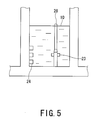
- Fig. 5 is an enlarged view of a pressure suppression pool illustrated in Fig. 4
- a reactor pressure vessel 21 is installed within a reactor containment vessel 14, and a safety valve 5 is provided in a pipe of a main steam system 11.
- a safety valve exhaust pipe 28 for introducing steam to a pressure suppression pool 10.
- Vent pipes 24 are provided in a wall of the pool, and a quencher 23 for facilitating steam condensation in the pressure suppression pool 10 is connected to the lower end of the safety valve exhaust pipe 28.
- reference numerals 22a and 22b denote main steam isolation valves.
- Fig. 6 illustrates the configuration of a safety valve
- Fig. 7 illustrates a safety valve drive system
- accumulators 3 and 4 are provided conventionally to supply an operating gas from a high-pressure nitrogen gas supply system 1 (1a, 1b), in order to open the safety valve 5 if an accident or a transient state occurs.
- the safety valve 5 is a nitrogen- and spring-operated type and is mounted on a pipe stand provided for the main steam pipe of the reactor containment vessel. An outlet side of the valve is formed as a flange connected to an exhaust pipe.
- the safety valve 5 is designed to automatically open (safety functions) if a valve inlet pressure exceeds a spring load.
- a piston 18 disposed in an air cylinder 19 mounted on the valve main unit and a valve shaft 17 are coupled with each other by means of a pull-up lever 16.
- the valve is configured so as to be opened (relief valve functions) by supplying nitrogen into the air cylinder 19 using an external signal. Supply of nitrogen into the air cylinder 19 is performed by operating a controlling solenoid valve.
- the safety valve 5 operates, in response to a simultaneous signal of a reactor water level "low” and a dry well pressure "high”, as the result of an auto-depressurization system actuating signal 9 being generated with an emergency core system pump enabled. If one of two solenoid valves for auto-depressurization functions 26a and 26b is opened in response to logic circuit output signals from the output signal cables 34b and 34c of logic circuits, a nitrogen gas is supplied from a high-pressure nitrogen gas supply system 1 or an accumulator 4, thereby forcing the safety valve 5 to open. Consequently, steam flows from the main steam system 11, in a direction shown by arrows S1 and S2, into the pressure suppression pool 10, thereby depressurizing the reactor pressure vessel.
- reference numeral 14 denotes a reactor containment vessel side and reference numeral 15 denotes a reactor building side.
- examples of conventional proposals of such a safety valve drive system described above include one described in Patent Document 1 (Japanese Patent Laid-Open No. 9-304584 ).
- the operating logic of a safety valve works in the manner that if at least one of three three-way solenoid valves operates, the safety valve is forced to open, thereby depressurizing the reactor pressure vessel.
- the current operating logic of a driving solenoid valve there is a possibility that if a fire occurs, a cable short-circuits to another cable and a false signal is generated, thus causing the solenoid valve to open mistakenly.
- the safety valve opens due to the malfunction of the solenoid valve, the depressurization of the reactor pressure vessel or the outflow of reactor water occurs, thus causing the water level of a reactor to drop.
- online maintenance becomes difficult to perform if a power source for driving an auto-depressurization system is lost.
- JP H10186087 A generally relates to prevention of the erroneous release of a main steam relief safety valve by provision of a test signal circuit on a start signal circuit for conducting a test of the start signal circuit of an automatic decompression system.
- US 6220280 B1 relates to a pressure relief system which includes a relief valve, a pilot valve for controlling the relief valve, and an isolation system for isolating the pilot valve.
- US 6644346 B1 relates to a safety valve which is opened and closed by a plurality of pilot parts which each are actuated by a pilot valve.
- US 6061412 A relates to a safety grade protection system for monitoring parameters indicative of the status of a core of a nuclear reactor, and reducing the criticality of the nuclear reaction when the onset of unsafe conditions are detected.
- JP H08233990 A generally relates to logics for making judgments regarding a reactor containment isolation cooling system.
- the present invention has been in of such problems as described above, and an object thereof is to provide a system or facility capable of improving the operating logic of a safety valve, enhancing the reliability thereof, and making compatible with online maintenance in order to eliminate the possibility of occurrence of a loss-of-coolant accident caused by the malfunction of a solenoid valve resulting from cable short-circuiting due to a fire or the like.
- the present invention provides a safety valve drive system according to claim 1.
- the phrase “relief valve actuating signal” may alternatively be read as “auto-depressurization system actuating signal,” depending on a reactor type different in the configuration of a safety system.
- a safety valve drive system of the present invention of the characters mentioned above, it is possible to eliminate the possibility of occurrence of a loss-of-coolant accident caused by the malfunction of a solenoid valve resulting from cable short-circuiting due to a fire or the like, thereby improving the safety valve in the operating logic thereof, enhancing the reliability thereof, and making compatible with online maintenance.
- Fig. 1 is a configuration diagram illustrating a safety valve drive system according to a first embodiment of the present invention.
- an operating logic of auto-depressurization functions of a safety valve installation of an opening line, enhancement of the operating logic of the auto-depressurization functions of the safety valve, a change of a driving source of the safety valve, a method of storing the driving source, and the like will be explained.
- a system A and a system B are provided as drive circuits for auto-depressurization functions 7 of a safety valve 5.
- These system-A and system-B drive circuits for auto-depressurization functions 7 are comprised of circuits based on auto-depressurization system actuating signals 33 (33(I), 33(II), 33(III) and 33(IV)) of four segments. The respective segments are composed so as to be physically and electrically independent of one another.
- Each drive circuit for auto-depressurization functions 7, to which actuating signals 9 (9(I), 9(II), 9(III) and 9(IV)) of an auto-depressurization system are input has multiplicity and electrical and physical independency.
- each drive circuit for auto-depressurization functions 7 is configured so that the functions thereof are not hampered even by a single failure of equipment or by the online maintenance of a power supply system.
- the safety valve drive system is configured so that a safety valve provided in a main steam system of a nuclear power plant is opened by supplying a driving gas using a pilot valve if an accident or a transient state occurs, thereby protecting a reactor against excessive pressure.
- the safety valve drive system includes a safety valve drive unit which operates in a state that the safety valve is opened in response to respective auto-depressurization system actuating signals for two or more segments among respective auto-depressurization system actuating signals 9 (9(I), 9(II), 9(III) and 9(IV)) for the four segments, and is closed in a state for an actuating signal for one or less segment among the auto-depressurization system actuating signals 9 for the four segments, and the safety valve drive system further includes cables 34 connected to this safety valve drive unit so as to transfer the auto-depressurization system actuating signals for the four segments.
- Fig. 1 shows safety valve driving gas supply systems 1a and 1b and a pilot valve driving gas supply system 2.
- accumulators for the auto-depressurization functions 4, 3 and 6, and the pilot valves (opening lines) 31a and 31b, and the pilot valves (for safety valve driving) 32a and 32b are provided in gas supply lines for the auto-depressurization functions 30, 8 and 29, respectively.
- the pilot valves (for safety valve driving) 32 (32a and 32b) for performing the opening/closing drive of the safety valve 5 are mounted on the driving gas supply line 30 of the safety valve.
- the pilot valves 32 open when supplied with a pilot valve driving gas, and a piston 18 and a valve shaft 17 within an air cylinder 19 of the safety valve are pulled up, thereby causing the safety valve 5 to open. If not supplied with the pilot valve driving gas, the pilot valves (for safety valve driving) 32 (32a, 32b) are closed and the safety valve 5 is also closed.
- Each drive circuit for the auto-depressurization functions 7 is comprised of eight solenoid valves 33 and is installed on a pilot valve driving gas supply line 29.
- the drive circuit supplies a gas from a gas supply system (for pilot valve driving) 2, in order to drive the pilot valve (for safety valve driving) 32.
- This configuration of the solenoid valves 33 is based on a so-called "2-out-of-4" logic. That is, the pilot valve driving gas is supplied to the pilot valve (for safety valve driving) 32 in response to the respective auto-depressurization system actuating signals for two or more segments among the auto-depressurization system actuating signals 9 for the four segments , and the safety valve 5 opens. In contrast, the pilot valve driving gas is not supplied to the pilot valve (for safety valve driving) 32 if an actuating signal for one or less segment among the auto-depressurization system actuating signals 9 for the four segments is received, and the safety valve 5 is closed.
- the operating logic of the safety valve 5 is made compatible with online maintenance with respect to a power supply and a signal for each safety system segment by setting the logic circuit for actuating the auto-depressurization functions of the safety valve 5 to a "2-out-of-4" logic. Thus, the reliability of the operating logic is improved.
- the safety valve drive unit is provided with the pilot valve 31 mounted on the driving gas supply line 30 of the safety valve 5 and adapted to open if supplied with a pilot valve driving gas and to close if not supplied with the pilot valve driving gas, and also provided with the pilot valve driving gas supply line for driving this pilot valve.
- the safety valve drive unit includes the pilot valve driving circuit arranged in the pilot valve driving gas supply line, so that a pilot valve driving gas is supplied to the pilot valve in response to the respective auto-depressurization system actuating signals for two or more segments among the auto-depressurization system actuating signals 9 for the four segments, and on the other hand, the pilot valve driving gas is not supplied to the pilot valve if an actuating signal for one or less segment among the auto-depressurization system actuating signals 9 for the four segments is received.
- an always-"open" opening line 27 and an always-"open” pilot valve (opening line) 31 are provided, so that the pilot valve is closed if the pilot valve driving gas is supplied to thereby open the safety valve 5.
- the safety valve drive unit comprises: an opening line provided on a gas supply line for the safety valve opening operation; a pilot valve provided on the opening line, so as to close if a pilot valve driving gas is supplied and open if the pilot valve driving gas is not supplied; a pilot valve driving gas supply line for driving the pilot valve; and a pilot valve driving circuit provided on the pilot valve driving gas supply line so as to operate in a manner such that the pilot valve driving gas is supplied to the pilot valve in response to the respective actuating signals for two or more segments among the actuating signals for the four segments, and the pilot valve driving gas is not supplied to the pilot valve if an actuating signal for one or less segment among the actuating signals for the four segments is received.
- the pilot valve (for safety valve driving) 32 and the pilot valve (opening line) 31 do not operate due to malfunction, the auto-depressurization system as a whole may fail to operate. Accordingly, it is possible to make this configuration as duplex structure.
- the present embodiment in this case is configured in the manner as illustrated in Fig. 1 , the pilot valves (for safety valve driving) 32 are arranged in parallel and the pilot valves (opening line) 31 are arranged in series, so that the safety valve 5 can be driven if either one of the two valves operates.
- two pilot valves on the opening line are arranged in series and two safety valve driving pilot valves are arranged in parallel, thereby providing safety valve drive units having duplex structure in preparation for the case that the safety valve drive unit fails to operate due to the malfunction of the pilot valve.
- a gas accumulator 6 is arranged so that gas can be stably supplied for a certain period of time even if the functions of the gas supply system (for pilot valve driving) 2 for supplying a gas to the pilot valve driving gas supply line 29 are lost.
- a safety valve drive system is installed such that an accumulator is disposed in a pilot valve driving gas supply line in preparation for loss in the functions of a pilot valve driving gas supply system.
- the safety valve can be improved in the operating logic thereof, enhanced in the reliability thereof, and made satisfactorily compatible with online maintenance.
- Fig. 2 is a configuration diagram illustrating a safety valve drive system according to a second embodiment of the present invention, in which like reference numerals are added to elements or members corresponding to those of the first embodiment mentioned above with reference to Fig. 1 , and duplicated explanations thereof are omitted hereunder.
- a drive circuit 12 for relief valve functions of a safety valve 5 includes generation of actuating signals for relief valve functions 13 composed of four segments and the circuits thereof, in which the respective segments have structures each physically and electrically independent of one another. Consequently, the drive circuit has multiplicity and electrical and physical independency, so that the functions of the drive circuit are not hampered even by an occurrence of a single failure of equipment or by the online maintenance of a power supply system.
- the present embodiment is a safety valve drive system in which a safety valve provided in the main steam system of a nuclear power plant is opened by supplying a driving gas by a pilot valve if an accident or a transient state occurs, thereby protecting a reactor against pressure application.
- the safety valve drive system comprises: a safety valve drive unit actuating the safety valve to be opened in response to respective relief valve pressure setpoint "high” actuating signals for two or more segments among respective relief valve pressure setpoint "high” actuating signals for the four segments, and to be placed in a closed state if an actuating signal for one or less segment among the relief valve pressure setpoint "high” actuating signals for the four segments is received; and cables connected to the safety valve drive unit and used to transfer the relief valve pressure setpoint "high” actuating signals for the four segments.
- Fig. 3 is a configuration diagram illustrating a safety valve drive system in accordance with an illustrative example, in which like reference numerals are added to elements or members corresponding to those of the first embodiment mentioned above with reference to Fig. 1 , and duplicated explanations thereof are omitted hereunder.
- a drive circuit 12 for relief valve functions of a safety valve 5 includes actuating signals 13 for relief valve functions composed of three segments and the circuits thereof, in which the respective segments have structures physically and electrically independent of one another. Consequently, the drive circuit has multiplicity and electrical and physical independency, so that the functions of the drive circuit are not hampered by a single failure of equipment. Further, this configuration may be also effective for the operating logic of an auto-depressurization system in a plant having a safety system divided into three segments.
Landscapes
- Engineering & Computer Science (AREA)
- General Engineering & Computer Science (AREA)
- Physics & Mathematics (AREA)
- Mechanical Engineering (AREA)
- Business, Economics & Management (AREA)
- Emergency Management (AREA)
- Plasma & Fusion (AREA)
- High Energy & Nuclear Physics (AREA)
- Structure Of Emergency Protection For Nuclear Reactors (AREA)
- Fluid-Driven Valves (AREA)
Claims (2)
- Système d'entraînement pour valve de sécurité adapté afin d'ouvrir une valve de sécurité (5) d'une centrale nucléaire en alimentant un gaz d'entraînement en utilisant une valve pilote à une occurrence d'un accident ou quand un état transitoire se produit, en protégeant ainsi un réacteur contre une application de pression, le système d'entrainement de valve de sécurité comprenant :une unité d'entraînement de valve de sécurité, comme moyen d'actionnement de valve de sécurité (5) adaptée afin de fonctionner d'une manière telle que la valve de sécurité (5) soit ouverte en réponse aux signaux d'actionnement (9) d'un système d'auto-dépressurisation respectif (7) pour deux ou plus segments parmi des signaux d'actionnement de système d'auto-dépressurisation respectifs (9) pour quatre segments (I-IV) et soit ouverte par un signal d'actionnement (9) de système d'auto-dépressurisation pour un ou moins segment parmi les signaux d'actionnement de système d'auto-dépressurisation (9) pour les quatre segments (I-IV) ; etdes câbles (34) connectés à l'unité d'entraînement pour valve de sécurité et adapté afin d'être utilisé pour transférer les signaux d'actionnement (9) de système d'auto-dépressurisation (7) pour les quatre segments (I-IV),caractérisé en ce que l'unité d'entraînement pour valve de sécurité comprend :une ligne d'ouverture (27) prévue pour une ligne d'alimentation n gaz (8, 30) pour une opération d'ouverture de valve de sécurité (5) ;une ligne d'alimentation en gaz d'entraînement pour valve pilote adaptée afin d'entraîner la valve pilote (31, 31a, 31b) prévue pour la ligne d'ouverture (27) de sorte qu'elle soit fermée quand un gaz d'entraînement de valve pilote est alimenté et qu'elle soit ouverte quand le gaz d'entraînement de valve pilote n'est pas alimenté ; etun circuit d'entraînement pour valve pilote prévu pour la ligne d'alimentation en gaz d'entraînement pour valve pilote, le circuit d'entraînement pour valve pilote étant adapté pour alimenter le gaz d'entraînement de valve pilote dans la valve pilote en réponse aux signaux d'actionnement respectifs (9) pour deux ou plus segments parmi les signaux d'actionnement (9) pour quatre segments (I-IV) et pour ne pas alimenter le gaz d'entraînement de valve pilote dans la valve pilote (31, 31a, 31b) si un signal d'actionnement (9) pour un ou moins segment parmi les signaux d'actionnement (9) pour les quatre segments (I-IV) est reçu.
- Système d'entraînement pour valve de sécurité selon la revendication 1, dans lequel un accumulateur (3, 4, 6) est installé dans la ligne d'alimentation en gaz d'entraînement pour valve pilote (8, 30) en préparation d'une perte des fonctions d'une alimentation de gaz d'entraînement pour valve pilote (1a, 1b, 2).
Applications Claiming Priority (2)
| Application Number | Priority Date | Filing Date | Title |
|---|---|---|---|
| JP2007160760 | 2007-06-18 | ||
| PCT/JP2008/061054 WO2008156086A1 (fr) | 2007-06-18 | 2008-06-17 | Système d'entraînement pour valve de sécurité |
Publications (3)
| Publication Number | Publication Date |
|---|---|
| EP2192594A1 EP2192594A1 (fr) | 2010-06-02 |
| EP2192594A4 EP2192594A4 (fr) | 2013-09-18 |
| EP2192594B1 true EP2192594B1 (fr) | 2014-08-27 |
Family
ID=40156245
Family Applications (1)
| Application Number | Title | Priority Date | Filing Date |
|---|---|---|---|
| EP20080765687 Not-in-force EP2192594B1 (fr) | 2007-06-18 | 2008-06-17 | Système d'entraînement pour valve de sécurité |
Country Status (4)
| Country | Link |
|---|---|
| US (1) | US8528588B2 (fr) |
| EP (1) | EP2192594B1 (fr) |
| JP (1) | JP4768855B2 (fr) |
| WO (1) | WO2008156086A1 (fr) |
Families Citing this family (9)
| Publication number | Priority date | Publication date | Assignee | Title |
|---|---|---|---|---|
| JP5676905B2 (ja) * | 2010-04-09 | 2015-02-25 | 株式会社東芝 | 逃し安全弁の駆動システム |
| CN102394117B (zh) * | 2011-08-04 | 2013-06-12 | 北京广利核系统工程有限公司 | 一种多功能驱动模块 |
| KR101234570B1 (ko) * | 2011-09-19 | 2013-02-19 | 한국원자력연구원 | 냉각재 상실사고 완화가 가능한 일체형 원자로 및 그 완화방법 |
| JP6208569B2 (ja) * | 2013-12-17 | 2017-10-04 | 日立Geニュークリア・エナジー株式会社 | 気体供給装置及び原子力プラントの空気又は窒素供給装置 |
| JP6370705B2 (ja) * | 2014-12-26 | 2018-08-08 | 日立Geニュークリア・エナジー株式会社 | バタフライ弁 |
| CN105546182B (zh) * | 2016-01-07 | 2017-12-08 | 中国能源建设集团广东省电力设计研究院有限公司 | 核电站系统阀门驱动控制设备 |
| JP6445986B2 (ja) * | 2016-02-05 | 2018-12-26 | 日立Geニュークリア・エナジー株式会社 | 原子力発電プラント |
| RU180577U1 (ru) * | 2017-09-18 | 2018-06-19 | Акционерное общество "Научно-производственное предприятие "Исток" имени А.И. Шокина" (АО "НПП "Исток" им. Шокина") | Клапан для разгерметизации электронных приборов |
| JP7756321B2 (ja) * | 2021-10-06 | 2025-10-20 | 国立大学法人東京科学大学 | 原子炉格納容器用ベントバルブシステム |
Family Cites Families (14)
| Publication number | Priority date | Publication date | Assignee | Title |
|---|---|---|---|---|
| CH589815A5 (fr) * | 1975-03-20 | 1977-07-15 | Sulzer Ag | |
| JPS60166892A (ja) | 1984-02-10 | 1985-08-30 | 株式会社日立製作所 | 蒸気逃し弁 |
| JPS633295A (ja) | 1986-06-24 | 1988-01-08 | 株式会社日立製作所 | 原子炉安全保護系 |
| JP2502224B2 (ja) * | 1991-09-19 | 1996-05-29 | 株式会社日立製作所 | 空気作動弁 |
| CA2088185C (fr) * | 1993-02-05 | 1999-08-31 | Clarence William Johnson | Vanne pilote a deux circuits |
| JPH08233990A (ja) | 1995-02-28 | 1996-09-13 | Hitachi Ltd | 原子炉安全システムとその作動状態表示方法 |
| US5590684A (en) * | 1995-09-01 | 1997-01-07 | Keystone International Holdings Corporation | Dual pilot manifold assembly for a safety relief valve |
| US6061412A (en) * | 1995-10-05 | 2000-05-09 | Westinghouse Electric Company Llc | Nuclear reaction protection system |
| JPH09304584A (ja) | 1996-05-16 | 1997-11-28 | Toshiba Corp | 原子力発電プラント主蒸気管の弁システム |
| JPH10186087A (ja) | 1996-12-26 | 1998-07-14 | Hitachi Ltd | 原子炉減圧系起動制御装置 |
| JPH11295481A (ja) | 1998-04-13 | 1999-10-29 | Mitsubishi Heavy Ind Ltd | 原子力発電プラント |
| DE19816463C1 (de) * | 1998-04-14 | 1999-06-02 | Siemens Ag | Federbelastetes Tandem-Steuerventil |
| US6220280B1 (en) * | 1999-05-12 | 2001-04-24 | Curtis-Wright Flow Control Corporation | Pilot operated relief valve with system isolating pilot valve from process media |
| US6550018B1 (en) * | 2000-02-18 | 2003-04-15 | The University Of Akron | Hybrid multiple redundant computer system |
-
2008
- 2008-06-17 WO PCT/JP2008/061054 patent/WO2008156086A1/fr not_active Ceased
- 2008-06-17 JP JP2009520488A patent/JP4768855B2/ja not_active Expired - Fee Related
- 2008-06-17 US US12/665,277 patent/US8528588B2/en not_active Expired - Fee Related
- 2008-06-17 EP EP20080765687 patent/EP2192594B1/fr not_active Not-in-force
Also Published As
| Publication number | Publication date |
|---|---|
| EP2192594A4 (fr) | 2013-09-18 |
| EP2192594A1 (fr) | 2010-06-02 |
| US20100181508A1 (en) | 2010-07-22 |
| JPWO2008156086A1 (ja) | 2010-08-26 |
| WO2008156086A1 (fr) | 2008-12-24 |
| US8528588B2 (en) | 2013-09-10 |
| JP4768855B2 (ja) | 2011-09-07 |
Similar Documents
| Publication | Publication Date | Title |
|---|---|---|
| EP2192594B1 (fr) | Système d'entraînement pour valve de sécurité | |
| US20020101951A1 (en) | Boiling water reactor nuclear power plant | |
| EP2495730B1 (fr) | Centrale nucléaire et procédé d'aide au fonctionnement pour une centrale nucléaire | |
| CN102298980B (zh) | 百万千瓦级数字化核电站反应堆保护退出的方法 | |
| CN103460298A (zh) | 核反应堆自动减压系统 | |
| US20110249784A1 (en) | Driving system of relief safety valve | |
| EP2602794B1 (fr) | Système de commande pour une centrale nucléaire | |
| CN111322437A (zh) | 减压阀 | |
| US4113561A (en) | Valve arrangement for a nuclear plant residual heat removal system | |
| US20120294409A1 (en) | Transient mitigation system for reactor | |
| JPH05307094A (ja) | 沸騰水型原子炉の原子炉冷却系 | |
| EP2339590B1 (fr) | Procédés de contrôle des concentrations en hydrogène dans un système de dégagement gazeux de réacteur nucléaire par injection d'air passive | |
| REC | Standard review plan | |
| KR20120090653A (ko) | 전기적 트립 솔레노이드밸브 차단블록장치 | |
| Cilliers | Benchmarking an expert fault detection and diagnostic system on the Three Mile Island accident event sequence | |
| JP2009176205A (ja) | 桁探索木の初期危険因子解析装置 | |
| CN210245082U (zh) | 一种核电站的超压保护系统和核电站 | |
| CN111810300B (zh) | 燃气轮机保护装置 | |
| KR100336332B1 (ko) | 원자로 가압기의 과압보호 및 안전 감압 밸브 시스템 | |
| JPS6119905A (ja) | タ−ビン制御装置 | |
| CN112309598A (zh) | 一种核电站的超压保护系统和核电站 | |
| JPH036324B2 (fr) | ||
| O'Brien et al. | PROTECTION INSTRUMENTATION SYSTEMS IN LIGHT-WATER-COOLED POWER REACTOR PLANTS. | |
| Ebersole et al. | An integrated safe shutdown heat removal system for light water reactors | |
| Eckert et al. | BACKFITTING OF INDEPENDENT RESIDUAL HEAT REMOVAL SYSTEMS IN WEST-GERMANY AND SWITZERLAND |
Legal Events
| Date | Code | Title | Description |
|---|---|---|---|
| PUAI | Public reference made under article 153(3) epc to a published international application that has entered the european phase |
Free format text: ORIGINAL CODE: 0009012 |
|
| 17P | Request for examination filed |
Effective date: 20100115 |
|
| AK | Designated contracting states |
Kind code of ref document: A1 Designated state(s): AT BE BG CH CY CZ DE DK EE ES FI FR GB GR HR HU IE IS IT LI LT LU LV MC MT NL NO PL PT RO SE SI SK TR |
|
| AX | Request for extension of the european patent |
Extension state: AL BA MK RS |
|
| DAX | Request for extension of the european patent (deleted) | ||
| A4 | Supplementary search report drawn up and despatched |
Effective date: 20130820 |
|
| RIC1 | Information provided on ipc code assigned before grant |
Ipc: G21D 3/04 20060101AFI20130813BHEP Ipc: F16K 17/10 20060101ALI20130813BHEP Ipc: G21D 1/00 20060101ALI20130813BHEP |
|
| GRAP | Despatch of communication of intention to grant a patent |
Free format text: ORIGINAL CODE: EPIDOSNIGR1 |
|
| INTG | Intention to grant announced |
Effective date: 20140415 |
|
| GRAS | Grant fee paid |
Free format text: ORIGINAL CODE: EPIDOSNIGR3 |
|
| GRAA | (expected) grant |
Free format text: ORIGINAL CODE: 0009210 |
|
| AK | Designated contracting states |
Kind code of ref document: B1 Designated state(s): AT BE BG CH CY CZ DE DK EE ES FI FR GB GR HR HU IE IS IT LI LT LU LV MC MT NL NO PL PT RO SE SI SK TR |
|
| REG | Reference to a national code |
Ref country code: GB Ref legal event code: FG4D |
|
| REG | Reference to a national code |
Ref country code: CH Ref legal event code: EP |
|
| REG | Reference to a national code |
Ref country code: AT Ref legal event code: REF Ref document number: 684857 Country of ref document: AT Kind code of ref document: T Effective date: 20140915 |
|
| REG | Reference to a national code |
Ref country code: IE Ref legal event code: FG4D |
|
| REG | Reference to a national code |
Ref country code: DE Ref legal event code: R096 Ref document number: 602008034106 Country of ref document: DE Effective date: 20141009 |
|
| REG | Reference to a national code |
Ref country code: SE Ref legal event code: TRGR |
|
| REG | Reference to a national code |
Ref country code: CH Ref legal event code: NV Representative=s name: FIAMMENGHI-FIAMMENGHI, CH |
|
| REG | Reference to a national code |
Ref country code: AT Ref legal event code: MK05 Ref document number: 684857 Country of ref document: AT Kind code of ref document: T Effective date: 20140827 |
|
| REG | Reference to a national code |
Ref country code: LT Ref legal event code: MG4D |
|
| REG | Reference to a national code |
Ref country code: NL Ref legal event code: VDEP Effective date: 20140827 |
|
| PG25 | Lapsed in a contracting state [announced via postgrant information from national office to epo] |
Ref country code: PT Free format text: LAPSE BECAUSE OF FAILURE TO SUBMIT A TRANSLATION OF THE DESCRIPTION OR TO PAY THE FEE WITHIN THE PRESCRIBED TIME-LIMIT Effective date: 20141229 Ref country code: ES Free format text: LAPSE BECAUSE OF FAILURE TO SUBMIT A TRANSLATION OF THE DESCRIPTION OR TO PAY THE FEE WITHIN THE PRESCRIBED TIME-LIMIT Effective date: 20140827 Ref country code: GR Free format text: LAPSE BECAUSE OF FAILURE TO SUBMIT A TRANSLATION OF THE DESCRIPTION OR TO PAY THE FEE WITHIN THE PRESCRIBED TIME-LIMIT Effective date: 20141128 Ref country code: NO Free format text: LAPSE BECAUSE OF FAILURE TO SUBMIT A TRANSLATION OF THE DESCRIPTION OR TO PAY THE FEE WITHIN THE PRESCRIBED TIME-LIMIT Effective date: 20141127 Ref country code: LT Free format text: LAPSE BECAUSE OF FAILURE TO SUBMIT A TRANSLATION OF THE DESCRIPTION OR TO PAY THE FEE WITHIN THE PRESCRIBED TIME-LIMIT Effective date: 20140827 Ref country code: BG Free format text: LAPSE BECAUSE OF FAILURE TO SUBMIT A TRANSLATION OF THE DESCRIPTION OR TO PAY THE FEE WITHIN THE PRESCRIBED TIME-LIMIT Effective date: 20141127 |
|
| PG25 | Lapsed in a contracting state [announced via postgrant information from national office to epo] |
Ref country code: CY Free format text: LAPSE BECAUSE OF FAILURE TO SUBMIT A TRANSLATION OF THE DESCRIPTION OR TO PAY THE FEE WITHIN THE PRESCRIBED TIME-LIMIT Effective date: 20140827 Ref country code: LV Free format text: LAPSE BECAUSE OF FAILURE TO SUBMIT A TRANSLATION OF THE DESCRIPTION OR TO PAY THE FEE WITHIN THE PRESCRIBED TIME-LIMIT Effective date: 20140827 Ref country code: AT Free format text: LAPSE BECAUSE OF FAILURE TO SUBMIT A TRANSLATION OF THE DESCRIPTION OR TO PAY THE FEE WITHIN THE PRESCRIBED TIME-LIMIT Effective date: 20140827 Ref country code: IS Free format text: LAPSE BECAUSE OF FAILURE TO SUBMIT A TRANSLATION OF THE DESCRIPTION OR TO PAY THE FEE WITHIN THE PRESCRIBED TIME-LIMIT Effective date: 20141227 Ref country code: HR Free format text: LAPSE BECAUSE OF FAILURE TO SUBMIT A TRANSLATION OF THE DESCRIPTION OR TO PAY THE FEE WITHIN THE PRESCRIBED TIME-LIMIT Effective date: 20140827 |
|
| PG25 | Lapsed in a contracting state [announced via postgrant information from national office to epo] |
Ref country code: NL Free format text: LAPSE BECAUSE OF FAILURE TO SUBMIT A TRANSLATION OF THE DESCRIPTION OR TO PAY THE FEE WITHIN THE PRESCRIBED TIME-LIMIT Effective date: 20140827 |
|
| PG25 | Lapsed in a contracting state [announced via postgrant information from national office to epo] |
Ref country code: DK Free format text: LAPSE BECAUSE OF FAILURE TO SUBMIT A TRANSLATION OF THE DESCRIPTION OR TO PAY THE FEE WITHIN THE PRESCRIBED TIME-LIMIT Effective date: 20140827 Ref country code: RO Free format text: LAPSE BECAUSE OF FAILURE TO SUBMIT A TRANSLATION OF THE DESCRIPTION OR TO PAY THE FEE WITHIN THE PRESCRIBED TIME-LIMIT Effective date: 20140827 Ref country code: CZ Free format text: LAPSE BECAUSE OF FAILURE TO SUBMIT A TRANSLATION OF THE DESCRIPTION OR TO PAY THE FEE WITHIN THE PRESCRIBED TIME-LIMIT Effective date: 20140827 Ref country code: IT Free format text: LAPSE BECAUSE OF FAILURE TO SUBMIT A TRANSLATION OF THE DESCRIPTION OR TO PAY THE FEE WITHIN THE PRESCRIBED TIME-LIMIT Effective date: 20140827 Ref country code: EE Free format text: LAPSE BECAUSE OF FAILURE TO SUBMIT A TRANSLATION OF THE DESCRIPTION OR TO PAY THE FEE WITHIN THE PRESCRIBED TIME-LIMIT Effective date: 20140827 Ref country code: SK Free format text: LAPSE BECAUSE OF FAILURE TO SUBMIT A TRANSLATION OF THE DESCRIPTION OR TO PAY THE FEE WITHIN THE PRESCRIBED TIME-LIMIT Effective date: 20140827 |
|
| REG | Reference to a national code |
Ref country code: DE Ref legal event code: R097 Ref document number: 602008034106 Country of ref document: DE |
|
| PG25 | Lapsed in a contracting state [announced via postgrant information from national office to epo] |
Ref country code: PL Free format text: LAPSE BECAUSE OF FAILURE TO SUBMIT A TRANSLATION OF THE DESCRIPTION OR TO PAY THE FEE WITHIN THE PRESCRIBED TIME-LIMIT Effective date: 20140827 |
|
| PLBE | No opposition filed within time limit |
Free format text: ORIGINAL CODE: 0009261 |
|
| STAA | Information on the status of an ep patent application or granted ep patent |
Free format text: STATUS: NO OPPOSITION FILED WITHIN TIME LIMIT |
|
| 26N | No opposition filed |
Effective date: 20150528 |
|
| PG25 | Lapsed in a contracting state [announced via postgrant information from national office to epo] |
Ref country code: SI Free format text: LAPSE BECAUSE OF FAILURE TO SUBMIT A TRANSLATION OF THE DESCRIPTION OR TO PAY THE FEE WITHIN THE PRESCRIBED TIME-LIMIT Effective date: 20140827 |
|
| REG | Reference to a national code |
Ref country code: DE Ref legal event code: R119 Ref document number: 602008034106 Country of ref document: DE |
|
| PG25 | Lapsed in a contracting state [announced via postgrant information from national office to epo] |
Ref country code: MC Free format text: LAPSE BECAUSE OF FAILURE TO SUBMIT A TRANSLATION OF THE DESCRIPTION OR TO PAY THE FEE WITHIN THE PRESCRIBED TIME-LIMIT Effective date: 20140827 |
|
| GBPC | Gb: european patent ceased through non-payment of renewal fee |
Effective date: 20150617 |
|
| PG25 | Lapsed in a contracting state [announced via postgrant information from national office to epo] |
Ref country code: LU Free format text: LAPSE BECAUSE OF FAILURE TO SUBMIT A TRANSLATION OF THE DESCRIPTION OR TO PAY THE FEE WITHIN THE PRESCRIBED TIME-LIMIT Effective date: 20150617 |
|
| REG | Reference to a national code |
Ref country code: IE Ref legal event code: MM4A |
|
| REG | Reference to a national code |
Ref country code: FR Ref legal event code: ST Effective date: 20160229 |
|
| PG25 | Lapsed in a contracting state [announced via postgrant information from national office to epo] |
Ref country code: IE Free format text: LAPSE BECAUSE OF NON-PAYMENT OF DUE FEES Effective date: 20150617 Ref country code: DE Free format text: LAPSE BECAUSE OF NON-PAYMENT OF DUE FEES Effective date: 20160101 Ref country code: GB Free format text: LAPSE BECAUSE OF NON-PAYMENT OF DUE FEES Effective date: 20150617 |
|
| PG25 | Lapsed in a contracting state [announced via postgrant information from national office to epo] |
Ref country code: FR Free format text: LAPSE BECAUSE OF NON-PAYMENT OF DUE FEES Effective date: 20150630 |
|
| PG25 | Lapsed in a contracting state [announced via postgrant information from national office to epo] |
Ref country code: BE Free format text: LAPSE BECAUSE OF FAILURE TO SUBMIT A TRANSLATION OF THE DESCRIPTION OR TO PAY THE FEE WITHIN THE PRESCRIBED TIME-LIMIT Effective date: 20140827 |
|
| PGFP | Annual fee paid to national office [announced via postgrant information from national office to epo] |
Ref country code: FI Payment date: 20160609 Year of fee payment: 9 Ref country code: CH Payment date: 20160613 Year of fee payment: 9 |
|
| PGFP | Annual fee paid to national office [announced via postgrant information from national office to epo] |
Ref country code: SE Payment date: 20160613 Year of fee payment: 9 |
|
| PG25 | Lapsed in a contracting state [announced via postgrant information from national office to epo] |
Ref country code: MT Free format text: LAPSE BECAUSE OF FAILURE TO SUBMIT A TRANSLATION OF THE DESCRIPTION OR TO PAY THE FEE WITHIN THE PRESCRIBED TIME-LIMIT Effective date: 20140827 |
|
| PG25 | Lapsed in a contracting state [announced via postgrant information from national office to epo] |
Ref country code: HU Free format text: LAPSE BECAUSE OF FAILURE TO SUBMIT A TRANSLATION OF THE DESCRIPTION OR TO PAY THE FEE WITHIN THE PRESCRIBED TIME-LIMIT; INVALID AB INITIO Effective date: 20080617 |
|
| PG25 | Lapsed in a contracting state [announced via postgrant information from national office to epo] |
Ref country code: TR Free format text: LAPSE BECAUSE OF FAILURE TO SUBMIT A TRANSLATION OF THE DESCRIPTION OR TO PAY THE FEE WITHIN THE PRESCRIBED TIME-LIMIT Effective date: 20140827 |
|
| REG | Reference to a national code |
Ref country code: SE Ref legal event code: EUG |
|
| PG25 | Lapsed in a contracting state [announced via postgrant information from national office to epo] |
Ref country code: FI Free format text: LAPSE BECAUSE OF NON-PAYMENT OF DUE FEES Effective date: 20170617 |
|
| REG | Reference to a national code |
Ref country code: CH Ref legal event code: PL |
|
| PG25 | Lapsed in a contracting state [announced via postgrant information from national office to epo] |
Ref country code: SE Free format text: LAPSE BECAUSE OF NON-PAYMENT OF DUE FEES Effective date: 20170618 |
|
| PG25 | Lapsed in a contracting state [announced via postgrant information from national office to epo] |
Ref country code: LI Free format text: LAPSE BECAUSE OF NON-PAYMENT OF DUE FEES Effective date: 20170630 Ref country code: CH Free format text: LAPSE BECAUSE OF NON-PAYMENT OF DUE FEES Effective date: 20170630 |