EP2192665A1 - Bodeneinbaukassette für elektrische Installationsgeräte - Google Patents
Bodeneinbaukassette für elektrische Installationsgeräte Download PDFInfo
- Publication number
- EP2192665A1 EP2192665A1 EP09013071A EP09013071A EP2192665A1 EP 2192665 A1 EP2192665 A1 EP 2192665A1 EP 09013071 A EP09013071 A EP 09013071A EP 09013071 A EP09013071 A EP 09013071A EP 2192665 A1 EP2192665 A1 EP 2192665A1
- Authority
- EP
- European Patent Office
- Prior art keywords
- wall
- lid
- spring tongue
- floor installation
- housing
- Prior art date
- Legal status (The legal status is an assumption and is not a legal conclusion. Google has not performed a legal analysis and makes no representation as to the accuracy of the status listed.)
- Granted
Links
Images

Classifications
-
- H—ELECTRICITY
- H02—GENERATION; CONVERSION OR DISTRIBUTION OF ELECTRIC POWER
- H02G—INSTALLATION OF ELECTRIC CABLES OR LINES, OR OF COMBINED OPTICAL AND ELECTRIC CABLES OR LINES
- H02G3/00—Installations of electric cables or lines or protective tubing therefor in or on buildings, equivalent structures or vehicles
- H02G3/02—Details
- H02G3/08—Distribution boxes; Connection or junction boxes
- H02G3/18—Distribution boxes; Connection or junction boxes providing line outlets
- H02G3/185—Floor outlets and access cups
-
- H—ELECTRICITY
- H02—GENERATION; CONVERSION OR DISTRIBUTION OF ELECTRIC POWER
- H02G—INSTALLATION OF ELECTRIC CABLES OR LINES, OR OF COMBINED OPTICAL AND ELECTRIC CABLES OR LINES
- H02G3/00—Installations of electric cables or lines or protective tubing therefor in or on buildings, equivalent structures or vehicles
- H02G3/02—Details
- H02G3/08—Distribution boxes; Connection or junction boxes
- H02G3/14—Fastening of cover or lid to box
Definitions
- the invention relates to a floor installation cassette for electrical installation devices having at least two relatively movable components, in particular a housing and an insertable into the housing cover, wherein the components at least partially made of electrically conductive material.
- a generic floor installation cassette is for example from the European patent application EP 1 811 624 A2 known.
- EP 1 811 624 A2 European patent application
- all components must be grounded. This also applies, for example, to a lid of the installation cassette and a cord outlet possibly movably mounted on the lid.
- a potential equalization is provided via a flexible conductor.
- a flexible conductor can provide a reliable equipotential bonding, attaching the flexible But ladder is time consuming and the flexible conductor can interfere with the use of the floor installation cassette or its installation.
- a floor installation cassette for electrical installation equipment is to be provided, in which a potential equalization between the individual components can be produced with little effort.
- a floor installation cassette for electrical installation equipment with at least two relatively movable components, in particular a housing and a lid insertable into the housing is provided, wherein the components at least partially made of electrically conductive material, in which between the relatively movable components an electrically conductive sliding contact is provided.
- a potential equalization between the individual components can be produced in a surprisingly simple manner.
- the contact resistance of such a sliding contact is sufficient to meet the legal requirements.
- the sliding contact establishes a conductive connection between two components through a resilient contact point which rests on a contact track. If the components, for example the cover and the housing, are moved relative to one another, then the resilient contact point can move along the contact track. The electrical contact between the cover and the housing and thus the required equipotential bonding is maintained during a relative movement of the cover and housing.
- a potential equalization can be done by simply placing the contact point on the contact track, which is conveniently effected when inserting the lid into the housing.
- the floor installation cassette according to the invention is thus much easier To mount as known floor installation cassettes, since it can be dispensed with the connection of separate, flexible cable.
- a lid and housing in the context of the invention are generally understood cover, caps, flaps or the like, which are mounted on a housing of a floor mounting cassette to open an opening in the housing either or close or even to a relative position of the lid and housing to change each other.
- the earthing concept according to the invention can generally be applied to components of floor installation cassettes which can be displaced relative to one another.
- a potential equalization between a lower part of the floor installation cassette, which is connected to a raw floor of a housing, and a relative to the lower part in height adjustable upper part of a housing by means of a sliding contact can be realized.
- the grounding concept according to the invention can of course be generally applied to housing for electrical installations with two relatively movable components, in which case a sliding contact realized by means of spring tongues is provided between the two components in order to produce a low-resistance electrical connection for the purpose of grounding between the components.
- These spring tongues are advantageously punched out of the material of the components themselves, so that no separate components more for the production of an electrical contact between the relatively movable components is required.
- the spring tongues are then formed integrally with a wall of the respective component.
- the at least one sliding contact between the housing and the cover is arranged.
- the components in particular the cover and the housing, have two mutually substantially parallel walls and an opening direction of the components, the sliding contact being arranged on one of the two walls.
- the sliding contact has a spring tongue which is fastened to a wall.
- the spring tongue is formed integrally with the wall.
- the spring tongue can be cut out, for example by means of a generally U-shaped section of the wall of the lid or the housing.
- Such a cut can be performed for example by means of laser tools, so that the attachment of the spring tongue can be integrated in a simple manner in the manufacturing process of the lid or the housing.
- the spring tongue is provided in the region of its free end with a bulge whose convex side faces the opposite contact track.
- a contact point By means of a bulge, a contact point can be created, which rests resiliently on the contact track on the opposite wall due to its arrangement on the spring tongue.
- the bulge can be formed on the back of an impression in the spring tongue.
- the spring tongue in the plan view of the wall on a curved shape.
- an end of the spring tongue connected to the wall can be moved from the edge of the wall into its center to ensure a stable arrangement. Nevertheless, the free end can be arranged in the region of an edge of the wall.
- a curved shape of the spring tongue thereby makes it possible to arrange the contact point, for example, below a rotation axis in order to ensure that the contact track is still contacted by the contact point, even at large opening angles, and an equipotential bonding is thereby produced. This is particularly advantageous when the lid is pivotally attached to the housing.
- the cover has a cable outlet flap, which is arranged pivotably on the cover, wherein at least one sliding contact between cable outlet flap and cover is provided.
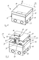
- FIG. 1 shows a floor installation cassette 10 according to the invention, which has a housing 12 and a lid 14 inserted into the housing.
- the lid 14 is pivotally inserted into the housing 12.
- a Jardinauslassklappe 16 is arranged on the lid 14 itself.
- the housing 12 consists of a lower part 18 and a top 20.
- the upper part 20 and the lower part 18 can telescope into one another.
- the lid 14 is inserted into an upwardly open frame of the upper part 20.
- All components of the floor installation cassette 10 consist of electrically conductive and galvanized or stainless steel sheet.
- the floor installation cassette 10 is mounted on the bare floor of a building before applying a screed by the lower part 18 is connected to the unfinished floor. Cable ducts are also fixed to the subfloor and then open at openings 22 in the lower part 18, which in the illustration of Fig. 1 are still closed with break-out pieces of sheet metal.
- the upper part 20 is then leveled relative to the unfinished floor or relative to the lower part 18 in height, so that the upper edge of the upper part 20 is flush with a screed surface provided.
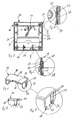
- a flexible equipotential bonding cable 24 is provided between the lower part 18 and the upper part 20 in a conventional manner.
- the lower part 18 is connected in a manner not shown with a ground wire.
- two sliding contacts 26 are provided between the cover 14 and the upper part 20 of the housing 12, of which in the Fig. 2 only one is recognizable.
- two further sliding contacts 28 are provided, of which in Fig. 2 only one is recognizable.
- the sliding contact 26 connects a wall 30 of the lid 14 electrically with a wall 32 of the upwardly open frame of the upper part 20.
- the two walls 30, 32 are arranged parallel to each other and also parallel to a Opening direction of the lid 14 is arranged.
- the walls 30, 32 thus remain in their mutually parallel position, even if they are pivoted to each other.
- the sliding contact 26 can thereby effect a potential equalization between the cover 14 and the upper part 20 of the housing 12.
- the cover 14 is symmetrical and on a wall 30 opposite wall 34 of the further sliding contact is arranged, which causes an electrical connection to the wall 36 of the upwardly open frame of the upper part 20 and in the representation of Fig. 2 can not be seen.
- the sliding contact 28 is arranged on a wall 38 of the cable outlet flap 16, which is arranged parallel to a wall 40 of the lid 14.
- Another, in the presentation of the Fig. 2 only in sections to be recognized sliding contact is disposed on a wall 42 of the Jardinauslassklappe 16, which is opposite to the wall 38.
- the wall 42 is in turn arranged parallel to a wall 44 on the cover 14 and the sliding contact establishes an electrical connection between the walls 42 and 44.
- the sliding contacts 26, 28 are realized on the lid 14 and on the Jardinauslassklappe 16 each by means of a spring tongue which forms a resilient contact point with a bulge at its free end, which permanently on the respectively adjacent wall 32, 36 of the upper part 20th or on the wall 40, 44 of the lid 14 and thereby during the entire opening operation and in the open and closed state of the lid 14 and the Jardinauslassklappe 16 a Potential equalization between the Jardinauslassklappe 16, the lid 14 and the housing 12 of the floor installation cassette 10 ensures.
- a contact resistance of the sliding contacts 26, 28 is in principle greater than the contact resistance of the flexible copper cable 24, which electrically connects the lower part 18 and the upper part 20, the contact resistance of the sliding contacts 26, 28 is sufficiently low to ensure a reliable potential equalization and the comply with applicable safety regulations.
- the presentation of the Fig. 3 shows a plan view of the sectional plane III-III of Fig. 1 and in addition to the two sliding contacts 26, 28, the two other sliding contacts 46, 48 can be seen.
- the sliding contact 46 is arranged opposite the sliding contact 28 and, like this, ensures an electrical connection of the cable outlet flap 16 to the cover 14.
- the sliding contact 48 is arranged opposite the sliding contact 26 and, like this, ensures an electrical connection between the cover 14 and the upper part 20 of the housing 12.
- the walls 30 and 34 of the lid 14 which are arranged parallel to the walls 32, 36 of the upper part 20.
- the sliding contact 26 ensures an electrical connection between the walls 30, 32, and the sliding contact 48 ensures an electrical connection between the walls 34, 36.
- Fig. 4 shows an enlarged view of the detail IV Fig. 3 , Evident is a portion of the wall 32 of the upper part 20 and a portion of the wall 30 of the lid 14. integral with the wall 30, a spring tongue 50 is formed, which by means of a generally U-shaped section, see Fig. 2 , is cut out of the wall 30.
- the spring tongue 50 carries at its free end a bulge 52, the convex side of the wall 32 faces.
- the bulge 52 is formed by an impression on, the wall 32 opposite side of the spring tongue 50.
- the bulge 52 is located on the inside of the wall 32 at.
- the spring tongue 50 is thereby deflected from its rest position to the left, ie away from the wall 32.
- the material elasticity of the material of the wall 30 thereby ensures a bias of the bulge 52 in the direction of the wall 32 of the upper part 20.
- Such a spring bias on the one hand ensures a low electrical contact resistance and on the other manufacturing tolerances of the cover 14 and upper part 20 can be compensated ,
- FIG. 5 shows the detail V out Fig. 3 in an enlarged view.
- a portion of the wall 40 of the lid 14 and a portion of the wall 38 of the cable outlet flap 16 can be seen.
- a spring tongue 54 is formed, which is formed by means of a U-shaped section in the wall 38, see Fig. 2 ,
- the spring tongue 54 carries at its free end a bulge 56 which is realized by an impression and the convex side of which rests against the wall 40.
- the Jardinauslassklappe 16 is guided by means of two bolts 58 in slide tracks in the lid 14, which are formed in the form of curved slots, see Fig. 2 , When you open the Jardinauslassklappe 16 this is thus to their in the representation of Fig. 2 the upper right edge lying above pivoted, with the bolts 58 along the curved slots in the walls 40, 44 of the cover 14 move. The bulges 56 slide along the wall 40 in order to bring about permanent potential equalization.
- the presentation of the Fig. 6 shows the Jardinauslassklappe 16 in an enlarged view.
- the Jardinauslassklappe 16 has a U-shaped main part 60 and a resting on the base of the main part 60 cover plate 62.
- the cover plate 62 is approximately as large as the base of the U-shaped main part 60.
- the spring tongue 54 is formed by means of a U-shaped cut in one of the legs of the main part 60, wherein the two legs of the main part 60 each perpendicular to the base or to Cover plate 62 are arranged.
- the U-shaped section extends into the base of the main part 60 inside.
- the spring tongue 54 thereby extends from the edge of the base of the main part 60 and extends until shortly before the lower edge boundary of the leg of the main part 60.
- the U-shaped section with which the spring tongue 54 is cut out of the material of the wall of the main part 60 has in the region of the end connected to the main part 60 end of the spring tongue 54 significantly widened portions 64. In this area, the cut, for example by means of a laser, set or be completed and in this area, the main part 60 is sufficiently stable in order to make the cut wider.
- the bulge 56 is arranged adjacent to a passage opening 66 in the leg of the main part 60 of the cable outlet flap 16.
- the passage opening 66 receives the threaded bolt 58 in the mounted state of the cable outlet flap 16.
- the bulge 56 can thereby be guided adjacent to the curved elongated holes in the walls 40, 44 of the lid 14 during opening and closing of the cable outlet flap 16. Even with large opening angles of the cable outlet flap 16, the bulge 56 is thereby still reliably on the wall 40 of the lid 14 with its convex side.
- a shoulder 68 on the main part 60 is intended to be able to lock the cable outlet flap 16 in the open state at the upwardly open frame of the upper part 20. If cables are inserted through the cable outlet flap 16 into the interior of the floor installation cassette 10, this ensures that the cable outlet flap 16 does not collapse even under load and damages the insulation of the cable being carried.
- the presentation of the Fig. 8 shows the cable outlet flap 16 in a side view. It can be clearly seen that the spring tongue 54 extends from the base of the main part 60 and then extends to just before the lower edge of the leg of the main part 60.
- the base of the main part 60 has two projections 70 which engage under a cover plate of the lid 14 and hold the cable outlet flap 16 on the lid 14 even in the unfolded state.
- the presentation of the Fig. 9 shows the lid 14 in a view obliquely from above.
- Good to see is the formation of a spring tongue 50 in the wall 30.
- the spring tongue 50 see also Fig. 10 , In this case has a curved shape and the free end of the spring tongue 50 with the bulge 52 is adjacent to a through hole 72 in the wall 30 is arranged.
- the passage opening 72 receives in the assembled state of the lid 14 on a stub axle, which engages in a recess in the peripheral frame of the upper part 20, see Fig. 1 , and thereby forms a pivot axis of the lid 14.
- the recess in the context of the upper part 20 is not circular, but designed approximately slot-shaped to allow a superimposed translational / rotational movement of the lid 14 when unfolded.
- the arrangement of the bulge 52 adjacent to the passage opening 72 or the stub axle arranged in the passage opening 72 makes it possible for the bulge 52 to engage the wall of the upper part 20 even when the cover 14 is fully open to thereby ensure a reliable electrical contact and equipotential bonding between the cover 14 and housing 12.
- the spring tongue 50 is cut out of the wall 30 by means of a generally U-shaped section.
- the cut has clearly widened regions which mark the starting point and the end point of the cut.
- these widened regions 74 can be punched out and a laser can then, starting from these recesses 74, perform the U-like cut, as a result of which the spring tongue 50 is produced.
- a further spring tongue 76 with a button-like bulge on the lid 14 can be seen.
- This further spring tongue 76 is not primarily intended for equipotential bonding between the cover 14 and housing 12, but ensures in the closed state of the lid 14 for its exact positioning.
- the bulge 78 engages in the closed state of the lid in a through hole 80 on the peripheral frame of the upper part 20 partially and thereby defines a closed position of the lid 14. This can ensure that a cover plate of the lid 14 in the closed state exactly aligned with the upper edges of the peripheral frame of the upper part 20. Since the bulge 78 engages partially in the passage opening 80, a certain release force is required to open the lid 14 can.
- the spring tongue 76 with the bulge 78 of course also contributes to the potential equalization between the cover 14 and the housing 12 at.
- the reduction of the contact resistance by the spring tongue 76 is not required to ensure a reliable equipotential bonding, this is sufficient for the two sliding contacts on the lid 14, which arranged by means of the spring tongue 50, the bulge 52 and a mirror symmetry in the opposite wall 34 of the lid further Spring tongue are realized.
Landscapes
- Engineering & Computer Science (AREA)
- Architecture (AREA)
- Civil Engineering (AREA)
- Structural Engineering (AREA)
- Connector Housings Or Holding Contact Members (AREA)
- Coupling Device And Connection With Printed Circuit (AREA)
- Dry Shavers And Clippers (AREA)
- Relay Circuits (AREA)
Abstract
Description
- Die Erfindung betrifft eine Bodeneinbaukassette für elektrische Installationsgeräte mit wenigstens zwei relativ zueinander bewegbaren Bauteilen, insbesondere einem Gehäuse und einem in das Gehäuse einsetzbaren Deckel, wobei die Bauteile wenigstens abschnittsweise aus elektrisch leitfähigem Material bestehen.
- Eine gattungsgemäße Bodeneinbaukassette ist beispielsweise aus der europäischen Offenlegungsschrift
EP 1 811 624 A2 bekannt. Bei gattungsgemäßen Bodeneinbaukassetten müssen alle Bauteile geerdet werden. Dies gilt beispielsweise auch für einen Deckel der Einbaukassette und einen eventuell beweglich am Deckel angeordneten Schnurauslass. Üblicherweise wird lediglich eines der Bauteile, beispielsweise das Gehäuse, mit einem Erdungskabel verbunden und zwischen den einzelnen Bauteilen, speziell dem Gehäuse, einem Deckel und einem eventuellen Schnurauslass, wird ein Potentialausgleich über einen flexiblen Leiter vorgesehen. Mittels solcher flexibler Leiter lässt sich zwar ein zuverlässiger Potentialausgleich bereitstellen, das Anbringen der flexiblen Leiter ist aber zeitaufwändig und der flexible Leiter kann bei der Benutzung der Bodeneinbaukassette oder deren Installation stören. - Mit der Erfindung soll eine Bodeneinbaukassette für elektrische Installationsgeräte bereitgestellt werden, bei der mit geringem Aufwand ein Potentialausgleich zwischen den einzelnen Bauteilen hergestellt werden kann.
- Erfindungsgemäß ist hierzu eine Bodeneinbaukassette für elektrische Installationsgeräte mit wenigstens zwei relativ zueinander bewegbaren Bauteilen, insbesondere einem Gehäuse und einem in das Gehäuse einsetzbaren Deckel, vorgesehen, wobei die Bauteile wenigstens abschnittsweise aus elektrisch leitfähigem Material bestehen, bei der zwischen den relativ zueinander bewegbaren Bauteilen ein elektrisch leitfähiger Schleifkontakt vorgesehen ist.
- Durch Vorsehen eines Schleifkontakts zwischen den Bauteilen, insbesondere zwischen Deckel und Gehäuse, lässt sich auf überraschend einfache Weise ein Potentialausgleich zwischen den einzelnen Bauteilen herstellen. Überraschenderweise reicht der Übergangswiderstand eines solchen Schleifkontakts aus, um die gesetzlichen Anforderungen zu erfüllen. Der Schleifkontakt stellt eine leitende Verbindung zwischen zwei Bauteilen durch einen federnden Kontaktpunkt her, der auf einer Kontaktbahn aufsitzt. Werden die Bauteile, beispielsweise der Deckel und das Gehäuse, gegeneinander bewegt, so kann sich der federnde Kontaktpunkt entlang der Kontaktbahn bewegen. Der elektrische Kontakt zwischen Deckel und Gehäuse und damit der erforderliche Potentialausgleich bleibt während einer Relativbewegung von Deckel und Gehäuse aber erhalten. Ein Potentialausgleich kann durch einfaches Aufsetzen des Kontaktpunktes auf die Kontaktbahn erfolgen, was zweckmäßigerweise beim Einsetzen des Deckels in das Gehäuse bewirkt wird. Die erfindungsgemäße Bodeneinbaukassette ist damit wesentlich einfacher zu montieren als bekannte Bodeneinbaukassetten, da auf das Verbinden separater, flexibler Kabel verzichtet werden kann. Als Deckel und Gehäuse im Sinne der Erfindung werden allgemein Deckel, Kappen, Klappen oder dergleichen verstanden, die an einem Gehäuse einer Bodeneinbaukassette montiert sind, um eine Öffnung im Gehäuse wahlweise zu öffnen oder zu verschließen oder auch nur um eine relative Lage von Deckel und Gehäuse zueinander verändern zu können. Das erfindungsgemäße Erdungskonzept lässt sich selbstverständlich allgemein bei relativ zueinander verschiebbaren Bauteilen von Bodeneinbaukassetten anwenden. Beispielsweise kann ein Potentialausgleich zwischen einem Unterteil der Bodeneinbaukassette, das mit einem Rohboden eines Gehäuses verbunden wird, und einem relativ zum Unterteil in der Höhe verstellbaren Oberteil eines Gehäuses mittels eines Schleifkontakts realisiert werden. Das erfindungsgemäße Erdungskonzept lässt sich selbstverständlich allgemein auf Gehäuse für Elektroinstallationen mit zwei relativ zueinander beweglichen Bauteilen anwenden, wobei dann zwischen den beiden Bauteilen ein mittels Federzungen realisierter Schleifkontakt vorgesehen ist, um eine niederohmige elektrische Verbindung zum Zwecke der Erdung zwischen den Bauteilen herzustellen. Diese Federzungen sind vorteilhafterweise aus dem Material der Bauteile selbst herausgestanzt, so dass keine separaten Bauteile mehr für die Herstellung eines elektrischen Kontakts zwischen den relativ zueinander beweglichen Bauteilen erforderlich ist. Die Federzungen sind dann einstückig mit einer Wandung des jeweiligen Bauteils gebildet.
- In Weiterbildung der Erfindung ist der wenigstens eine Schleifkontakt zwischen Gehäuse und Deckel angeordnet.
- In Weiterbildung der Erfindung weisen die Bauteile, insbesondere der Deckel und das Gehäuse, zwei zueinander und zu einer Offnungsrichtung der Bauteile im Wesentlichen parallele Wandungen auf, wobei der Schleifkontakt an einer der beiden Wandungen angeordnet ist.
- Auf diese Weise verändert sich ein Abstand der zueinander parallelen Wandungen während des Öffnungsvorgangs beispielsweise des Deckels nicht und ein Schleifkontakt kann während des gesamten Öffnungsvorgangs einen zuverlässigen Potentialausgleich sicherstellen.
- In Weiterbildung der Erfindung weist der Schleifkontakt eine Federzunge auf, die an einer Wandung befestigt ist.
- Mittels einer Federzunge lässt sich ein konstruktiv einfaches und zuverlässig federndes Kontaktelement bereitstellen.
- In Weiterbildung der Erfindung ist die Federzunge einstückig mit der Wandung gebildet.
- Auf diese Weise wird für die Federzunge kein separates Bauteil benötigt und die Federzunge kann beispielsweise mittels eines allgemein U-förmigen Schnitts aus der Wandung des Deckels oder des Gehäuses herausgeschnitten werden. Ein solcher Schnitt kann beispielsweise mittels Laserwerkzeugen durchgeführt werden, so dass das Anbringen der Federzunge in einfacher Weise in den Herstellungsprozess des Deckels oder des Gehäuses integriert werden kann.
- In Weiterbildung der Erfindung ist die Federzunge im Bereich ihres freien Endes mit einer Auswölbung versehen, deren konvexe Seite der gegenüberliegenden Kontaktbahn zugewandt ist.
- Mittels einer Auswölbung kann ein Kontaktpunkt geschaffen werden, der aufgrund seiner Anordnung an der Federzunge federnd auf der Kontaktbahn auf der gegenüberliegenden Wandung anliegt. Die Auswölbung kann auf der Rückseite einer Einprägung in die Federzunge ausgebildet sein.
- Auf diese Weise wird für die Ausbildung des Kontaktpunktes selbst kein separates Bauteil benötigt.
- In Weiterbildung der Erfindung weist die Federzunge in der Draufsicht auf die Wandung eine gebogene Form auf.
- Durch Vorsehen einer gebogenen Form kann ein mit der Wandung verbundenes Ende der Federzunge vom Rand der Wandung aus in deren Mitte gerückt werden, um eine stabile Anordnung zu gewährleisten. Dennoch kann das freie Ende im Bereich einer Kante der Wandung angeordnet werden. Eine gebogene Form der Federzunge ermöglicht es dadurch, den Kontaktpunkt beispielsweise unterhalb einer Drehachse anzuordnen, um auch bei großen Öffnungswinkeln sicherzustellen, dass die Kontaktbahn noch vom Kontaktpunkt kontaktiert wird und dadurch ein Potentialausgleich hergestellt ist. Dies ist besonders dann vorteilhaft, wenn der Deckel an dem Gehäuse schwenkbar befestigt ist.
- In Weiterbildung der Erfindung weist der Deckel eine Kabelauslassklappe auf, die schwenkbar am Deckel angeordnet ist, wobei wenigstens ein Schleifkontakt zwischen Kabelauslassklappe und Deckel vorgesehen ist.
- Weitere Merkmale und Vorteile der Erfindung ergeben sich aus den Ansprüchen und der folgenden Beschreibung einer bevorzugten Ausführungsform der Erfindung im Zusammenhang mit den Zeichnungen. In den Zeichnungen zeigen:
- Fig. 1
- eine Ansicht einer erfindungsgemäßen Bodeneinbaukassette von schräg oben,
- Fig. 2
- die Bodeneinbaukassette der
Fig. 1 in teilweise auseinander gezogener Darstellung, - Fig. 3
- eine Draufsicht auf die Schnittebene III-III in
Fig. 1 , - Fig. 4
- die vergrößerte Einzelheit IV aus
Fig. 3 , - Fig. 5
- die vergrößerte Einzelheit V aus
Fig. 3 , - Fig. 6
- eine Ansicht der Kabelauslassklappe der Bodeneinbaukassette der
Fig. 1 von schräg oben, - Fig. 7
- die vergrößerte Einzelheit VII aus
Fig. 6 , - Fig. 8
- eine Seitenansicht der Kabelauslassklappe der
Fig. 6 , - Fig. 9
- eine Ansicht des Deckels der Bodeneinbaukassette der
Fig. 1 von schräg oben, - Fig. 10
- die vergrößerte Einzelheit X der
Fig. 9 und - Fig. 11
- eine Seitenansicht des Deckels der
Fig. 9 . - Die Darstellung der
Fig. 1 zeigt eine erfindungsgemäße Bodeneinbaukassette 10, die ein Gehäuse 12 und einen in das Gehäuse eingesetzten Deckel 14 aufweist. Der Deckel 14 ist schwenkbar in das Gehäuse 12 eingesetzt. Am Deckel 14 selbst ist wiederum schwenkbar eine Kabelauslassklappe 16 angeordnet. - Das Gehäuse 12 besteht aus einem Unterteil 18 und einem Oberteil 20. Das Oberteil 20 und das Unterteil 18 können teleskopartig ineinander gleiten. Der Deckel 14 ist in einen nach oben offenen Rahmen des Oberteils 20 eingesetzt. Im Wesentlichen alle Bauteile der Bodeneinbaukassette 10 bestehen aus elektrisch leitfähigem und verzinktem oder nichtrostendem Stahlblech.
- Die Bodeneinbaukassette 10 wird vor Ausbringen eines Estrichs auf dem Rohboden eines Gebäudes montiert, indem das Unterteil 18 mit dem Rohboden verbunden wird. Kabelkanäle werden ebenfalls auf dem Rohboden befestigt und münden dann an Öffnungen 22 im Unterteil 18, die in der Darstellung der
Fig. 1 noch mit ausbrechbaren Blechstücken verschlossen sind. Das Oberteil 20 wird dann relativ zum Rohboden beziehungsweise relativ zum Unterteil 18 in der Höhe nivelliert, so dass die Oberkante des Oberteils 20 bündig mit einer vorgesehenen Estrichoberfläche ist. - Um die sichere Erdung aller Bestandteile der Bodeneinbaukassette 10 zu gewährleisten, ist zum einen die Verbindung wenigstens einer dieser Bestandteile mit einem Erdkabel und darüber hinaus ein Potentialausgleich zwischen den einzelnen Bauteilen erforderlich.
- Anhand der Darstellung der
Fig. 2 ist zu erkennen, dass zwischen dem Unterteil 18 und dem Oberteil 20 in konventioneller Weise ein flexibles Potentialausgleichskabel 24 vorgesehen ist. Das Unterteil 18 wird in nicht dargestellter Weise mit einem Erdungskabel verbunden. Um nun einen Potentialausgleich zwischen dem Oberteil 20, dem Deckel 14 und der Kabelauslassklappe 16 herzustellen, sind zwischen dem Deckel 14 und dem Oberteil 20 des Gehäuses 12 zwei Schleifkontakte 26 vorgesehen, von denen in derFig. 2 lediglich einer erkennbar ist. In ähnlicher Weise sind zwischen dem Deckel 14 und der Kabelauslassklappe 16 zwei weitere Schleifkontakte 28 vorgesehen, von denen inFig. 2 lediglich einer erkennbar ist. Der Schleifkontakt 26 verbindet eine Wandung 30 des Deckels 14 elektrisch mit einer Wandung 32 des nach oben offenen Rahmens des Oberteils 20. Die beiden Wandungen 30, 32 sind parallel zueinander angeordnet und darüber hinaus auch parallel zu einer Öffnungsrichtung des Deckels 14 angeordnet. Beim Aufklappen des Deckels 14 bleiben die Wandungen 30, 32 somit in ihrer parallel zueinander ausgerichteten Stellung, auch wenn sie zueinander verschwenkt werden. Während des gesamten Öffnungsvorgangs des Deckels 14 kann der Schleifkontakt 26 dadurch einen Potentialausgleich zwischen dem Deckel 14 und dem Oberteil 20 des Gehäuses 12 bewirken. - Der Deckel 14 ist symmetrisch aufgebaut und an einer der Wandung 30 gegenüberliegenden Wandung 34 ist der weitere Schleifkontakt angeordnet, der eine elektrische Verbindung zu der Wandung 36 des nach oben offenen Rahmens des Oberteils 20 bewirkt und der in der Darstellung der
Fig. 2 nicht zu erkennen ist. - Der Schleifkontakt 28 ist an einer Wandung 38 der Kabelauslassklappe 16 angeordnet, die parallel zu einer Wandung 40 des Deckels 14 angeordnet ist. Ein weiterer, in der Darstellung der
Fig. 2 nur abschnittsweise zu erkennender Schleifkontakt ist an einer Wandung 42 der Kabelauslassklappe 16 angeordnet, die gegenüber der Wandung 38 liegt. Die Wandung 42 ist wiederum parallel zu einer Wandung 44 am Deckel 14 angeordnet und der Schleifkontakt stellt eine elektrische Verbindung zwischen den Wandungen 42 und 44 her. - Wie in der Darstellung der
Fig. 2 zu erkennen ist, sind die Schleifkontakte 26, 28 am Deckel 14 beziehungsweise an der Kabelauslassklappe 16 jeweils mittels einer Federzunge realisiert, die mit einer Auswölbung an ihrem freien Ende einen federnden Kontaktpunkt bildet, welcher permanent an der jeweils benachbarten Wandung 32, 36 des Oberteils 20 beziehungsweise an der Wandung 40, 44 des Deckels 14 anliegt und dadurch während des gesamten Öffnungsvorgangs sowie im geöffneten und im geschlossenen Zustand des Deckels 14 beziehungsweise der Kabelauslassklappe 16 einen Potentialausgleich zwischen der Kabelauslassklappe 16, dem Deckel 14 und dem Gehäuse 12 der Bodeneinbaukassette 10 sicherstellt. - Ein Übergangswiderstand der Schleifkontakte 26, 28 ist dabei zwar prinzipbedingt größer als der Übergangswiderstand des flexiblen Kupferkabels 24, das das Unterteil 18 und das Oberteil 20 elektrisch verbindet, der Übergangswiderstand der Schleifkontakte 26, 28 ist aber ausreichend gering, um einen zuverlässigen Potentialausgleich sicherzustellen und die geltenden Sicherheitsvorschriften zu erfüllen.
- Die Ausbildung der Schleifkontakte 26, 28 ist in den Darstellungen der
Fig. 3 bis 5 detaillierter zu erkennen. - Die Darstellung der
Fig. 3 zeigt eine Draufsicht auf die Schnittebene III-III derFig. 1 und neben den beiden Schleifkontakten 26, 28 sind die beiden weiteren Schleifkontakte 46, 48 zu erkennen. Der Schleifkontakt 46 ist gegenüberliegend dem Schleifkontakt 28 angeordnet und stellt wie dieser eine elektrische Verbindung der Kabelauslassklappe 16 mit dem Deckel 14 sicher. Der Schleifkontakt 48 ist gegenüber dem Schleifkontakt 26 angeordnet und stellt wie dieser eine elektrische Verbindung zwischen dem Deckel 14 und dem Oberteil 20 des Gehäuses 12 sicher. - In der Darstellung der
Fig. 3 weiter zu erkennen sind die Wandungen 30 und 34 des Deckels 14, die parallel zu den Wandungen 32, 36 des Oberteils 20 angeordnet sind. Der Schleifkontakt 26 stellt eine elektrische Verbindung zwischen den Wandungen 30, 32 sicher, und der Schleifkontakt 48 stellt eine elektrische Verbindung zwischen den Wandungen 34, 36 sicher. -
Fig. 4 zeigt eine vergrößerte Darstellung der Einzelheit IV ausFig. 3 . Zu erkennen ist ein Abschnitt der Wandung 32 des Oberteils 20 und ein Abschnitt der Wandung 30 des Deckels 14. Einstückig mit der Wandung 30 ist eine Federzunge 50 ausgebildet, die mittels eines allgemein U-förmigen Schnitts, sieheFig. 2 , aus der Wandung 30 ausgeschnitten ist. Die Federzunge 50 trägt an ihrem freien Ende eine Auswölbung 52, deren konvexe Seite der Wandung 32 zugewandt ist. Die Auswölbung 52 ist durch eine Einprägung auf der, der Wandung 32 gegenüberliegenden Seite der Federzunge 50 ausgebildet. WieFig. 4 zu entnehmen ist, liegt die Auswölbung 52 auf der Innenseite der Wandung 32 an. Die Federzunge 50 ist dadurch aus ihrer Ruhelage nach links, also von der Wandung 32 weg, ausgelenkt. Die Materialelastizität des Materials der Wandung 30 sorgt dadurch für eine Vorspannung der Auswölbung 52 in Richtung auf die Wandung 32 des Oberteils 20. Durch eine solche Federvorspannung wird zum einen ein niedriger elektrischer Übergangswiderstand sichergestellt und zum anderen können Fertigungstoleranzen von Deckel 14 und Oberteil 20 ausgeglichen werden. - Die Darstellung der
Fig. 5 zeigt die Einzelheit V ausFig. 3 in vergrößerter Darstellung. InFig. 5 ist ein Abschnitt der Wandung 40 des Deckels 14 und ein Abschnitt der Wandung 38 der Kabelauslassklappe 16 zu erkennen. In der Wandung 38 ist eine Federzunge 54 ausgebildet, die mittels eines U-förmigen Schnitts in der Wandung 38 ausgebildet ist, sieheFig. 2 . Die Federzunge 54 trägt an ihrem freien Ende eine Auswölbung 56, die durch eine Einprägung realisiert ist und deren konvexe Seite an der Wandung 40 anliegt. - Die Kabelauslassklappe 16 wird mittels zweier Schraubbolzen 58 in Kulissenbahnen im Deckel 14 geführt, die in Form gekrümmter Langlöcher ausgebildet sind, siehe
Fig. 2 . Beim Öffnen der Kabelauslassklappe 16 wird diese somit um ihre in der Darstellung derFig. 2 rechts oben liegende Hinterkante verschwenkt, wobei sich die Schraubbolzen 58 entlang der gekrümmten Langlöcher in den Wandungen 40, 44 des Deckels 14 bewegen. Dabei gleiten die Auswölbungen 56 entlang der Wandung 40, um einen permanenten Potentialausgleich zu bewirken. - Die Darstellung der
Fig. 6 zeigt die Kabelauslassklappe 16 in vergrößerter Darstellung. Die Kabelauslassklappe 16 weist ein U-förmiges Hauptteil 60 und eine auf der Basis des Hauptteils 60 aufliegende Deckelplatte 62 auf. Die Deckelplatte 62 ist in etwa so groß wie die Basis des U-förmigen Hauptteils 60. Die Federzunge 54 ist mittels eines U-förmigen Schnitts in einem der Schenkel des Hauptteils 60 ausgebildet, wobei die beiden Schenkel des Hauptteils 60 jeweils senkrecht zur Basis beziehungsweise zur Deckelplatte 62 angeordnet sind. - Wie auch
Fig. 7 zu entnehmen ist, erstreckt sich der U-förmige Schnitt bis in die Basis des Hauptteils 60 hinein. Die Federzunge 54 geht dadurch vom Rand der Basis des Hauptteils 60 aus und erstreckt sich bis kurz vor die untere Randbegrenzung des Schenkels des Hauptteils 60. Der U-förmige Schnitt, mit dem die Federzunge 54 aus dem Material der Wandung des Hauptteils 60 ausgeschnitten ist, weist im Bereich des mit dem Hauptteil 60 verbundenen Endes der Federzunge 54 deutlich verbreiterte Abschnitte 64 auf. In diesem Bereich kann der Schnitt, beispielsweise mittels eines Lasers, angesetzt beziehungsweise beendet werden und in diesem Bereich ist das Hauptteil 60 ausreichend stabil, um den Schnitt breiter ausführen zu können. Die Auswölbung 56 ist benachbart zu einer Durchgangsöffnung 66 im Schenkel des Hauptteils 60 der Kabelauslassklappe 16 angeordnet. Die Durchgangsöffnung 66 nimmt im montierten Zustand der Kabelauslassklappe 16 den Schraubbolzen 58 auf. Die Auswölbung 56 kann dadurch beim Öffnen und Schließen der Kabelauslassklappe 16 benachbart zu den gekrümmten Langlöchern in den Wandungen 40, 44 des Deckels 14 geführt werden. Auch bei großen Öffnungswinkeln der Kabelauslassklappe 16 liegt die Auswölbung 56 mit ihrer konvexen Seite dadurch noch zuverlässig an der Wandung 40 des Deckels 14 an. - Ein Absatz 68 am Hauptteil 60 ist dafür vorgesehen, die Kabelauslassklappe 16 im geöffneten Zustand am nach oben geöffneten Rahmen des Oberteils 20 arretieren zu können. Werden Kabel durch die Kabelauslassklappe 16 in das Innere der Bodeneinbaukassette 10 eingeführt, wird dadurch sichergestellt, dass die Kabelauslassklappe 16 auch bei Belastung nicht zuklappt und die Isolation des durchgeführten Kabels beschädigt.
- Die Darstellung der
Fig. 8 zeigt die Kabelauslassklappe 16 in einer Seitenansicht. Es ist gut zu erkennen, dass die Federzunge 54 von der Basis des Hauptteils 60 ausgeht und sich dann bis kurz vor die untere Berandung des Schenkels des Hauptteils 60 erstreckt. Die Basis des Hauptteils 60 weist zwei Vorsprünge 70 auf, die unter eine Deckelplatte des Deckels 14 greifen und die Kabelauslassklappe 16 auch im aufgeklappten Zustand am Deckel 14 halten. - Die Darstellung der
Fig. 9 zeigt den Deckel 14 in einer Ansicht von schräg oben. Gut zu erkennen ist die Ausbildung einer Federzunge 50 in der Wandung 30. Die Federzunge 50, siehe auchFig. 10 , weist dabei eine gekrümmte Form auf und das freie Ende der Federzunge 50 mit der Auswölbung 52 ist benachbart zu einer Durchgangsöffnung 72 in der Wandung 30 angeordnet. Die Durchgangsöffnung 72 nimmt im montierten Zustand des Deckels 14 eine Stummelachse auf, die in eine Ausnehmung im umlaufenden Rahmen des Oberteils 20 eingreift, sieheFig. 1 , und dadurch eine Schwenkachse des Deckels 14 bildet. Die Ausnehmung im Rahmen des Oberteils 20 ist dabei nicht kreisförmig, sondern etwa langlochförmig gestaltet, um eine überlagerte Translations-/ Rotationsbewegung des Deckels 14 beim Aufklappen zu ermöglichen. Die Anordnung der Auswölbung 52 benachbart zu der Durchgangsöffnung 72 beziehungsweise der in der Durchgangsöffnung 72 angeordneten Stummelachse ermöglicht es, die Auswölbung 52 auch bei vollständig geöffnetem Deckel 14 in Anlage an der Wandung des Oberteils 20 zu halten um dadurch einen zuverlässigen elektrischen Kontakt und Potentialausgleich zwischen Deckel 14 und Gehäuse 12 sicherzustellen. - Die in der Seitenansicht der
Fig. 11 gut zu erkennende gekrümmte Form der Federzunge 50 ermöglicht es dabei, das freie Ende der Federzunge 50 mit der Auswölbung 52 zwischen der Durchgangsöffnung 72 und der inFig. 11 unteren Berandung der Wandung 30 anzuordnen und dennoch die Federzunge 50 in einen weiter von dem unteren Rand der Wandung 30 beabstandeten Bereich mit der Wandung 30 zu verbinden. Dadurch wird die Wandung 30 weniger geschwächt als wenn die Federzunge 50 über ihre gesamte Länge parallel und dicht am unteren Rand der Wandung 30 verlaufen würde. Die durch diese Ausbildung und Anordnung der Federzunge 50 erreichbare große Länge der Federzunge 50 stellt deren ausreichende Elastizität und Auslenkbarkeit sicher. Auch anhand der Ansicht der Federzunge 50 in derFig. 11 ist zu erkennen, dass die Federzunge 50 mittels eines allgemein U-förmigen Schnitts aus der Wandung 30 herausgeschnitten wird. Der Schnitt weist dabei in dem Bereich, in dem die Federzunge 50 von dem Material der Wandung 30 ausgeht, deutlich verbreiterte Bereiche auf, die den Anfangspunkt und den Endpunkt des Schnittes markieren. Beispielsweise können diese verbreiterten Bereiche 74 ausgestanzt werden und ein Laser kann dann ausgehend von diesen Ausnehmungen 74 den U-artigen Schnitt ausführen, wodurch dann die Federzunge 50 entsteht. - In der Darstellung der
Fig. 11 ist auch eine weitere Federzunge 76 mit einer knopfartigen Auswölbung am Deckel 14 zu erkennen. Diese weitere Federzunge 76 ist aber nicht primär für einen Potentialausgleich zwischen Deckel 14 und Gehäuse 12 vorgesehen, sondern sorgt im geschlossenen Zustand des Deckels 14 für dessen exakte Positionierung. Die Auswölbung 78 greift im geschlossenen Zustand des Deckels in eine Durchgangsöffnung 80 am umlaufenden Rahmen des Oberteils 20 teilweise ein und definiert dadurch eine geschlossene Lage des Deckels 14. Dadurch kann sichergestellt werden, dass eine Deckplatte des Deckels 14 im geschlossenen Zustand exakt mit den Oberkanten des umlaufenden Rahmens des Oberteils 20 fluchtet. Da die Auswölbung 78 teilweise in die Durchgangsöffnung 80 eingreift, ist auch eine gewisse Lösekraft erforderlich, um den Deckel 14 öffnen zu können. Auch dies ist beabsichtigt, um ein teilweises Aufschnappen des Deckels 14 bei Trittbelastung zu vermeiden. Im geschlossenen Zustand des Deckels 14 trägt die Federzunge 76 mit der Auswölbung 78 selbstverständlich ebenfalls zum Potentialausgleich zwischen Deckel 14 und Gehäuse 12 bei. Die Verringerung des Übergangswiderstandes durch die Federzunge 76 ist aber nicht erforderlich, um einen zuverlässigen Potentialausgleich zu gewährleisten, hierfür genügen die beiden Schleifkontakte am Deckel 14, die mittels der Federzunge 50, der Auswölbung 52 sowie einer spiegelsymmetrisch in der gegenüberliegenden Wandung 34 des Deckels angeordneten weiteren Federzunge realisiert sind.
Claims (10)
- Bodeneinbaukassette für elektrische Installationsgeräte mit wenigstens zwei relativ zueinander bewegbaren Bauteilen, insbesondere einem Gehäuse (12) und einem in das Gehäuse (12) einsetzbaren Deckel (14), wobei die Bauteile wenigstens abschnittsweise aus elektrisch leitfähigem Material bestehen, dadurch gekennzeichnet, dass zwischen den relativ zueinander bewegbaren Bauteilen wenigstens ein elektrisch leitfähiger Schleifkontakt (26, 28; 46, 48) vorgesehen ist.
- Bodeneinbaukassette nach Anspruch 1, dadurch gekennzeichnet, dass der wenigstens eine Schleifkontakt (26, 28) zwischen Gehäuse (12) und Deckel (14) vorgesehen ist.
- Bodeneinbaukassette nach Anspruch 1 oder 2, dadurch gekennzeichnet, dass die Bauteile, insbesondere der Deckel (14) und das Gehäuse (12) zwei zueinander und zu einer Öffnungsrichtung der Bauteile im Wesentlichen parallele Wandungen (30, 32, 34, 36, 38, 40) aufweisen, wobei der Schleifkontakt (26, 28, 46, 48) an einer der beiden Wandungen (30, 34, 38) angeordnet ist.
- Bodeneinbaukassette nach einem der vorstehenden Ansprüche, dadurch gekennzeichnet, dass der Schleifkontakt (26, 28, 46, 48) eine Federzunge (50, 54) aufweist, die an einer Wandung (30, 38) eines der Bauteile befestigt ist.
- Bodeneinbaukassette nach Anspruch 4, dadurch gekennzeichnet, dass die Federzunge (50, 54) einstückig mit der Wandung (30, 38) gebildet ist.
- Bodeneinbaukassette nach Anspruch 4 oder 5, dadurch gekennzeichnet, dass die Federzunge (50, 54) im Bereich ihres freien Endes mit einer Auswölbung (52, 56) versehen ist, deren konvexe Seite der gegenüberliegenden Kontaktbahn zugewandt ist.
- Bodeneinbaukassette nach Anspruch 6, dadurch gekennzeichnet, dass die Auswölbung (52, 56) auf der Rückseite einer Einprägung in die Federzunge (50, 54) ausgebildet ist.
- Bodeneinbaukassette nach wenigstens einem der Ansprüche 4 bis 7, dadurch gekennzeichnet, dass die Federzunge (50) in der Draufsicht auf die Wandung 30) eine gebogene Form aufweist.
- Bodeneinbaukassette nach wenigstens einem der vorstehenden Ansprüche, dadurch gekennzeichnet, dass der Deckel (14) an dem Gehäuse (12) schwenkbar befestigt ist.
- Bodeneinbaukassette nach wenigstens einem der vorstehenden Ansprüche, dadurch gekennzeichnet, dass der Deckel (14) eine Kabelauslassklappe (16) aufweist, die schwenkbar am Deckel (14) angeordnet ist, wobei wenigstens ein Schleifkontakt (28, 46) zwischen Kabelauslassklappe (16) und Deckel (14) vorgesehen ist.
Priority Applications (1)
| Application Number | Priority Date | Filing Date | Title |
|---|---|---|---|
| EP11165291A EP2357710A1 (de) | 2008-12-01 | 2009-10-16 | Bodenbaukassette für elektrische Installationsgeräte |
Applications Claiming Priority (1)
| Application Number | Priority Date | Filing Date | Title |
|---|---|---|---|
| DE102008060808A DE102008060808B4 (de) | 2008-12-01 | 2008-12-01 | Bodeneinbaukassette für elektrische Installationsgeräte |
Publications (2)
| Publication Number | Publication Date |
|---|---|
| EP2192665A1 true EP2192665A1 (de) | 2010-06-02 |
| EP2192665B1 EP2192665B1 (de) | 2011-05-11 |
Family
ID=41719034
Family Applications (2)
| Application Number | Title | Priority Date | Filing Date |
|---|---|---|---|
| EP09013071A Active EP2192665B1 (de) | 2008-12-01 | 2009-10-16 | Bodeneinbaukassette für elektrische Installationsgeräte |
| EP11165291A Withdrawn EP2357710A1 (de) | 2008-12-01 | 2009-10-16 | Bodenbaukassette für elektrische Installationsgeräte |
Family Applications After (1)
| Application Number | Title | Priority Date | Filing Date |
|---|---|---|---|
| EP11165291A Withdrawn EP2357710A1 (de) | 2008-12-01 | 2009-10-16 | Bodenbaukassette für elektrische Installationsgeräte |
Country Status (5)
| Country | Link |
|---|---|
| EP (2) | EP2192665B1 (de) |
| AT (1) | ATE509407T1 (de) |
| DE (1) | DE102008060808B4 (de) |
| DK (1) | DK2192665T3 (de) |
| ES (1) | ES2364533T3 (de) |
Cited By (3)
| Publication number | Priority date | Publication date | Assignee | Title |
|---|---|---|---|---|
| EP2846616A3 (de) * | 2013-09-04 | 2015-04-01 | Sony Corporation | Gehäuse und Gehäusekomponente |
| NL2017024A (nl) * | 2015-09-16 | 2017-03-24 | Crins Matthias | Deksel voor ondervloerse elektranten of ondervloerse verdelers met een kabel- en leidingbeschermkap |
| DE202024105808U1 (de) * | 2024-10-09 | 2026-02-19 | Electro Terminal GmbH & Co. KG | Kabelanschlussdose und elektrisches Gerät mit derselben |
Families Citing this family (1)
| Publication number | Priority date | Publication date | Assignee | Title |
|---|---|---|---|---|
| DE102016102554A1 (de) * | 2016-02-15 | 2017-08-17 | Eaton Industries (Austria) Gmbh | Schaltschrankauszug mit einem einteiligen Basisträger sowie Schaltschrank mit einem solchen Auszug |
Citations (6)
| Publication number | Priority date | Publication date | Assignee | Title |
|---|---|---|---|---|
| US5278351A (en) | 1991-04-02 | 1994-01-11 | Zeos International, Inc. | Personal computer cabinet cover with EMI clips |
| DE19507846C1 (de) | 1995-03-07 | 1996-08-08 | Hermann Stahl | Kontaktelement zwischen Gehäuseteilen |
| DE19614692C1 (de) | 1996-04-13 | 1997-06-05 | Schroff Gmbh | Elektronikschrank |
| WO2001039331A1 (de) | 1999-11-25 | 2001-05-31 | Hermann Stahl Gmbh | Kurzes kontaktelement zwischen gehäuseteilen |
| EP1811624A2 (de) | 2006-01-23 | 2007-07-25 | OBO Bettermann GmbH & Co. KG. | Bodeneinbaukassette für elektrische Installationsgeräte |
| DE202006006418U1 (de) | 2006-04-21 | 2007-08-30 | Tehalit Gmbh | Oberteilerdung für einen Kabelkanal |
Family Cites Families (4)
| Publication number | Priority date | Publication date | Assignee | Title |
|---|---|---|---|---|
| DE3523770A1 (de) * | 1985-07-03 | 1987-01-08 | Bosch Gmbh Robert | Hochfrequenzdichtes gehaeuse |
| DE29707756U1 (de) * | 1997-04-29 | 1997-07-10 | Elma Electronic Ag, Wetzikon | Baugruppenträger mit Abdeckblechen |
| DE29715114U1 (de) * | 1997-08-22 | 1997-10-16 | Elma Electronic Ag, Wetzikon | Baugruppenträger |
| DE19942949C1 (de) * | 1999-09-08 | 2001-08-09 | Siemens Ag | Elektrisch geschirmtes Gehäuse |
-
2008
- 2008-12-01 DE DE102008060808A patent/DE102008060808B4/de not_active Withdrawn - After Issue
-
2009
- 2009-10-16 ES ES09013071T patent/ES2364533T3/es active Active
- 2009-10-16 AT AT09013071T patent/ATE509407T1/de active
- 2009-10-16 EP EP09013071A patent/EP2192665B1/de active Active
- 2009-10-16 DK DK09013071.7T patent/DK2192665T3/da active
- 2009-10-16 EP EP11165291A patent/EP2357710A1/de not_active Withdrawn
Patent Citations (6)
| Publication number | Priority date | Publication date | Assignee | Title |
|---|---|---|---|---|
| US5278351A (en) | 1991-04-02 | 1994-01-11 | Zeos International, Inc. | Personal computer cabinet cover with EMI clips |
| DE19507846C1 (de) | 1995-03-07 | 1996-08-08 | Hermann Stahl | Kontaktelement zwischen Gehäuseteilen |
| DE19614692C1 (de) | 1996-04-13 | 1997-06-05 | Schroff Gmbh | Elektronikschrank |
| WO2001039331A1 (de) | 1999-11-25 | 2001-05-31 | Hermann Stahl Gmbh | Kurzes kontaktelement zwischen gehäuseteilen |
| EP1811624A2 (de) | 2006-01-23 | 2007-07-25 | OBO Bettermann GmbH & Co. KG. | Bodeneinbaukassette für elektrische Installationsgeräte |
| DE202006006418U1 (de) | 2006-04-21 | 2007-08-30 | Tehalit Gmbh | Oberteilerdung für einen Kabelkanal |
Cited By (3)
| Publication number | Priority date | Publication date | Assignee | Title |
|---|---|---|---|---|
| EP2846616A3 (de) * | 2013-09-04 | 2015-04-01 | Sony Corporation | Gehäuse und Gehäusekomponente |
| NL2017024A (nl) * | 2015-09-16 | 2017-03-24 | Crins Matthias | Deksel voor ondervloerse elektranten of ondervloerse verdelers met een kabel- en leidingbeschermkap |
| DE202024105808U1 (de) * | 2024-10-09 | 2026-02-19 | Electro Terminal GmbH & Co. KG | Kabelanschlussdose und elektrisches Gerät mit derselben |
Also Published As
| Publication number | Publication date |
|---|---|
| EP2192665B1 (de) | 2011-05-11 |
| DE102008060808B4 (de) | 2011-03-03 |
| DK2192665T3 (da) | 2011-09-05 |
| ES2364533T3 (es) | 2011-09-06 |
| DE102008060808A1 (de) | 2010-06-02 |
| EP2357710A1 (de) | 2011-08-17 |
| ATE509407T1 (de) | 2011-05-15 |
Similar Documents
| Publication | Publication Date | Title |
|---|---|---|
| EP1758206A2 (de) | Vertikale Steckmöglichkeit bei Reihenklemme mit Etagenversatz | |
| DE202013104785U1 (de) | Reihenbausteinanordnung mit einem Energiebussystem | |
| DE4241876A1 (de) | ||
| WO2017182033A1 (de) | Anordnung für die berührungssichere kontaktierung eines stromsammelschienensystems | |
| EP0959529A2 (de) | Elektrische Anschlussbaueinheit | |
| EP2031166A2 (de) | Türband mit Elektroleitung | |
| DE102011002135B4 (de) | Steckerelement mit zweiter Kontaktsicherung | |
| EP2192665B1 (de) | Bodeneinbaukassette für elektrische Installationsgeräte | |
| DE60027079T2 (de) | Druckkontakt-Verbinder | |
| DE102005009856B4 (de) | Anschluss- oder Geräteadapter | |
| EP2475057A1 (de) | Kabeltragvorrichtung | |
| DE7522383U (de) | Verteilerkasten | |
| DE4233785A1 (de) | Durchfuehrungs- und erdungsstueck fuer kabel | |
| EP1569002B1 (de) | Stromzähleranordnung | |
| DE202007017892U1 (de) | Steckverbinder mit PE-Blech | |
| DE102005052794B4 (de) | Halteelement zur Befestigung eines Abdeckrahmens eines Installationsgerätes | |
| WO1996030981A1 (de) | Einschubelement einer niederspannungs-schaltanlage | |
| DE102018133135A1 (de) | Halterahmen für einen Steckverbinder | |
| DE112017007241T5 (de) | Auslöseschalter | |
| DE102011120864B4 (de) | Mehrpoliges Reitersicherungselement | |
| EP1206021B1 (de) | Stossverbinder an Leitungsführungskanälen | |
| WO2013143930A1 (de) | Systemmodul für die gebäude-elektroinstallationstechnik und türkommunikationstechnik | |
| EP3558058B1 (de) | Möbel mit kabeldurchführung und verfahren zum ausbilden einer kabeldurchführung | |
| DE7315749U (de) | Elektrische Stromschiene | |
| DE102006013928A1 (de) | Stromschienendurchführung für eine Trennwand in einer Schaltanlage |
Legal Events
| Date | Code | Title | Description |
|---|---|---|---|
| PUAI | Public reference made under article 153(3) epc to a published international application that has entered the european phase |
Free format text: ORIGINAL CODE: 0009012 |
|
| AK | Designated contracting states |
Kind code of ref document: A1 Designated state(s): AT BE BG CH CY CZ DE DK EE ES FI FR GB GR HR HU IE IS IT LI LT LU LV MC MK MT NL NO PL PT RO SE SI SK SM TR |
|
| AX | Request for extension of the european patent |
Extension state: AL BA RS |
|
| 17P | Request for examination filed |
Effective date: 20100929 |
|
| GRAP | Despatch of communication of intention to grant a patent |
Free format text: ORIGINAL CODE: EPIDOSNIGR1 |
|
| RIC1 | Information provided on ipc code assigned before grant |
Ipc: H02G 3/14 20060101AFI20101202BHEP Ipc: H02G 3/18 20060101ALI20101202BHEP Ipc: H01R 4/64 20060101ALI20101202BHEP |
|
| GRAS | Grant fee paid |
Free format text: ORIGINAL CODE: EPIDOSNIGR3 |
|
| GRAA | (expected) grant |
Free format text: ORIGINAL CODE: 0009210 |
|
| AK | Designated contracting states |
Kind code of ref document: B1 Designated state(s): AT BE BG CH CY CZ DE DK EE ES FI FR GB GR HR HU IE IS IT LI LT LU LV MC MK MT NL NO PL PT RO SE SI SK SM TR |
|
| REG | Reference to a national code |
Ref country code: GB Ref legal event code: FG4D Free format text: NOT ENGLISH |
|
| REG | Reference to a national code |
Ref country code: CH Ref legal event code: EP |
|
| REG | Reference to a national code |
Ref country code: IE Ref legal event code: FG4D |
|
| REG | Reference to a national code |
Ref country code: DE Ref legal event code: R096 Ref document number: 502009000652 Country of ref document: DE Effective date: 20110622 |
|
| REG | Reference to a national code |
Ref country code: CH Ref legal event code: NV Representative=s name: ZIMMERLI, WAGNER & PARTNER AG |
|
| REG | Reference to a national code |
Ref country code: NL Ref legal event code: T3 |
|
| REG | Reference to a national code |
Ref country code: SE Ref legal event code: TRGR |
|
| REG | Reference to a national code |
Ref country code: DK Ref legal event code: T3 |
|
| REG | Reference to a national code |
Ref country code: ES Ref legal event code: FG2A Ref document number: 2364533 Country of ref document: ES Kind code of ref document: T3 Effective date: 20110906 |
|
| PG25 | Lapsed in a contracting state [announced via postgrant information from national office to epo] |
Ref country code: LT Free format text: LAPSE BECAUSE OF FAILURE TO SUBMIT A TRANSLATION OF THE DESCRIPTION OR TO PAY THE FEE WITHIN THE PRESCRIBED TIME-LIMIT Effective date: 20110511 Ref country code: NO Free format text: LAPSE BECAUSE OF FAILURE TO SUBMIT A TRANSLATION OF THE DESCRIPTION OR TO PAY THE FEE WITHIN THE PRESCRIBED TIME-LIMIT Effective date: 20110811 Ref country code: PT Free format text: LAPSE BECAUSE OF FAILURE TO SUBMIT A TRANSLATION OF THE DESCRIPTION OR TO PAY THE FEE WITHIN THE PRESCRIBED TIME-LIMIT Effective date: 20110912 Ref country code: HR Free format text: LAPSE BECAUSE OF FAILURE TO SUBMIT A TRANSLATION OF THE DESCRIPTION OR TO PAY THE FEE WITHIN THE PRESCRIBED TIME-LIMIT Effective date: 20110615 |
|
| PG25 | Lapsed in a contracting state [announced via postgrant information from national office to epo] |
Ref country code: IS Free format text: LAPSE BECAUSE OF FAILURE TO SUBMIT A TRANSLATION OF THE DESCRIPTION OR TO PAY THE FEE WITHIN THE PRESCRIBED TIME-LIMIT Effective date: 20110911 Ref country code: CY Free format text: LAPSE BECAUSE OF FAILURE TO SUBMIT A TRANSLATION OF THE DESCRIPTION OR TO PAY THE FEE WITHIN THE PRESCRIBED TIME-LIMIT Effective date: 20110511 Ref country code: SI Free format text: LAPSE BECAUSE OF FAILURE TO SUBMIT A TRANSLATION OF THE DESCRIPTION OR TO PAY THE FEE WITHIN THE PRESCRIBED TIME-LIMIT Effective date: 20110511 Ref country code: GR Free format text: LAPSE BECAUSE OF FAILURE TO SUBMIT A TRANSLATION OF THE DESCRIPTION OR TO PAY THE FEE WITHIN THE PRESCRIBED TIME-LIMIT Effective date: 20110812 Ref country code: FI Free format text: LAPSE BECAUSE OF FAILURE TO SUBMIT A TRANSLATION OF THE DESCRIPTION OR TO PAY THE FEE WITHIN THE PRESCRIBED TIME-LIMIT Effective date: 20110511 Ref country code: LV Free format text: LAPSE BECAUSE OF FAILURE TO SUBMIT A TRANSLATION OF THE DESCRIPTION OR TO PAY THE FEE WITHIN THE PRESCRIBED TIME-LIMIT Effective date: 20110511 |
|
| REG | Reference to a national code |
Ref country code: IE Ref legal event code: FD4D |
|
| PG25 | Lapsed in a contracting state [announced via postgrant information from national office to epo] |
Ref country code: EE Free format text: LAPSE BECAUSE OF FAILURE TO SUBMIT A TRANSLATION OF THE DESCRIPTION OR TO PAY THE FEE WITHIN THE PRESCRIBED TIME-LIMIT Effective date: 20110511 Ref country code: CZ Free format text: LAPSE BECAUSE OF FAILURE TO SUBMIT A TRANSLATION OF THE DESCRIPTION OR TO PAY THE FEE WITHIN THE PRESCRIBED TIME-LIMIT Effective date: 20110511 Ref country code: IE Free format text: LAPSE BECAUSE OF FAILURE TO SUBMIT A TRANSLATION OF THE DESCRIPTION OR TO PAY THE FEE WITHIN THE PRESCRIBED TIME-LIMIT Effective date: 20110511 |
|
| PG25 | Lapsed in a contracting state [announced via postgrant information from national office to epo] |
Ref country code: RO Free format text: LAPSE BECAUSE OF FAILURE TO SUBMIT A TRANSLATION OF THE DESCRIPTION OR TO PAY THE FEE WITHIN THE PRESCRIBED TIME-LIMIT Effective date: 20110511 Ref country code: SK Free format text: LAPSE BECAUSE OF FAILURE TO SUBMIT A TRANSLATION OF THE DESCRIPTION OR TO PAY THE FEE WITHIN THE PRESCRIBED TIME-LIMIT Effective date: 20110511 Ref country code: PL Free format text: LAPSE BECAUSE OF FAILURE TO SUBMIT A TRANSLATION OF THE DESCRIPTION OR TO PAY THE FEE WITHIN THE PRESCRIBED TIME-LIMIT Effective date: 20110511 |
|
| PLBE | No opposition filed within time limit |
Free format text: ORIGINAL CODE: 0009261 |
|
| STAA | Information on the status of an ep patent application or granted ep patent |
Free format text: STATUS: NO OPPOSITION FILED WITHIN TIME LIMIT |
|
| 26N | No opposition filed |
Effective date: 20120214 |
|
| PG25 | Lapsed in a contracting state [announced via postgrant information from national office to epo] |
Ref country code: MC Free format text: LAPSE BECAUSE OF NON-PAYMENT OF DUE FEES Effective date: 20111031 |
|
| REG | Reference to a national code |
Ref country code: DE Ref legal event code: R097 Ref document number: 502009000652 Country of ref document: DE Effective date: 20120214 |
|
| PG25 | Lapsed in a contracting state [announced via postgrant information from national office to epo] |
Ref country code: MT Free format text: LAPSE BECAUSE OF FAILURE TO SUBMIT A TRANSLATION OF THE DESCRIPTION OR TO PAY THE FEE WITHIN THE PRESCRIBED TIME-LIMIT Effective date: 20110511 Ref country code: MK Free format text: LAPSE BECAUSE OF FAILURE TO SUBMIT A TRANSLATION OF THE DESCRIPTION OR TO PAY THE FEE WITHIN THE PRESCRIBED TIME-LIMIT Effective date: 20110511 |
|
| PG25 | Lapsed in a contracting state [announced via postgrant information from national office to epo] |
Ref country code: SM Free format text: LAPSE BECAUSE OF FAILURE TO SUBMIT A TRANSLATION OF THE DESCRIPTION OR TO PAY THE FEE WITHIN THE PRESCRIBED TIME-LIMIT Effective date: 20110511 |
|
| PG25 | Lapsed in a contracting state [announced via postgrant information from national office to epo] |
Ref country code: LU Free format text: LAPSE BECAUSE OF NON-PAYMENT OF DUE FEES Effective date: 20111016 |
|
| PG25 | Lapsed in a contracting state [announced via postgrant information from national office to epo] |
Ref country code: BG Free format text: LAPSE BECAUSE OF FAILURE TO SUBMIT A TRANSLATION OF THE DESCRIPTION OR TO PAY THE FEE WITHIN THE PRESCRIBED TIME-LIMIT Effective date: 20110811 |
|
| PG25 | Lapsed in a contracting state [announced via postgrant information from national office to epo] |
Ref country code: HU Free format text: LAPSE BECAUSE OF FAILURE TO SUBMIT A TRANSLATION OF THE DESCRIPTION OR TO PAY THE FEE WITHIN THE PRESCRIBED TIME-LIMIT Effective date: 20110511 |
|
| PG25 | Lapsed in a contracting state [announced via postgrant information from national office to epo] |
Ref country code: HR Free format text: LAPSE BECAUSE OF FAILURE TO SUBMIT A TRANSLATION OF THE DESCRIPTION OR TO PAY THE FEE WITHIN THE PRESCRIBED TIME-LIMIT Effective date: 20110511 |
|
| REG | Reference to a national code |
Ref country code: CH Ref legal event code: NV Representative=s name: WAGNER PATENT AG, CH |
|
| REG | Reference to a national code |
Ref country code: FR Ref legal event code: PLFP Year of fee payment: 7 |
|
| REG | Reference to a national code |
Ref country code: FR Ref legal event code: PLFP Year of fee payment: 8 |
|
| REG | Reference to a national code |
Ref country code: FR Ref legal event code: PLFP Year of fee payment: 9 |
|
| REG | Reference to a national code |
Ref country code: FR Ref legal event code: PLFP Year of fee payment: 10 |
|
| PGFP | Annual fee paid to national office [announced via postgrant information from national office to epo] |
Ref country code: TR Payment date: 20221010 Year of fee payment: 14 Ref country code: SE Payment date: 20221020 Year of fee payment: 14 Ref country code: IT Payment date: 20221031 Year of fee payment: 14 |
|
| P01 | Opt-out of the competence of the unified patent court (upc) registered |
Effective date: 20230525 |
|
| PGFP | Annual fee paid to national office [announced via postgrant information from national office to epo] |
Ref country code: GB Payment date: 20231023 Year of fee payment: 15 |
|
| PGFP | Annual fee paid to national office [announced via postgrant information from national office to epo] |
Ref country code: FR Payment date: 20231024 Year of fee payment: 15 Ref country code: DK Payment date: 20231023 Year of fee payment: 15 |
|
| REG | Reference to a national code |
Ref country code: SE Ref legal event code: EUG |
|
| PG25 | Lapsed in a contracting state [announced via postgrant information from national office to epo] |
Ref country code: SE Free format text: LAPSE BECAUSE OF NON-PAYMENT OF DUE FEES Effective date: 20231017 |
|
| PGFP | Annual fee paid to national office [announced via postgrant information from national office to epo] |
Ref country code: NL Payment date: 20241023 Year of fee payment: 16 |
|
| PG25 | Lapsed in a contracting state [announced via postgrant information from national office to epo] |
Ref country code: IT Free format text: LAPSE BECAUSE OF NON-PAYMENT OF DUE FEES Effective date: 20231016 |
|
| PG25 | Lapsed in a contracting state [announced via postgrant information from national office to epo] |
Ref country code: IT Free format text: LAPSE BECAUSE OF NON-PAYMENT OF DUE FEES Effective date: 20231016 |
|
| PGFP | Annual fee paid to national office [announced via postgrant information from national office to epo] |
Ref country code: BE Payment date: 20241022 Year of fee payment: 16 |
|
| REG | Reference to a national code |
Ref country code: DK Ref legal event code: EBP Effective date: 20241031 |
|
| GBPC | Gb: european patent ceased through non-payment of renewal fee |
Effective date: 20241016 |
|
| PG25 | Lapsed in a contracting state [announced via postgrant information from national office to epo] |
Ref country code: GB Free format text: LAPSE BECAUSE OF NON-PAYMENT OF DUE FEES Effective date: 20241016 |
|
| PG25 | Lapsed in a contracting state [announced via postgrant information from national office to epo] |
Ref country code: FR Free format text: LAPSE BECAUSE OF NON-PAYMENT OF DUE FEES Effective date: 20241031 |
|
| PG25 | Lapsed in a contracting state [announced via postgrant information from national office to epo] |
Ref country code: DK Free format text: LAPSE BECAUSE OF NON-PAYMENT OF DUE FEES Effective date: 20241031 |
|
| REG | Reference to a national code |
Ref country code: CH Ref legal event code: U11 Free format text: ST27 STATUS EVENT CODE: U-0-0-U10-U11 (AS PROVIDED BY THE NATIONAL OFFICE) Effective date: 20251101 |
|
| PGFP | Annual fee paid to national office [announced via postgrant information from national office to epo] |
Ref country code: DE Payment date: 20251021 Year of fee payment: 17 |
|
| PGFP | Annual fee paid to national office [announced via postgrant information from national office to epo] |
Ref country code: AT Payment date: 20251021 Year of fee payment: 17 |
|
| PGFP | Annual fee paid to national office [announced via postgrant information from national office to epo] |
Ref country code: CH Payment date: 20251101 Year of fee payment: 17 |
|
| PGFP | Annual fee paid to national office [announced via postgrant information from national office to epo] |
Ref country code: ES Payment date: 20251114 Year of fee payment: 17 |
|
| REG | Reference to a national code |
Ref country code: NL Ref legal event code: MM Effective date: 20251101 |
|
| REG | Reference to a national code |
Ref country code: BE Ref legal event code: MM Effective date: 20251031 |
|
| PG25 | Lapsed in a contracting state [announced via postgrant information from national office to epo] |
Ref country code: TR Free format text: LAPSE BECAUSE OF NON-PAYMENT OF DUE FEES Effective date: 20231016 |
|
| PG25 | Lapsed in a contracting state [announced via postgrant information from national office to epo] |
Ref country code: BE Free format text: LAPSE BECAUSE OF NON-PAYMENT OF DUE FEES Effective date: 20251031 |
|
| PG25 | Lapsed in a contracting state [announced via postgrant information from national office to epo] |
Ref country code: NL Free format text: LAPSE BECAUSE OF NON-PAYMENT OF DUE FEES Effective date: 20251101 |