EP2192675A1 - Hysteresebremse - Google Patents
Hysteresebremse Download PDFInfo
- Publication number
- EP2192675A1 EP2192675A1 EP08170086A EP08170086A EP2192675A1 EP 2192675 A1 EP2192675 A1 EP 2192675A1 EP 08170086 A EP08170086 A EP 08170086A EP 08170086 A EP08170086 A EP 08170086A EP 2192675 A1 EP2192675 A1 EP 2192675A1
- Authority
- EP
- European Patent Office
- Prior art keywords
- hysteresis
- magnet element
- hall sensor
- magnet
- magnetic field
- Prior art date
- Legal status (The legal status is an assumption and is not a legal conclusion. Google has not performed a legal analysis and makes no representation as to the accuracy of the status listed.)
- Withdrawn
Links
- 230000005415 magnetization Effects 0.000 claims description 12
- XEEYBQQBJWHFJM-UHFFFAOYSA-N Iron Chemical compound [Fe] XEEYBQQBJWHFJM-UHFFFAOYSA-N 0.000 claims description 6
- 229910045601 alloy Inorganic materials 0.000 claims description 3
- 239000000956 alloy Substances 0.000 claims description 3
- 229910000828 alnico Inorganic materials 0.000 claims description 3
- 229910052742 iron Inorganic materials 0.000 claims description 3
- 230000009471 action Effects 0.000 description 5
- 230000008859 change Effects 0.000 description 2
- 238000010276 construction Methods 0.000 description 2
- 230000004907 flux Effects 0.000 description 2
- 239000000463 material Substances 0.000 description 2
- 230000001419 dependent effect Effects 0.000 description 1
- 238000001514 detection method Methods 0.000 description 1
- 238000011156 evaluation Methods 0.000 description 1
- 238000009434 installation Methods 0.000 description 1
- 230000035515 penetration Effects 0.000 description 1
- 230000010287 polarization Effects 0.000 description 1
Images

Classifications
-
- H—ELECTRICITY
- H02—GENERATION; CONVERSION OR DISTRIBUTION OF ELECTRIC POWER
- H02K—DYNAMO-ELECTRIC MACHINES
- H02K7/00—Arrangements for handling mechanical energy structurally associated with dynamo-electric machines, e.g. structural association with mechanical driving motors or auxiliary dynamo-electric machines
- H02K7/10—Structural association with clutches, brakes, gears, pulleys or mechanical starters
- H02K7/106—Structural association with clutches, brakes, gears, pulleys or mechanical starters with dynamo-electric brakes
-
- E—FIXED CONSTRUCTIONS
- E05—LOCKS; KEYS; WINDOW OR DOOR FITTINGS; SAFES
- E05F—DEVICES FOR MOVING WINGS INTO OPEN OR CLOSED POSITION; CHECKS FOR WINGS; WING FITTINGS NOT OTHERWISE PROVIDED FOR, CONCERNED WITH THE FUNCTIONING OF THE WING
- E05F15/00—Power-operated mechanisms for wings
- E05F15/60—Power-operated mechanisms for wings using electrical actuators
- E05F15/603—Power-operated mechanisms for wings using electrical actuators using rotary electromotors
- E05F15/611—Power-operated mechanisms for wings using electrical actuators using rotary electromotors for swinging wings
-
- H—ELECTRICITY
- H02—GENERATION; CONVERSION OR DISTRIBUTION OF ELECTRIC POWER
- H02K—DYNAMO-ELECTRIC MACHINES
- H02K49/00—Dynamo-electric clutches; Dynamo-electric brakes
- H02K49/06—Dynamo-electric clutches; Dynamo-electric brakes of the synchronous type
- H02K49/065—Dynamo-electric clutches; Dynamo-electric brakes of the synchronous type hysteresis type
-
- E—FIXED CONSTRUCTIONS
- E05—LOCKS; KEYS; WINDOW OR DOOR FITTINGS; SAFES
- E05Y—INDEXING SCHEME ASSOCIATED WITH SUBCLASSES E05D AND E05F, RELATING TO CONSTRUCTION ELEMENTS, ELECTRIC CONTROL, POWER SUPPLY, POWER SIGNAL OR TRANSMISSION, USER INTERFACES, MOUNTING OR COUPLING, DETAILS, ACCESSORIES, AUXILIARY OPERATIONS NOT OTHERWISE PROVIDED FOR, APPLICATION THEREOF
- E05Y2201/00—Constructional elements; Accessories therefor
- E05Y2201/20—Brakes; Disengaging means; Holders; Stops; Valves; Accessories therefor
- E05Y2201/21—Brakes
-
- E—FIXED CONSTRUCTIONS
- E05—LOCKS; KEYS; WINDOW OR DOOR FITTINGS; SAFES
- E05Y—INDEXING SCHEME ASSOCIATED WITH SUBCLASSES E05D AND E05F, RELATING TO CONSTRUCTION ELEMENTS, ELECTRIC CONTROL, POWER SUPPLY, POWER SIGNAL OR TRANSMISSION, USER INTERFACES, MOUNTING OR COUPLING, DETAILS, ACCESSORIES, AUXILIARY OPERATIONS NOT OTHERWISE PROVIDED FOR, APPLICATION THEREOF
- E05Y2201/00—Constructional elements; Accessories therefor
- E05Y2201/20—Brakes; Disengaging means; Holders; Stops; Valves; Accessories therefor
- E05Y2201/252—Type of friction
- E05Y2201/258—Magnetic or electromagnetic friction
-
- E—FIXED CONSTRUCTIONS
- E05—LOCKS; KEYS; WINDOW OR DOOR FITTINGS; SAFES
- E05Y—INDEXING SCHEME ASSOCIATED WITH SUBCLASSES E05D AND E05F, RELATING TO CONSTRUCTION ELEMENTS, ELECTRIC CONTROL, POWER SUPPLY, POWER SIGNAL OR TRANSMISSION, USER INTERFACES, MOUNTING OR COUPLING, DETAILS, ACCESSORIES, AUXILIARY OPERATIONS NOT OTHERWISE PROVIDED FOR, APPLICATION THEREOF
- E05Y2201/00—Constructional elements; Accessories therefor
- E05Y2201/20—Brakes; Disengaging means; Holders; Stops; Valves; Accessories therefor
- E05Y2201/262—Type of motion, e.g. braking
- E05Y2201/266—Type of motion, e.g. braking rotary
-
- E—FIXED CONSTRUCTIONS
- E05—LOCKS; KEYS; WINDOW OR DOOR FITTINGS; SAFES
- E05Y—INDEXING SCHEME ASSOCIATED WITH SUBCLASSES E05D AND E05F, RELATING TO CONSTRUCTION ELEMENTS, ELECTRIC CONTROL, POWER SUPPLY, POWER SIGNAL OR TRANSMISSION, USER INTERFACES, MOUNTING OR COUPLING, DETAILS, ACCESSORIES, AUXILIARY OPERATIONS NOT OTHERWISE PROVIDED FOR, APPLICATION THEREOF
- E05Y2201/00—Constructional elements; Accessories therefor
- E05Y2201/40—Motors; Magnets; Springs; Weights; Accessories therefor
- E05Y2201/43—Motors
- E05Y2201/434—Electromotors; Details thereof
-
- E—FIXED CONSTRUCTIONS
- E05—LOCKS; KEYS; WINDOW OR DOOR FITTINGS; SAFES
- E05Y—INDEXING SCHEME ASSOCIATED WITH SUBCLASSES E05D AND E05F, RELATING TO CONSTRUCTION ELEMENTS, ELECTRIC CONTROL, POWER SUPPLY, POWER SIGNAL OR TRANSMISSION, USER INTERFACES, MOUNTING OR COUPLING, DETAILS, ACCESSORIES, AUXILIARY OPERATIONS NOT OTHERWISE PROVIDED FOR, APPLICATION THEREOF
- E05Y2900/00—Application of doors, windows, wings or fittings thereof
- E05Y2900/50—Application of doors, windows, wings or fittings thereof for vehicles
- E05Y2900/53—Type of wing
- E05Y2900/531—Doors
Definitions
- the invention relates to a hysteresis brake having a magnet element, which generates a magnetic field and which is arranged on a shaft so as to be rotatable together with the latter, and a hysteresis element, which is penetrated by the magnetic field of the magnet element.
- Hysteresis brake In a hysteresis brake, a braking action is generated in that a magnetic field which penetrates a magnetizable body moves relative to the latter, so as to generate a continuous variation of the magnetization of the body on account of the changing flux line direction. The movement energy of the moving body is dissipated in this way.
- Hysteresis brakes are used for example in order to brake or to fix a drive shaft of a motor when the motor is switched off.
- a hysteresis brake of said type is known for example from EP 1 940 012 A1 .
- Said hysteresis brake is used in order to hold open an automatically opening vehicle door, for example a tailgate of a luggage compartment, when the electric motor which provides the opening action is switched off.
- the hysteresis brake acts on the shaft of the electric motor and brakes said shaft in order to prevent an uncontrolled closure of the vehicle door.
- a state of a device which is connected to the drive shaft for example the degree of opening of a vehicle door, can be easily determined from the number of rotations of a drive shaft of a motor. For this purpose, it is necessary to measure the rotation of the drive shaft.
- a Hall sensor which measures a magnetic field variation caused by the magnet element.
- the magnet element is used simultaneously for two different functions, specifically firstly as a braking element and secondly as a signal transducer for the Hall sensor for the purpose of position determination.
- the hysteresis brake may be of extremely space-saving construction, and in particular, it is not necessary to provide installation space for an additional position sensor in the device in which the hysteresis brake is used. It is also advantageous that Hall sensors are of small construction and are robust and insusceptible to wear.
- the magnetic field variation caused by the magnet element comprises the change in the field on account of the rotation of the magnet element, and the associated relative movement of the magnetic poles of said magnet element relative to the Hall sensor, but also the change in the magnetic field of the hysteresis element on account of the variation of its magnetization.
- Said magnetization is caused by the magnetic field of the magnet element and varies with the relative position of the magnet element with respect to the hysteresis element.
- the hysteresis element is arranged such that it does not rotate together with the shaft and the magnet element, but rather such that the magnet element performs a relative rotation with respect to the hysteresis element.
- the hysteresis element prefferably be arranged between the magnet element and the Hall sensor in such a way that the hysteresis element partially shields the magnetic field of the magnet element, and as a result, the Hall sensor is not exposed to an excessively high field strength.
- the magnet element preferably comprises a permanent magnet, for example in the form of a magnet disc, which is advantageously placed directly onto the shaft. In this way, it is possible in a simple manner to predefine a desired magnetization direction for the magnet element. It would however also be possible to use an electromagnet as a magnet element.
- the hysteresis element annularly surrounds the magnet element in the radial direction.
- the magnetization or the magnetic field of the magnet element is preferably aligned diametrically, such that the magnetic field penetrates the hysteresis element over as large an area of the latter as possible, and therefore a continuous re-magnetization of the hysteresis element takes place when the magnet element rotates.
- the number of magnet segments of the magnet element can be selected by a person skilled in the art according to the specific configuration of the hysteresis brake. It is generally the case that the braking action can be increased by increasing the number of segments. In contrast, for the reliable detection of the rotation by the Hall sensor, it is necessary to ensure a sufficiently long penetration time with a magnetic field of constant polarization. The ideal number of magnet segments is therefore dependent inter alia on the desired braking action and the rotational speed of the shaft.
- the Hall sensor is arranged radially outside the hysteresis element, such that said Hall sensor is situated in the region of the periodically changing polarity of the magnetic field of the magnet element. In this way, it is possible for a magnetic field variation caused by the rotation of the magnet element to be reliably detected by the Hall sensor in the case of small field strengths.
- the hysteresis element is embodied as an annular disc which is arranged at an axial distance to the magnet element.
- the magnetization or the magnetic field of the magnet element may be aligned diametrically. It is thereby ensured that a large field proportion of the magnetic field of the magnet element penetrates the hysteresis element. It would however also be possible for the magnetization or the magnetic field of the magnet element to be aligned axially.
- the Hall sensor is preferably arranged so as to be spaced apart from the magnet element in the axial direction, such that said Hall sensor is arranged in a region in which the flux line direction of the magnetic field varies periodically as a result of the rotation of the magnet element.
- the Hall sensor may however also be situated radially or axially with respect to the magnet element independently of the arrangement of the hysteresis element.
- the Hall sensor is preferably fastened to a printed circuit board which extends perpendicularly with respect to the shaft. In this way, the structural size of the hysteresis brake can be kept small both in the axial direction and also in the radial direction.
- the hysteresis element is preferably composed of soft iron or an AlNiCo alloy. Other materials which are suitable for hysteresis brakes may of course also be used.
- the invention also relates to a device for automatically opening a vehicle door, having an electric motor and having a hysteresis brake as has been described above.
- the hysteresis brake is arranged so as to brake the drive shaft of the electric motor, for example in order to prevent an undesired closure of the vehicle door.
- the Hall sensor measures the rotation of the drive shaft of the electric motor by means of the periodically varying magnetic field of the magnet element, and thereby indirectly the position in which the vehicle door is situated. Said data may be transmitted to control electronics and used for any desired purpose in the vehicle.
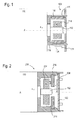
- Figure 1 shows a hysteresis brake 100 in combination with an electric motor 110.
- a shaft 112 in this case the drive shaft of the electric motor 110, extends in the axial direction A out of an end side of the electric motor 110.
- the shaft 112 preferably extends through the entire electric motor 110 and projects out at the other side of the electric motor 110, where said shaft 112 serves for example as a drive shaft for a device which brings about an automatic opening of a vehicle door, such as a tailgate of a luggage compartment (not shown).
- a magnet element 114 is fastened to the shaft 112 in such a way as to rotate together with said shaft 112.
- the magnet element 114 is a permanent magnet in the form of a magnet disc which is aligned perpendicular to the axial direction A, with diametrically running magnetization, as indicated by the poles N and S in Figure 1 .
- the number of magnet segments of the magnet element 114 is determined from the specific demands, and can be selected correspondingly by a person skilled in the art.
- An annular hysteresis element 116 is arranged in such a way as to annularly surround the magnet element 114 in the radial direction r.
- the spacing between the outer diameter of the magnet element 114 and the inner diameter of the hysteresis element 116 and the extents of the magnet element 114 and of the hysteresis element 116 in the radial direction r and in the axial direction A are selected here such that the magnetic field of the magnet element 114 penetrates the hysteresis element 116 with such an intensity as to ensure a sufficient braking action for the shaft 112.
- the hysteresis element 116 is composed for example of soft iron or an AlNiCo alloy. Other materials which are known for hysteresis elements may of course also be used.
- the hysteresis element 116 is fastened to a housing 118 which is in turn fixedly connected to the end side of the electric motor 110.
- the housing 118 may for example annularly surround the hysteresis element 116, or it is for example possible for only individual arms 120 to be formed in the axial direction A, to which arms 120 the hysteresis element 116 is fastened, for example by means of latching.
- a printed circuit board 122 Arranged at a small axial distance from the magnet element 114 and from the hysteresis element 116 is a printed circuit board 122 which is aligned perpendicularly with respect to the axial direction A and which is likewise fastened to the housing 118. At least one Hall sensor 124 is arranged on said printed circuit board 122. It is also possible for the electronic components required for the evaluation of the signal of the Hall sensor 124 to be provided on the printed circuit board 122.
- the Hall sensor 124 is situated at the level of the magnet element 114 and of the hysteresis element 116, such that said Hall sensor 124 can measure the alternating polarity of the magnetic field of the magnet element 114 when the shaft 112 rotates.
- the Hall sensor 124 is arranged on the printed circuit board 122 in such a way as to be situated, as viewed in the radial direction r, outside the housing 118 and above all outside the hysteresis element 116.
- the magnetic field of the magnet element 114 is therefore partially shielded from the Hall sensor 124 by the hysteresis element 116.
- FIG. 2 illustrates a second embodiment.
- the hysteresis brake 200 differs from the embodiment described immediately above merely in the arrangement of the magnet element, of the hysteresis element and of the Hall sensor. Identical or functionally equivalent components are therefore denoted by the reference symbols which have already been used.
- the magnet element 214 is embodied as a magnet disc which is placed directly onto the shaft 112 of the electric motor 110 and which rotates together with the latter.
- the hysteresis element 216 is embodied as an annular disc which is arranged at an axial distance a from the magnet element 214 and so as to be perpendicular with respect to the axial direction A, specifically, in this example, on that side of the magnet element 214 which faces away from the electric motor 110.
- the permanent magnet of the magnet element 214 has magnetization in the axial direction A, such that the magnetic field of the magnet element 214 penetrates the hysteresis element 216 effectively.
- the magnet element 214 has a plurality of zones of different polarity (indicated in Figure 2 ), such that a magnetic field with alternating polarity is generated at a location radially outwards from the shaft 112 when the magnet element 214 rotates.
- a Hall sensor 224 Arranged at a radial distance r 1 from the shaft 112, at the level both of the surface of the magnet element 214 and also of the hysteresis element 216, is a Hall sensor 224 which measures the magnetic field of the magnet element 214. As in the example described immediately above, said Hall sensor 224 is fastened to a printed circuit board 122 which may also support evaluating electronics.
- the housing 218 is designed so as to receive, and hold, both the hysteresis element 216 and also the printed circuit board 122 which is arranged perpendicular to the axial direction A.
- the Hall sensor 224 When the shaft 122 rotates, the Hall sensor 224 is exposed to a periodically varying magnetic field, since the zones of different polarity of the magnet element 124 move with respect to the Hall sensor 124. This results in a periodically varying signal which makes it possible, for example, to determine the number of rotations and the rotational speed of the shaft 112.
- hysteresis element 216 on the other side of the magnet element 214, in this case, in Figure 2 , between the electric motor 110 and the magnet element 214, if the Hall sensor 224 is designed for the field strengths which are provided by the magnet element 214 without shielding from the hysteresis element 216.
- the Hall sensor 324 is situated at an axial distance from the magnet element 114, while the hysteresis element 116 is arranged radially around the magnet element 114.
- the Hall sensor 324 is exposed to the full field strength of the magnet element 114. It would also be possible for the Hall sensor 324 to be arranged radially outside the hysteresis element 116 but at an axial distance both from the magnet element 114 and also from the hysteresis element 116.
- the Hall sensor 424 is situated radially outside the disc-shaped hysteresis element 216.
- the Hall sensor 424 may directly measure the magnetic field of the magnet element 214, or else that of the hysteresis element 216.
- the Hall sensor 424 is arranged approximately at the axial level of the hysteresis element 216, though could also be positioned at any desired location in the axial direction A, in particular at the level of the magnet element 214 or axially outside both the hysteresis element 216 and also the magnet element 214.
- the Hall sensor may use the magnetic field of the magnet element itself, or else the magnetic field caused by the magnetization of the hysteresis element, to detect the rotation of the shaft 112.
Landscapes
- Engineering & Computer Science (AREA)
- Power Engineering (AREA)
- Dynamo-Electric Clutches, Dynamo-Electric Brakes (AREA)
Priority Applications (1)
| Application Number | Priority Date | Filing Date | Title |
|---|---|---|---|
| EP08170086A EP2192675A1 (de) | 2008-11-27 | 2008-11-27 | Hysteresebremse |
Applications Claiming Priority (1)
| Application Number | Priority Date | Filing Date | Title |
|---|---|---|---|
| EP08170086A EP2192675A1 (de) | 2008-11-27 | 2008-11-27 | Hysteresebremse |
Publications (1)
| Publication Number | Publication Date |
|---|---|
| EP2192675A1 true EP2192675A1 (de) | 2010-06-02 |
Family
ID=40613103
Family Applications (1)
| Application Number | Title | Priority Date | Filing Date |
|---|---|---|---|
| EP08170086A Withdrawn EP2192675A1 (de) | 2008-11-27 | 2008-11-27 | Hysteresebremse |
Country Status (1)
| Country | Link |
|---|---|
| EP (1) | EP2192675A1 (de) |
Cited By (10)
| Publication number | Priority date | Publication date | Assignee | Title |
|---|---|---|---|---|
| WO2012007551A1 (fr) * | 2010-07-16 | 2012-01-19 | Valeo Sicherheitssysteme Gmbh | Dispositif d'actionnement motorisé d'ouvrant de véhicule automobile |
| CN104153673A (zh) * | 2014-08-29 | 2014-11-19 | 南京赛梵电气科技有限公司 | 一种基于永磁直线电机的电动平移门驱动装置 |
| EP2902578A3 (de) * | 2014-01-31 | 2015-11-25 | Aisin Seiki Kabushiki Kaisha | Widerstandserzeugungsvorrichtung für eine Antriebseinheit |
| DE102018100562A1 (de) | 2018-01-11 | 2019-07-11 | Stabilus Gmbh | Motorisiertes antriebssystem, verwendung des antriebssystems zur betätigung einer tür, herstellungsverfahren für ein antriebssystem |
| CN110957891A (zh) * | 2019-12-24 | 2020-04-03 | 北京青云航空仪表有限公司 | 一种高阻尼力矩密度磁滞阻尼器 |
| US10903713B2 (en) | 2015-12-25 | 2021-01-26 | Minebea Mitsumi Inc. | Inner-rotor motor |
| WO2023001727A1 (de) * | 2021-07-21 | 2023-01-26 | Brose Fahrzeugteile Se & Co. Kommanditgesellschaft, Bamberg | Antriebseinheit zum motorischen verstellen eines verschlusselements |
| DE102022100369B3 (de) | 2022-01-10 | 2023-04-27 | Stabilus Gmbh | Elektromotor zum Antrieb einer Fahrzeugklappe, Verwendung und Verfahren zur Herstellung des Elektromotors |
| US20240068290A1 (en) * | 2022-08-26 | 2024-02-29 | Nicholas Martin Klietsch | Eddy current braking devices for moving doors and other structures |
| WO2025077725A1 (zh) * | 2023-10-11 | 2025-04-17 | 宁波恒帅股份有限公司 | 一种集成信号采集器与磁滞器的电机 |
Citations (3)
| Publication number | Priority date | Publication date | Assignee | Title |
|---|---|---|---|---|
| US4107561A (en) * | 1974-10-09 | 1978-08-15 | U.S. Philips Corporation | Clutch apparatus for generating a pulse train |
| WO2005111383A1 (de) * | 2004-05-12 | 2005-11-24 | Daimlerchrysler Ag | Hysteresebremse, insbesondere für einen elektrischen nockenwellensteller |
| EP1940012A1 (de) | 2006-12-27 | 2008-07-02 | Valeo Sicherheitssysteme GmbH | Selbsttätigeverstellvorrichtung für eine Kraftfahrzeugtür |
-
2008
- 2008-11-27 EP EP08170086A patent/EP2192675A1/de not_active Withdrawn
Patent Citations (3)
| Publication number | Priority date | Publication date | Assignee | Title |
|---|---|---|---|---|
| US4107561A (en) * | 1974-10-09 | 1978-08-15 | U.S. Philips Corporation | Clutch apparatus for generating a pulse train |
| WO2005111383A1 (de) * | 2004-05-12 | 2005-11-24 | Daimlerchrysler Ag | Hysteresebremse, insbesondere für einen elektrischen nockenwellensteller |
| EP1940012A1 (de) | 2006-12-27 | 2008-07-02 | Valeo Sicherheitssysteme GmbH | Selbsttätigeverstellvorrichtung für eine Kraftfahrzeugtür |
Cited By (21)
| Publication number | Priority date | Publication date | Assignee | Title |
|---|---|---|---|---|
| WO2012007551A1 (fr) * | 2010-07-16 | 2012-01-19 | Valeo Sicherheitssysteme Gmbh | Dispositif d'actionnement motorisé d'ouvrant de véhicule automobile |
| CN103119235A (zh) * | 2010-07-16 | 2013-05-22 | 法雷奥安全系统有限责任公司 | 用于促动机动车辆的可运动面板的马达驱动装置 |
| EP2902578A3 (de) * | 2014-01-31 | 2015-11-25 | Aisin Seiki Kabushiki Kaisha | Widerstandserzeugungsvorrichtung für eine Antriebseinheit |
| US9461532B2 (en) | 2014-01-31 | 2016-10-04 | Aisin Seiki Kabushiki Kaisha | Resistance generating device for drive unit |
| CN104153673A (zh) * | 2014-08-29 | 2014-11-19 | 南京赛梵电气科技有限公司 | 一种基于永磁直线电机的电动平移门驱动装置 |
| CN104153673B (zh) * | 2014-08-29 | 2016-03-30 | 南京赛梵电气科技有限公司 | 一种基于永磁直线电机的电动平移门驱动装置 |
| US10903713B2 (en) | 2015-12-25 | 2021-01-26 | Minebea Mitsumi Inc. | Inner-rotor motor |
| US11211842B2 (en) | 2015-12-25 | 2021-12-28 | Minebea Mitsumi Inc. | Inner-rotor motor with urging structure |
| US11764637B2 (en) | 2015-12-25 | 2023-09-19 | Minebea Mitsumi Inc. | Inner-rotor motor |
| DE102018100562A1 (de) | 2018-01-11 | 2019-07-11 | Stabilus Gmbh | Motorisiertes antriebssystem, verwendung des antriebssystems zur betätigung einer tür, herstellungsverfahren für ein antriebssystem |
| WO2019138068A1 (de) | 2018-01-11 | 2019-07-18 | Stabilus Gmbh | Motorisiertes antriebssystem, verwendung des antriebssystems zur betätigung einer tür, herstellungsverfahren für ein antriebssystem |
| KR20200106059A (ko) * | 2018-01-11 | 2020-09-10 | 스테빌루스게엠베하 | 모터식 구동 시스템, 도어 작동을 위한 구동 시스템 사용 및 구동 시스템 생산 방법 |
| US11332969B2 (en) | 2018-01-11 | 2022-05-17 | Stabilus Gmbh | Motorized drive system, use of the drive system for actuating a door, and method for producing a drive system |
| EP3737817B1 (de) | 2018-01-11 | 2025-03-05 | STABILUS GmbH | Motorisiertes antriebssystem, verwendung des antriebssystems zur betätigung einer tür, herstellungsverfahren für ein antriebssystem |
| CN110957891A (zh) * | 2019-12-24 | 2020-04-03 | 北京青云航空仪表有限公司 | 一种高阻尼力矩密度磁滞阻尼器 |
| WO2023001727A1 (de) * | 2021-07-21 | 2023-01-26 | Brose Fahrzeugteile Se & Co. Kommanditgesellschaft, Bamberg | Antriebseinheit zum motorischen verstellen eines verschlusselements |
| DE102022100369B3 (de) | 2022-01-10 | 2023-04-27 | Stabilus Gmbh | Elektromotor zum Antrieb einer Fahrzeugklappe, Verwendung und Verfahren zur Herstellung des Elektromotors |
| EP4210206A1 (de) | 2022-01-10 | 2023-07-12 | STABILUS GmbH | Elektromotor zum antrieb einer fahrzeugklappe, verwendung und verfahren zur herstellung des elektromotors |
| US12483078B2 (en) | 2022-01-10 | 2025-11-25 | Stabilus Gmbh | Electric motor for driving a vehicle flap, use and method of manufacturing of the electric motor |
| US20240068290A1 (en) * | 2022-08-26 | 2024-02-29 | Nicholas Martin Klietsch | Eddy current braking devices for moving doors and other structures |
| WO2025077725A1 (zh) * | 2023-10-11 | 2025-04-17 | 宁波恒帅股份有限公司 | 一种集成信号采集器与磁滞器的电机 |
Similar Documents
| Publication | Publication Date | Title |
|---|---|---|
| US5969518A (en) | Antifriction mounting having a rotational-speed measuring device protected from contamination | |
| CN107209231B (zh) | 基于磁体的转角测量系统 | |
| CN107209026B (zh) | 基于磁体的转角测量系统 | |
| US6124710A (en) | Rotary magnetic encoder using hall effect for detecting revolution of a shaft | |
| US10998798B2 (en) | Drive assembly, in particular hydraulic assembly of an electronically slip-controllable vehicle brake system | |
| KR20040030057A (ko) | 속도 검출기를 구비한 기어 구동 유닛 | |
| US10466076B2 (en) | Sensor device having a torque sensor unit and an incremental sensor unit and motor vehicle having such a sensor device | |
| US11333527B2 (en) | Screening system for magnetic rotary-encoder sensor system | |
| US12320397B2 (en) | Magnetorheological braking device, in particular operating apparatus | |
| JP2007508988A (ja) | ディスクブレーキ | |
| US20220403897A1 (en) | Magnetorheological brake device, in particular an operating device | |
| JP2021530707A (ja) | 回転角度測定システム | |
| CN102072738A (zh) | 啮合编码器齿轮和传感器组件 | |
| EP2372153B1 (de) | Capteur de vitesse | |
| US20140103783A1 (en) | Drive system having a bearing tilt detection system, and electric or hybrid vehicle having the same | |
| KR940006597B1 (ko) | 전동장치 속도 감지기 | |
| CN108370202B (zh) | 在电机中的传感器装置 | |
| CN109774377A (zh) | 一种用于容纳轮速传感器的结构及用于车辆的驱动轴 | |
| JP2009186410A (ja) | 回転検出装置 | |
| JP2005069449A (ja) | センサ付軸受 | |
| CN216206421U (zh) | 转动检测装置及转动设备 | |
| JP3490826B2 (ja) | エンコーダ | |
| KR970066149A (ko) | 전자석을 이용한 브레이크장치 | |
| GB2332059A (en) | Instrument for measuring the speed of rotation of a motor vehicle wheel | |
| JPH04232471A (ja) | 回転する構造部分の回転数を検出する装置 |
Legal Events
| Date | Code | Title | Description |
|---|---|---|---|
| PUAI | Public reference made under article 153(3) epc to a published international application that has entered the european phase |
Free format text: ORIGINAL CODE: 0009012 |
|
| AK | Designated contracting states |
Kind code of ref document: A1 Designated state(s): AT BE BG CH CY CZ DE DK EE ES FI FR GB GR HR HU IE IS IT LI LT LU LV MC MT NL NO PL PT RO SE SI SK TR |
|
| AX | Request for extension of the european patent |
Extension state: AL BA MK RS |
|
| 17P | Request for examination filed |
Effective date: 20101202 |
|
| 17Q | First examination report despatched |
Effective date: 20101229 |
|
| AKX | Designation fees paid |
Designated state(s): AT BE BG CH CY CZ DE DK EE ES FI FR GB GR HR HU IE IS IT LI LT LU LV MC MT NL NO PL PT RO SE SI SK TR |
|
| STAA | Information on the status of an ep patent application or granted ep patent |
Free format text: STATUS: THE APPLICATION IS DEEMED TO BE WITHDRAWN |
|
| 18D | Application deemed to be withdrawn |
Effective date: 20110510 |