EP2193014B1 - Vorrichtung zur herstellung eines teils aus einem verbundmaterial mit einem entwässerungssystem und verfahren zur verwendung der selben - Google Patents
Vorrichtung zur herstellung eines teils aus einem verbundmaterial mit einem entwässerungssystem und verfahren zur verwendung der selben Download PDFInfo
- Publication number
- EP2193014B1 EP2193014B1 EP08839850A EP08839850A EP2193014B1 EP 2193014 B1 EP2193014 B1 EP 2193014B1 EP 08839850 A EP08839850 A EP 08839850A EP 08839850 A EP08839850 A EP 08839850A EP 2193014 B1 EP2193014 B1 EP 2193014B1
- Authority
- EP
- European Patent Office
- Prior art keywords
- composite material
- producing
- produced
- plate
- openings
- Prior art date
- Legal status (The legal status is an assumption and is not a legal conclusion. Google has not performed a legal analysis and makes no representation as to the accuracy of the status listed.)
- Active
Links
Images

Classifications
-
- B—PERFORMING OPERATIONS; TRANSPORTING
- B29—WORKING OF PLASTICS; WORKING OF SUBSTANCES IN A PLASTIC STATE IN GENERAL
- B29C—SHAPING OR JOINING OF PLASTICS; SHAPING OF MATERIAL IN A PLASTIC STATE, NOT OTHERWISE PROVIDED FOR; AFTER-TREATMENT OF THE SHAPED PRODUCTS, e.g. REPAIRING
- B29C70/00—Shaping composites, i.e. plastics material comprising reinforcements, fillers or preformed parts, e.g. inserts
- B29C70/04—Shaping composites, i.e. plastics material comprising reinforcements, fillers or preformed parts, e.g. inserts comprising reinforcements only, e.g. self-reinforcing plastics
- B29C70/28—Shaping operations therefor
- B29C70/54—Component parts, details or accessories; Auxiliary operations, e.g. feeding or storage of prepregs or SMC after impregnation or during ageing
- B29C70/546—Measures for feeding or distributing the matrix material in the reinforcing structure
-
- B—PERFORMING OPERATIONS; TRANSPORTING
- B29—WORKING OF PLASTICS; WORKING OF SUBSTANCES IN A PLASTIC STATE IN GENERAL
- B29C—SHAPING OR JOINING OF PLASTICS; SHAPING OF MATERIAL IN A PLASTIC STATE, NOT OTHERWISE PROVIDED FOR; AFTER-TREATMENT OF THE SHAPED PRODUCTS, e.g. REPAIRING
- B29C43/00—Compression moulding, i.e. applying external pressure to flow the moulding material; Apparatus therefor
- B29C43/32—Component parts, details or accessories; Auxiliary operations
- B29C43/36—Moulds for making articles of definite length, i.e. discrete articles
- B29C43/3642—Bags, bleeder sheets or cauls for isostatic pressing
-
- B—PERFORMING OPERATIONS; TRANSPORTING
- B29—WORKING OF PLASTICS; WORKING OF SUBSTANCES IN A PLASTIC STATE IN GENERAL
- B29C—SHAPING OR JOINING OF PLASTICS; SHAPING OF MATERIAL IN A PLASTIC STATE, NOT OTHERWISE PROVIDED FOR; AFTER-TREATMENT OF THE SHAPED PRODUCTS, e.g. REPAIRING
- B29C70/00—Shaping composites, i.e. plastics material comprising reinforcements, fillers or preformed parts, e.g. inserts
- B29C70/04—Shaping composites, i.e. plastics material comprising reinforcements, fillers or preformed parts, e.g. inserts comprising reinforcements only, e.g. self-reinforcing plastics
- B29C70/28—Shaping operations therefor
- B29C70/40—Shaping or impregnating by compression not applied
- B29C70/42—Shaping or impregnating by compression not applied for producing articles of definite length, i.e. discrete articles
- B29C70/44—Shaping or impregnating by compression not applied for producing articles of definite length, i.e. discrete articles using isostatic pressure, e.g. pressure difference-moulding, vacuum bag-moulding, autoclave-moulding or expanding rubber-moulding
- B29C70/443—Shaping or impregnating by compression not applied for producing articles of definite length, i.e. discrete articles using isostatic pressure, e.g. pressure difference-moulding, vacuum bag-moulding, autoclave-moulding or expanding rubber-moulding and impregnating by vacuum or injection
-
- B—PERFORMING OPERATIONS; TRANSPORTING
- B29—WORKING OF PLASTICS; WORKING OF SUBSTANCES IN A PLASTIC STATE IN GENERAL
- B29C—SHAPING OR JOINING OF PLASTICS; SHAPING OF MATERIAL IN A PLASTIC STATE, NOT OTHERWISE PROVIDED FOR; AFTER-TREATMENT OF THE SHAPED PRODUCTS, e.g. REPAIRING
- B29C43/00—Compression moulding, i.e. applying external pressure to flow the moulding material; Apparatus therefor
- B29C43/32—Component parts, details or accessories; Auxiliary operations
- B29C43/36—Moulds for making articles of definite length, i.e. discrete articles
- B29C43/3642—Bags, bleeder sheets or cauls for isostatic pressing
- B29C2043/3644—Vacuum bags; Details thereof, e.g. fixing or clamping
Definitions
- the present invention relates to a device for manufacturing a composite material part, said device incorporating a drainage system and being more particularly intended for the manufacture of panels of complex shape, in particular with double curvature.
- Aircraft construction tends to use composite materials for the realization of parts of an aircraft, including panels forming the outer skin of the fuselage, to reduce the weight on board.
- the outer surface of the fuselage In contact with large aerodynamic flows, the outer surface of the fuselage must have a surface state giving the aircraft the best aerodynamic characteristics. Indeed, the surface defects cause an increase in the drag and therefore an increase in the energy consumption of the device.
- the outer surface of the fuselage in contact with the air include no porosity.
- the parts made of composite material comprise a fiber reinforced resin matrix.
- the fibers are in the form of one or more ply (s) woven (s) or not, prepreg (s) of thermosetting resin.
- the fibers may not be prepreg. In this case, at least one resin film is used.
- the present invention more particularly relates to the procedure of using a compaction bladder to exert the pressure and an autoclave for the polymerization.
- a procedure is used for the method of manufacturing an aircraft fuselage made of composite material described in the document FR-2894869 .
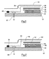
- FIG. 1 there is shown a device of the prior art.
- the composite material part attached to a mold 12 and covered by a compaction bladder 14 is found in 10.
- Drainage means, in the form of a draining fabric 16, are interposed between the part 10 and the bladder 14.
- a non-perforated film 18 allowing the gases to pass through but retaining the resin during the polymerization, is interposed between the part 10 and the draining fabric 16.
- the device comprises a seal 20, provided for sealing, interposed between the mold 12 and the bladder 14, at the periphery of the part 10 as well as means 22 for ensuring the depression and / or the evacuation of the gases.
- a film 24 to be delaminated, in direct contact with the part, favoring the removal of the various layers added to the part at the end of the process.
- drainage means for example draining glass fabric 26, may be provided.
- a plate 28 also called a shaping plate, can be placed between the draining fabric 16 and the bladder 14.
- This shaping plate 28 also to smooth the surface and to homogenize the distribution of pressure forces exerted by the bladder on the surface of the part 10. Also, this shaping plate is smooth and has no roughness to ensure the smoothing function.
- the installation of the drainage fabric is problematic, the fabric having a flexible structure likely to wrinkle. Indeed, if the drainage fabric is deposited with folds, they are duplicated on the outer surface of the composite material panel which is thus marked. These marks are not acceptable because they lead to increased drag.
- the draining fabric can not adapt, without crease, to the outer surface of the panel of composite material and necessarily comprises folds.
- One solution is then not to use a single piece of draining fabric capable of covering the entire panel but a plurality of parts to obtain a three-dimensional shape adapted to the shape of the panel.
- junction areas between the pieces tend to mark the outer surface.
- the present invention aims at overcoming the drawbacks of the prior art by proposing a device for producing a part made of composite material integrating a drainage system that simplifies its installation and limits the risk of appearance of marks on the surface. surface of the part made, likely to degrade the aerodynamic characteristics of said part.
- the subject of the invention is a device for producing a composite material part intended to be in contact with aerodynamic flows, in particular a part of the fuselage, according to claim 1 and a method according to claim 8.
- FIG. 3 and 4 there is shown a device for producing a composite material part 30, more particularly adapted to produce a large panel may form a part of the fuselage of an aircraft.
- a device for producing a composite material part 30, more particularly adapted to produce a large panel may form a part of the fuselage of an aircraft.
- the composite material part comprises a fiber reinforced resin matrix.
- the piece of composite material is obtained from one or more ply (s) woven (s) or not, prepreg (s) of thermosetting resin or not.
- the fibers may not be pre-impregnated, at least one resin film then being required to form the matrix.
- the device comprises at least one mold 32 on which are reported the various elements constituting the part to be produced.
- This mold has shapes adapted according to the desired shape of the part 30.
- the mold 32 is in the form of a mandrel whose outer surface on which are draped the folds of the part to be made has shapes adapted to those desired from the inner surface of the composite material part.
- this mold 32 can be made in one piece or from several moving parts or not between them.
- the mold may consist at least partially of the internal frame of the fuselage as described in document FR-2894869 .
- the mold 32 is not more detailed because it is known to those skilled in the art and can take different configurations depending on the parts to achieve.
- the device comprises compression means.
- these compression means comprise a compacting bladder 34 which covers the elements of the part to be produced, sealing means 36 at the periphery of the elements of the part to be made. realize providing sealing between the mold 32 and compacting bladder 34 and means 38 for generating a vacuum in the cavity 40 defined by the mold 32 and the bladder 34 in which are arranged the elements of the part to be produced.
- the device comprises a drainage system.
- the drainage system comprises at least one plate 42 having a plurality of orifices 44, as illustrated in detail in FIG. figure 3 said plate 42 being shaped according to the outer surface of the part to be produced.
- the same element (the plate 42) is used to provide drainage and conformage functions.
- This shaping plate and drainage 42 can be made from different materials. Thus, it can be metallic or composite material. According to one embodiment, the shaping and drainage plate 42 is made of composite material and has a thickness less than approximately 5 mm. Given the ratio between its thickness and its area, the shaping plate and drainage 42 may be more or less flexible. However, it is not flexible in the manner of a fabric likely to wrinkle. Insofar as it can not wrinkle, the establishment of the shaping plate and drainage 42 is simple and fast, which leads to reduce the implementation time. In addition, the fact that it is shaped according to the outer surface of the part to be made simplifies its implementation.
- the shaping and drainage plate 42 can be reused for several firings unlike the draining fabrics of the prior art, which allows to obtain a gain in terms of costs and waste.
- the drainage function is provided by the plurality of orifices 44 which enable the gases to be captured on one side of the plate and to evacuate them on the other side of the plate.
- the orifices 44 have shapes and / or an arrangement adapted to limit the degradation of the aerodynamic characteristics of said part to be produced.
- the orifices may have different geometries.
- the orifices 44 have a substantially circular shape. This form is simple to achieve and provides a good compromise between the drainage function and the fact of not producing marks on the outer surface of the part to achieve, likely to degrade the aerodynamic characteristics of said piece. However, other forms are conceivable.
- the orifices 44 have a diameter and a density adapted to satisfactorily provide the drainage function without, however, producing marks on the outer surface of the part to be produced, capable of degrading the aerodynamic characteristics of said part.
- the orifices have a section less than 5 mm 2 .
- the orifices When they are circular, the orifices have a diameter of less than 1 mm in order not to produce any marking likely to degrade the aerodynamic characteristics of said part.
- the pitch between two orifices is of the order of 50 mm.
- the orifices are arranged along lines arranged in the direction of the flow of the aerodynamic flows, staggered from one line to another, the orifices of the same line being spaced apart from each other by a distance of the order of 50 mm.
- the open surface area namely the ratio between the sum of the surfaces of the orifices on the surface of the plate is of the order of 1256 mm 2 / m 2 to obtain a good compromise between the drainage function and the fact of not producing marks on the outer surface of the plate. piece to achieve, likely to degrade the aerodynamic characteristics of said piece.
- the shaping and drainage plate 42 may be made in one piece or from several pieces arranged end to end.
- the shaping and drainage plate 42 comprises four parts, an upper part 42.1, two lateral parts 42.2, 42.3 and a lower part 44.4.
- the device comprises means 26 for discharging the gases captured by the drainage system.
- these evacuation means 46 comprise on the one hand a tissue, for example a glass cloth, interposed between the compaction bladder 34 and the shaping and drainage plate 42, and on the other hand minus an exhaust pipe advantageously for sucking the gases.
- a non-perforated liquid-tight but gas-permeable film 48 is interposed between the workpiece 30 and the shaping and drainage plate 42.
- a film 50 to be delaminated is provided in direct contact with the part, favoring the removal of the various layers reported on the part at the end of the process.
Landscapes
- Engineering & Computer Science (AREA)
- Mechanical Engineering (AREA)
- Chemical & Material Sciences (AREA)
- Composite Materials (AREA)
- Casting Or Compression Moulding Of Plastics Or The Like (AREA)
Claims (8)
- Vorrichtung zur Herstellung eines Teils aus Verbundwerkstoff, das dazu bestimmt ist, mit aerodynamischen Strömungen in Kontakt zu sein, insbesondere eines Teils des Flugzeugrumpfes, wobei die Vorrichtung wenigstens eine Form (32), Mittel (34, 36, 38) zum Verdichten des herzustellenden Teils sowie ein System zum Drainieren der von dem herzustellenden Teil stammenden Gase, das wenigstens eine Platte (42) mit einer Vielzahl von Öffnungen (44) aufweist, umfasst, dadurch gekennzeichnet, dass die Formen und/oder die anordnung der Öffnungen die Verschlechterung der aerodynamischen Eigenschaften des herzustellenden Teils begrenzen und dass die öffnungen (44) einen Querschnitt von weniger als 5 mm2 aufweisen und in Reihen, welche in Strömungsrichtung der aerodynamischen Ströme angeordnet sind, mit einem Versatz von einer Reihe zur nächsten, wobei die öffnungen einer gleichen Reihe um einen Abstand in der Größenordnung von 50 mm voneinander beabstandet sind.
- Vorrichtung zur Herstellung eines Teils aus Verbundwerkstoff nach Anspruch 1, dadurch gekennzeichnet, dass die Öffnungen (44) im Wesentlichen kreisförmig sind.
- Vorrichtung zur Herstellung eines Teils aus Verbundwerkstoff nach Anspruch 2, dadurch gekennzeichnet, dass die Öffnungen (44) einen Durchmesser von weniger als 1 mm aufweisen.
- Vorrichtung zur Herstellung eines Teils aus Verbundwerkstoff nach einem der Ansprüche 1 bis 3, dadurch gekennzeichnet, dass die wenigstens eine Platte (42) entsprechend der Außenfläche des herzustellenden Teils gestaltet ist.
- Vorrichtung zur Herstellung eines Teils aus Verbundwerkstoff nach einem der Ansprüche 1 bis 4, dadurch gekennzeichnet, dass sie Mittel (26) zum Ableiten der durch das Drainagesystem aufgefangenen Gase umfasst.
- Vorrichtung zur Herstellung eines Teils aus Verbundwerkstoff nach Anspruch 5, wobei die Vorrichtung eine Verdichtungsblase (34) umfasst, dadurch gekennzeichnet, dass die Ableitungsmittel (46) einerseits ein zwischen der Verdichtungsblase (34) und der Platte (42) eingefügtes Gewebe und andererseits wenigstens eine Austrittsleitung umfassen.
- Vorrichtung zur Herstellung eines Teils aus Verbundwerkstoff nach einem der Ansprüche 1 bis 6, dadurch gekennzeichnet, dass sie einen flüssigkeitsdichten, aber gasdurchlässigen, nicht perforierten Film (48) umfasst, der zwischen dem herzustellenden Teil (30) und der Platte (42) eingefügt ist.
- Verfahren zur Herstellung eines Teils aus Verbundwerkstoff, dessen eine Fläche dazu bestimmt ist, mit aerodynamischen Strömungen in Kontakt zu sein, insbesondere eines Teils des Flugzeugrumpfes, wobei das Verfahren darin besteht, die Lagen des Teils zwischen wenigstens einer Form (32) und Mitteln zum Verdichten (34, 36, 38), umfassend ein Drainagesystem, das wenigstens eine Platte (42) mit einer Vielzahl von Öffnungen (44) aufweist, um den Durchgang der von dem herzustellenden Teil stammenden Gase zu ermöglichen, zu drapieren, dadurch gekennzeichnet, dass es darin besteht, eine Platte zu verwenden, deren Öffnungen Formen und/oder eine Anordnung aufweisen, welche die Verschlechterung der aerodynamischen Eigenschaften des herzustellenden Teils begrenzen, sowie einen Querschnitt von weniger als 5 mm2 aufweisen und in Reihen, welche in Strömungsrichtung der aerodynamischen Ströme angeordnet sind, mit einem Versatz von einer Reihe zur nächsten, wobei die Öffnungen einer gleichen Reihe um einen Abstand in der Größenordnung von 50 mm voneinander beabstandet sind.
Applications Claiming Priority (2)
| Application Number | Priority Date | Filing Date | Title |
|---|---|---|---|
| FR0757795A FR2921295A1 (fr) | 2007-09-24 | 2007-09-24 | Dispositif pour la fabrication d'une piece en materiau composite integrant un systeme de drainage |
| PCT/FR2008/051696 WO2009050362A2 (fr) | 2007-09-24 | 2008-09-23 | Dispositif pour la fabrication d'une piece en materiau composite integrant un systeme de drainage |
Publications (2)
| Publication Number | Publication Date |
|---|---|
| EP2193014A2 EP2193014A2 (de) | 2010-06-09 |
| EP2193014B1 true EP2193014B1 (de) | 2011-07-13 |
Family
ID=39432189
Family Applications (1)
| Application Number | Title | Priority Date | Filing Date |
|---|---|---|---|
| EP08839850A Active EP2193014B1 (de) | 2007-09-24 | 2008-09-23 | Vorrichtung zur herstellung eines teils aus einem verbundmaterial mit einem entwässerungssystem und verfahren zur verwendung der selben |
Country Status (5)
| Country | Link |
|---|---|
| US (1) | US8784092B2 (de) |
| EP (1) | EP2193014B1 (de) |
| AT (1) | ATE516131T1 (de) |
| FR (1) | FR2921295A1 (de) |
| WO (1) | WO2009050362A2 (de) |
Families Citing this family (5)
| Publication number | Priority date | Publication date | Assignee | Title |
|---|---|---|---|---|
| FR2948600B1 (fr) * | 2009-07-28 | 2011-10-07 | Airbus Operations Sas | Procede de fabrication d'une piece d'aeronef par infusion de resine |
| FR2987307B1 (fr) * | 2012-02-29 | 2017-02-10 | Daher Aerospace | Procede et dispositif pour le compactage et la consolidation d'un panneau composite de forte epaisseur a matrice thermoplastique |
| DE102015225467B4 (de) * | 2015-12-16 | 2019-12-19 | Airbus Defence and Space GmbH | Beschichtetes Verbundbauteil und Verfahren zum Herstellen eines beschichteten Verbundbauteils |
| FR3105075B1 (fr) | 2019-12-19 | 2022-02-11 | Stelia Aerospace | Dispositif de moulage drainant d’un système de fabrication de pièces en matériau composite |
| CN111619140A (zh) * | 2020-04-17 | 2020-09-04 | 重庆江东汽车零部件有限责任公司 | 一种真空灌注货箱底板工艺 |
Family Cites Families (64)
| Publication number | Priority date | Publication date | Assignee | Title |
|---|---|---|---|---|
| US3146148A (en) * | 1957-11-08 | 1964-08-25 | Gen Dynamics Corp | Apparatus for fabricating composite structures |
| US4132755A (en) * | 1977-07-22 | 1979-01-02 | Jay Johnson | Process for manufacturing resin-impregnated, reinforced articles without the presence of resin fumes |
| US4357193A (en) * | 1979-05-21 | 1982-11-02 | Rockwell International Corporation | Method of fabricating a composite structure |
| US4292356A (en) * | 1979-07-06 | 1981-09-29 | Rohr Industries, Inc. | Method of manufacturing of honeycomb noise attenuation structure and the structure resulting from the method |
| US4312829A (en) * | 1979-12-10 | 1982-01-26 | Fourcher Fredric J | Molding method |
| US4548859A (en) * | 1984-10-12 | 1985-10-22 | The Boeing Company | Breather material and method of coating fabric with silicone rubber |
| US4622091A (en) * | 1984-11-29 | 1986-11-11 | The Boeing Company | Resin film infusion process and apparatus |
| US4676853A (en) * | 1985-08-30 | 1987-06-30 | The United States Of America As Represented By The Administrator Of The National Aeronautics And Space Administration | Method of making a flexible diaphragm |
| US5123985A (en) * | 1986-09-02 | 1992-06-23 | Patricia Evans | Vacuum bagging apparatus and method including a thermoplastic elastomer film vacuum bag |
| US4869770A (en) * | 1987-12-03 | 1989-09-26 | The Boeing Company | Method and apparatus for laminating composite materials |
| US4983345A (en) * | 1987-12-28 | 1991-01-08 | United Technologies Corporation | Method of high temperature molding using a thermal barrier |
| US4902215A (en) * | 1988-06-08 | 1990-02-20 | Seemann Iii William H | Plastic transfer molding techniques for the production of fiber reinforced plastic structures |
| US4975311A (en) * | 1988-12-20 | 1990-12-04 | Itt Corporation | Vacuum lamination station |
| US4942013A (en) * | 1989-03-27 | 1990-07-17 | Mcdonnell Douglas Corporation | Vacuum resin impregnation process |
| US5052906A (en) * | 1989-03-30 | 1991-10-01 | Seemann Composite Systems, Inc. | Plastic transfer molding apparatus for the production of fiber reinforced plastic structures |
| US5023987A (en) * | 1989-08-28 | 1991-06-18 | The Boeing Company | Strato streak flush patch |
| US5009687A (en) * | 1989-10-02 | 1991-04-23 | United Technologies Corporation | Method of molding a composite article using softened glass as a pressure transmitting medium |
| US5242651A (en) * | 1990-07-25 | 1993-09-07 | Vought Aircraft Company | Pressure balanced processing of composite structures |
| US5116216A (en) * | 1991-02-28 | 1992-05-26 | The United States Of America As Represented By The Secretary Of The Navy | Apparatus for preparing thermoplastic composites |
| US5464337A (en) * | 1991-03-27 | 1995-11-07 | The Charles Stark Draper Laboratories | Resin transfer molding system |
| US5106568A (en) * | 1991-11-15 | 1992-04-21 | Mcdonnell Douglas Corporation | Method and apparatus for vacuum bag molding of composite materials |
| US5322665A (en) * | 1992-04-15 | 1994-06-21 | The Charles Stark Draper Laboratories, Inc. | Disposable self contained cartridge or resin transfer molding and resin transfer molding method |
| US5302107A (en) * | 1992-06-08 | 1994-04-12 | Airtech International Inc. | Apparatus for forming shaped parts of thermosetting resins or other materials |
| US5439635A (en) * | 1993-02-18 | 1995-08-08 | Scrimp Systems, Llc | Unitary vacuum bag for forming fiber reinforced composite articles and process for making same |
| US5565162A (en) * | 1994-09-30 | 1996-10-15 | Composite Manufacturing & Research Inc. | Method for manufacturing a fiber reinforced composite article |
| AU2584095A (en) * | 1995-01-27 | 1996-08-14 | Sikorsky Aircraft Corporation | Method for making honeycomb core composite articles |
| US6406659B1 (en) * | 1995-03-28 | 2002-06-18 | Eric Lang | Composite molding method and apparatus |
| US5576030A (en) * | 1995-10-02 | 1996-11-19 | Lockheed Corporation | Apparatus for fabricating composite parts |
| US6013361A (en) * | 1995-10-31 | 2000-01-11 | Lockheed Martin Corporation | High performance structural laminate composite material for use to 1000° F and above, apparatus for and method of manufacturing same, and articles made with same |
| US6203749B1 (en) * | 1996-02-15 | 2001-03-20 | David Loving | Process for fiberglass molding using a vacuum |
| US6508974B1 (en) * | 1996-02-15 | 2003-01-21 | David Loving | Process for fiberglass molding using a vacuum |
| US20040017020A1 (en) * | 2002-07-26 | 2004-01-29 | David Loving | Process for fiberglass molding using a vacuum |
| AU6304598A (en) * | 1997-02-27 | 1998-09-18 | Advanced Composites Group Ltd. | Improvements in or relating to moulding methods and moulded articles |
| US5863452A (en) * | 1997-04-17 | 1999-01-26 | Northrop Grumman Corporation | Isostatic pressure resin transfer molding |
| US5939013A (en) * | 1997-08-25 | 1999-08-17 | Florida State University | Process and apparatus for the production of high strength polymer composite structures |
| US5968445A (en) * | 1998-01-05 | 1999-10-19 | The Boeing Company | Method and apparatus for curing large composite panels |
| US6039832A (en) * | 1998-02-27 | 2000-03-21 | The Boeing Company | Thermoplastic titanium honeycomb panel |
| WO2000018555A1 (en) * | 1998-10-01 | 2000-04-06 | Airtech International, Inc. | Method of molding or curing a resin material at high temperatures using a multilayer release film |
| DE19853709C1 (de) * | 1998-11-20 | 2000-02-10 | Deutsch Zentr Luft & Raumfahrt | Vorrichtung und Verfahren zur Herstellung von faserverstärkten Kunststoffen bzw. Kunststoffbauteilen nach einem modifizierten RTM-Verfahren |
| US6090335A (en) * | 1999-01-08 | 2000-07-18 | Northrop Grumman Corporation | Process of forming fiber reinforced composite articles using an insitu cured resin infusion port |
| US6555045B2 (en) * | 1999-01-11 | 2003-04-29 | Northrop Grumman Corporation | Grooved mold apparatus and process for forming fiber reinforced composite structures |
| US6656411B1 (en) * | 1999-01-11 | 2003-12-02 | Northrop Grumman Corporation | Grooved core pattern for optimum resin distribution |
| DE10013409C1 (de) * | 2000-03-17 | 2000-11-23 | Daimler Chrysler Ag | Verfahren und Vorrichtung zur Herstellung von faserverstärkten Bauteilen mittels eines Injektionsverfahrens |
| US6818159B2 (en) * | 2000-03-17 | 2004-11-16 | Deutsches Zentrum Fuer Luft-Und Raumfahrt E.V. | Process for the production of a composite consisting of a fiber reinforced material |
| US6385836B1 (en) * | 2000-06-30 | 2002-05-14 | Lockheed Martin Corporation | Method for composite material repair |
| US6586054B2 (en) * | 2001-04-24 | 2003-07-01 | The United States Of America As Represented By The Secretary Of The Army | Apparatus and method for selectively distributing and controlling a means for impregnation of fibrous articles |
| US6565792B2 (en) * | 2001-05-11 | 2003-05-20 | Hardcore Composites | Apparatus and method for use in molding a composite structure |
| US6630095B2 (en) * | 2001-08-01 | 2003-10-07 | Lockheed Martin Corporation | Method for making composite structures |
| DE10156123B4 (de) * | 2001-11-16 | 2006-07-27 | Eads Deutschland Gmbh | Verfahren und Vorrichtung zur Herstellung von faserverstärkten Kunststoffbauteilen |
| US6739861B2 (en) * | 2001-11-26 | 2004-05-25 | Sikorsky Aircraft Corporation | High pressure co-cure of lightweight core composite article utilizing a core having a plurality of protruding pins |
| DE10160956A1 (de) * | 2001-12-12 | 2003-07-10 | Fibertex As Aalborg | Vlies und Verfahren zur Herstellung von glas- bzw. kohlefaserverstärkten Kunststoffen |
| US7204951B2 (en) * | 2002-07-30 | 2007-04-17 | Rocky Mountain Composites, Inc. | Method of assembling a single piece co-cured structure |
| US6851945B2 (en) * | 2002-12-11 | 2005-02-08 | Northrop Grumman Corporation | Seal-less reusable vacuum bag |
| US7112299B2 (en) * | 2003-07-09 | 2006-09-26 | Michael Merrick | Systems and methods for fabricating composite fiberglass laminate articles |
| US7189345B2 (en) * | 2003-08-13 | 2007-03-13 | The Boeing Company | Method for vacuum assisted resin transfer molding |
| US20050048260A1 (en) * | 2003-08-27 | 2005-03-03 | The Boeing Company | Method and apparatus for fabricating a laminated fiber metal composite |
| US7029267B2 (en) * | 2003-10-23 | 2006-04-18 | Saint- Gobain Technical Fabrics Canada, Ltd | Reusable vacuum bag and methods of its use |
| EP1687131B1 (de) * | 2003-11-27 | 2007-04-25 | BAE Systems PLC | Entlüftungsfolie für verbundwerkstoffaushärtung und anordnungsverfahren dafür |
| US7160498B2 (en) * | 2004-03-08 | 2007-01-09 | Tracker Marine, L.L.C. | Closed molding tool |
| US7186367B2 (en) * | 2004-05-13 | 2007-03-06 | The United States Of America As Represented By The Administrator Of The National Aeronautics And Space Administration | Double vacuum bag process for resin matrix composite manufacturing |
| US7306450B2 (en) * | 2004-09-29 | 2007-12-11 | The Boeing Company | Apparatuses, systems, and methods for manufacturing composite parts |
| FR2879498B1 (fr) * | 2004-12-16 | 2009-01-30 | Snecma Propulsion Solide Sa | Densification de structures fibreuses par rtm pour la realisation de pieces en materiau composite |
| FR2894869B1 (fr) | 2005-12-20 | 2009-10-09 | Airbus France Sas | Procede de fabrication d'un fuselage d'aeronef en materiau composite |
| US7595112B1 (en) * | 2006-07-31 | 2009-09-29 | The United States Of America As Represented By The Administrator Of The National Aeronautics And Space Administration | Resin infusion of layered metal/composite hybrid and resulting metal/composite hybrid laminate |
-
2007
- 2007-09-24 FR FR0757795A patent/FR2921295A1/fr not_active Withdrawn
-
2008
- 2008-09-23 WO PCT/FR2008/051696 patent/WO2009050362A2/fr not_active Ceased
- 2008-09-23 AT AT08839850T patent/ATE516131T1/de not_active IP Right Cessation
- 2008-09-23 US US12/678,158 patent/US8784092B2/en active Active
- 2008-09-23 EP EP08839850A patent/EP2193014B1/de active Active
Also Published As
| Publication number | Publication date |
|---|---|
| FR2921295A1 (fr) | 2009-03-27 |
| ATE516131T1 (de) | 2011-07-15 |
| EP2193014A2 (de) | 2010-06-09 |
| WO2009050362A3 (fr) | 2009-07-23 |
| US8784092B2 (en) | 2014-07-22 |
| US20100260884A1 (en) | 2010-10-14 |
| WO2009050362A2 (fr) | 2009-04-23 |
Similar Documents
| Publication | Publication Date | Title |
|---|---|---|
| CA2738745C (fr) | Procede de fabrication d'une piece en materiau composite avec une forme concave, notamment une section en u et dispositif pour sa mise en oeuvre | |
| EP2064050B1 (de) | Verfahren zur herstellung einer aus einem thermoplastischen komposit hergestellten platte | |
| EP2326486B1 (de) | Verfahren zur herstellung einer aus einem verbundmaterial hergestellten komponente und zugehörige vorrichtung | |
| CA2346311C (fr) | Procede de fabrication d'un panneau en materiau composite a bandes raidisseurs et panneau ainsi obtenu | |
| EP3916717B1 (de) | Schalldämmende wabenstruktur mit einer membran, die mit einem rohr versehen ist, das für die verarbeitung verschiedener akustischer frequenzen konfiguriert ist, verfahren zur herstellung einer solchen schalldämmenden wabenstruktur und entsprechendes werkzeug | |
| BE1017910A3 (fr) | Procede de fabrication d'un panneau comprenant au moins un corps en nid-d'abeilles et une premiere peau realisee en materiau composite. | |
| CA2930813A1 (fr) | Procede d'impregnation d'une preforme fibreuse et dispositif pour la mise en oeuvre de ce procede | |
| FR2928293A1 (fr) | Procede de fabrication d'un produit composite multi axial plan et produit obtenu par ce procede | |
| CA2925836C (fr) | Structure fibreuse avec regroupement des flottes | |
| FR2922152A1 (fr) | Structure a ame alveolaire pour panneau acoustique | |
| EP2385894A1 (de) | Verfahren zur herstellung einer schalldämpfenden platte, insbesondere für die aeronautik | |
| EP2193014A2 (de) | Vorrichtung zur herstellung eines teils aus einem verbundmaterial mit einem entwässerungssystem | |
| FR2995244A1 (fr) | Procede de realisation d'un profile en materiau composite presentant un angle rentrant a partir d'un empilage de couches de fibres | |
| WO2020043746A1 (fr) | Procédé de fabrication d'une préforme composite pour la fabrication d'un panneau composite à géométrie à double courbure | |
| EP3253556B1 (de) | Verfahren zur herstellung einer verkleidung und schallschutztafel für ein kraftfahrzeug | |
| FR2936442A1 (fr) | Dispositif pour la fabrication d'une piece en materiau composite de forme complexe. | |
| FR2903342A1 (fr) | Dispositif thermodurcissable ou thermoplastique pour la fabrication de tuyauterie de conditionnement d'air | |
| EP3645256B1 (de) | Verbundmaterial mit vorimprägnierten gewebten fasern | |
| FR2923748A1 (fr) | Procede de fabrication d'une structure fibreuse en nid d'abeilles. | |
| EP2237944A2 (de) | Vorrichtung zur herstellung eines teils aus einem verbundstoff mit glättungsplatten mit gleitverbindungen und verfahren zur herstellung von glättungsplatten mit gleitverbindungen | |
| WO2010089464A1 (fr) | Noyau pour realiser un raidisseur dans un panneau composite | |
| WO2018227309A1 (fr) | Procede de fabrication d' un panneau composite | |
| FR2983429A1 (fr) | Procede de fabrication d'une piece en materiau composite comportant au moins un rayon de courbure | |
| FR3061070A1 (fr) | Procede de realisation d’un panneau auto raidi en materiaux composites et panneau obtenu par ledit procede | |
| EP3842219B1 (de) | Verfahren zur herstellung eines teils aus zwei werkstoffen und nach diesem verfahren hergestelltes teil aus zwei werkstoffen |
Legal Events
| Date | Code | Title | Description |
|---|---|---|---|
| PUAI | Public reference made under article 153(3) epc to a published international application that has entered the european phase |
Free format text: ORIGINAL CODE: 0009012 |
|
| 17P | Request for examination filed |
Effective date: 20100319 |
|
| AK | Designated contracting states |
Kind code of ref document: A2 Designated state(s): AT BE BG CH CY CZ DE DK EE ES FI FR GB GR HR HU IE IS IT LI LT LU LV MC MT NL NO PL PT RO SE SI SK TR |
|
| AX | Request for extension of the european patent |
Extension state: AL BA MK RS |
|
| 17Q | First examination report despatched |
Effective date: 20100830 |
|
| GRAP | Despatch of communication of intention to grant a patent |
Free format text: ORIGINAL CODE: EPIDOSNIGR1 |
|
| RTI1 | Title (correction) |
Free format text: DEVICE FOR PRODUCING A PART FROM COMPOSITE MATERIAL, INCLUDING A DRAINAGE SYSTEM AND PROCESS USING THE SAME |
|
| GRAS | Grant fee paid |
Free format text: ORIGINAL CODE: EPIDOSNIGR3 |
|
| GRAA | (expected) grant |
Free format text: ORIGINAL CODE: 0009210 |
|
| AK | Designated contracting states |
Kind code of ref document: B1 Designated state(s): AT BE BG CH CY CZ DE DK EE ES FI FR GB GR HR HU IE IS IT LI LT LU LV MC MT NL NO PL PT RO SE SI SK TR |
|
| REG | Reference to a national code |
Ref country code: GB Ref legal event code: FG4D Free format text: NOT ENGLISH |
|
| REG | Reference to a national code |
Ref country code: CH Ref legal event code: EP |
|
| REG | Reference to a national code |
Ref country code: IE Ref legal event code: FG4D Free format text: LANGUAGE OF EP DOCUMENT: FRENCH |
|
| REG | Reference to a national code |
Ref country code: DE Ref legal event code: R096 Ref document number: 602008008281 Country of ref document: DE Effective date: 20110908 |
|
| REG | Reference to a national code |
Ref country code: NL Ref legal event code: VDEP Effective date: 20110713 |
|
| REG | Reference to a national code |
Ref country code: AT Ref legal event code: MK05 Ref document number: 516131 Country of ref document: AT Kind code of ref document: T Effective date: 20110713 |
|
| PG25 | Lapsed in a contracting state [announced via postgrant information from national office to epo] |
Ref country code: SE Free format text: LAPSE BECAUSE OF FAILURE TO SUBMIT A TRANSLATION OF THE DESCRIPTION OR TO PAY THE FEE WITHIN THE PRESCRIBED TIME-LIMIT Effective date: 20110713 Ref country code: FI Free format text: LAPSE BECAUSE OF FAILURE TO SUBMIT A TRANSLATION OF THE DESCRIPTION OR TO PAY THE FEE WITHIN THE PRESCRIBED TIME-LIMIT Effective date: 20110713 Ref country code: NL Free format text: LAPSE BECAUSE OF FAILURE TO SUBMIT A TRANSLATION OF THE DESCRIPTION OR TO PAY THE FEE WITHIN THE PRESCRIBED TIME-LIMIT Effective date: 20110713 Ref country code: NO Free format text: LAPSE BECAUSE OF FAILURE TO SUBMIT A TRANSLATION OF THE DESCRIPTION OR TO PAY THE FEE WITHIN THE PRESCRIBED TIME-LIMIT Effective date: 20111013 Ref country code: IS Free format text: LAPSE BECAUSE OF FAILURE TO SUBMIT A TRANSLATION OF THE DESCRIPTION OR TO PAY THE FEE WITHIN THE PRESCRIBED TIME-LIMIT Effective date: 20111113 Ref country code: HR Free format text: LAPSE BECAUSE OF FAILURE TO SUBMIT A TRANSLATION OF THE DESCRIPTION OR TO PAY THE FEE WITHIN THE PRESCRIBED TIME-LIMIT Effective date: 20110713 Ref country code: PT Free format text: LAPSE BECAUSE OF FAILURE TO SUBMIT A TRANSLATION OF THE DESCRIPTION OR TO PAY THE FEE WITHIN THE PRESCRIBED TIME-LIMIT Effective date: 20111114 Ref country code: LT Free format text: LAPSE BECAUSE OF FAILURE TO SUBMIT A TRANSLATION OF THE DESCRIPTION OR TO PAY THE FEE WITHIN THE PRESCRIBED TIME-LIMIT Effective date: 20110713 |
|
| REG | Reference to a national code |
Ref country code: IE Ref legal event code: FD4D |
|
| PG25 | Lapsed in a contracting state [announced via postgrant information from national office to epo] |
Ref country code: PL Free format text: LAPSE BECAUSE OF FAILURE TO SUBMIT A TRANSLATION OF THE DESCRIPTION OR TO PAY THE FEE WITHIN THE PRESCRIBED TIME-LIMIT Effective date: 20110713 Ref country code: GR Free format text: LAPSE BECAUSE OF FAILURE TO SUBMIT A TRANSLATION OF THE DESCRIPTION OR TO PAY THE FEE WITHIN THE PRESCRIBED TIME-LIMIT Effective date: 20111014 Ref country code: AT Free format text: LAPSE BECAUSE OF FAILURE TO SUBMIT A TRANSLATION OF THE DESCRIPTION OR TO PAY THE FEE WITHIN THE PRESCRIBED TIME-LIMIT Effective date: 20110713 Ref country code: SI Free format text: LAPSE BECAUSE OF FAILURE TO SUBMIT A TRANSLATION OF THE DESCRIPTION OR TO PAY THE FEE WITHIN THE PRESCRIBED TIME-LIMIT Effective date: 20110713 Ref country code: CY Free format text: LAPSE BECAUSE OF FAILURE TO SUBMIT A TRANSLATION OF THE DESCRIPTION OR TO PAY THE FEE WITHIN THE PRESCRIBED TIME-LIMIT Effective date: 20110713 Ref country code: LV Free format text: LAPSE BECAUSE OF FAILURE TO SUBMIT A TRANSLATION OF THE DESCRIPTION OR TO PAY THE FEE WITHIN THE PRESCRIBED TIME-LIMIT Effective date: 20110713 |
|
| BERE | Be: lapsed |
Owner name: AIRBUS OPERATIONS SAS Effective date: 20110930 |
|
| PG25 | Lapsed in a contracting state [announced via postgrant information from national office to epo] |
Ref country code: SK Free format text: LAPSE BECAUSE OF FAILURE TO SUBMIT A TRANSLATION OF THE DESCRIPTION OR TO PAY THE FEE WITHIN THE PRESCRIBED TIME-LIMIT Effective date: 20110713 Ref country code: MC Free format text: LAPSE BECAUSE OF NON-PAYMENT OF DUE FEES Effective date: 20110930 Ref country code: IE Free format text: LAPSE BECAUSE OF FAILURE TO SUBMIT A TRANSLATION OF THE DESCRIPTION OR TO PAY THE FEE WITHIN THE PRESCRIBED TIME-LIMIT Effective date: 20110713 Ref country code: CZ Free format text: LAPSE BECAUSE OF FAILURE TO SUBMIT A TRANSLATION OF THE DESCRIPTION OR TO PAY THE FEE WITHIN THE PRESCRIBED TIME-LIMIT Effective date: 20110713 |
|
| PLBE | No opposition filed within time limit |
Free format text: ORIGINAL CODE: 0009261 |
|
| STAA | Information on the status of an ep patent application or granted ep patent |
Free format text: STATUS: NO OPPOSITION FILED WITHIN TIME LIMIT |
|
| PG25 | Lapsed in a contracting state [announced via postgrant information from national office to epo] |
Ref country code: RO Free format text: LAPSE BECAUSE OF FAILURE TO SUBMIT A TRANSLATION OF THE DESCRIPTION OR TO PAY THE FEE WITHIN THE PRESCRIBED TIME-LIMIT Effective date: 20110713 Ref country code: IT Free format text: LAPSE BECAUSE OF FAILURE TO SUBMIT A TRANSLATION OF THE DESCRIPTION OR TO PAY THE FEE WITHIN THE PRESCRIBED TIME-LIMIT Effective date: 20110713 Ref country code: EE Free format text: LAPSE BECAUSE OF FAILURE TO SUBMIT A TRANSLATION OF THE DESCRIPTION OR TO PAY THE FEE WITHIN THE PRESCRIBED TIME-LIMIT Effective date: 20110713 |
|
| 26N | No opposition filed |
Effective date: 20120416 |
|
| PG25 | Lapsed in a contracting state [announced via postgrant information from national office to epo] |
Ref country code: DK Free format text: LAPSE BECAUSE OF FAILURE TO SUBMIT A TRANSLATION OF THE DESCRIPTION OR TO PAY THE FEE WITHIN THE PRESCRIBED TIME-LIMIT Effective date: 20110713 Ref country code: BE Free format text: LAPSE BECAUSE OF NON-PAYMENT OF DUE FEES Effective date: 20110930 |
|
| REG | Reference to a national code |
Ref country code: DE Ref legal event code: R097 Ref document number: 602008008281 Country of ref document: DE Effective date: 20120416 |
|
| PG25 | Lapsed in a contracting state [announced via postgrant information from national office to epo] |
Ref country code: MT Free format text: LAPSE BECAUSE OF FAILURE TO SUBMIT A TRANSLATION OF THE DESCRIPTION OR TO PAY THE FEE WITHIN THE PRESCRIBED TIME-LIMIT Effective date: 20110713 |
|
| PG25 | Lapsed in a contracting state [announced via postgrant information from national office to epo] |
Ref country code: ES Free format text: LAPSE BECAUSE OF FAILURE TO SUBMIT A TRANSLATION OF THE DESCRIPTION OR TO PAY THE FEE WITHIN THE PRESCRIBED TIME-LIMIT Effective date: 20111024 |
|
| REG | Reference to a national code |
Ref country code: CH Ref legal event code: PL |
|
| PG25 | Lapsed in a contracting state [announced via postgrant information from national office to epo] |
Ref country code: LU Free format text: LAPSE BECAUSE OF NON-PAYMENT OF DUE FEES Effective date: 20110923 |
|
| PG25 | Lapsed in a contracting state [announced via postgrant information from national office to epo] |
Ref country code: BG Free format text: LAPSE BECAUSE OF FAILURE TO SUBMIT A TRANSLATION OF THE DESCRIPTION OR TO PAY THE FEE WITHIN THE PRESCRIBED TIME-LIMIT Effective date: 20111013 |
|
| PG25 | Lapsed in a contracting state [announced via postgrant information from national office to epo] |
Ref country code: LI Free format text: LAPSE BECAUSE OF NON-PAYMENT OF DUE FEES Effective date: 20120930 Ref country code: CH Free format text: LAPSE BECAUSE OF NON-PAYMENT OF DUE FEES Effective date: 20120930 |
|
| PG25 | Lapsed in a contracting state [announced via postgrant information from national office to epo] |
Ref country code: TR Free format text: LAPSE BECAUSE OF FAILURE TO SUBMIT A TRANSLATION OF THE DESCRIPTION OR TO PAY THE FEE WITHIN THE PRESCRIBED TIME-LIMIT Effective date: 20110713 |
|
| PG25 | Lapsed in a contracting state [announced via postgrant information from national office to epo] |
Ref country code: HU Free format text: LAPSE BECAUSE OF FAILURE TO SUBMIT A TRANSLATION OF THE DESCRIPTION OR TO PAY THE FEE WITHIN THE PRESCRIBED TIME-LIMIT Effective date: 20110713 |
|
| REG | Reference to a national code |
Ref country code: FR Ref legal event code: PLFP Year of fee payment: 8 |
|
| REG | Reference to a national code |
Ref country code: FR Ref legal event code: PLFP Year of fee payment: 9 |
|
| REG | Reference to a national code |
Ref country code: FR Ref legal event code: PLFP Year of fee payment: 10 |
|
| REG | Reference to a national code |
Ref country code: FR Ref legal event code: PLFP Year of fee payment: 11 |
|
| PGFP | Annual fee paid to national office [announced via postgrant information from national office to epo] |
Ref country code: DE Payment date: 20230920 Year of fee payment: 16 |
|
| PGFP | Annual fee paid to national office [announced via postgrant information from national office to epo] |
Ref country code: GB Payment date: 20240919 Year of fee payment: 17 |
|
| PGFP | Annual fee paid to national office [announced via postgrant information from national office to epo] |
Ref country code: FR Payment date: 20240925 Year of fee payment: 17 |
|
| REG | Reference to a national code |
Ref country code: DE Ref legal event code: R119 Ref document number: 602008008281 Country of ref document: DE |
|
| PG25 | Lapsed in a contracting state [announced via postgrant information from national office to epo] |
Ref country code: DE Free format text: LAPSE BECAUSE OF NON-PAYMENT OF DUE FEES Effective date: 20250401 |