EP2193088B1 - Spender oder dergleichen ausgabebehälter - Google Patents
Spender oder dergleichen ausgabebehälter Download PDFInfo
- Publication number
- EP2193088B1 EP2193088B1 EP08802453.4A EP08802453A EP2193088B1 EP 2193088 B1 EP2193088 B1 EP 2193088B1 EP 08802453 A EP08802453 A EP 08802453A EP 2193088 B1 EP2193088 B1 EP 2193088B1
- Authority
- EP
- European Patent Office
- Prior art keywords
- ramp
- dispenser
- dispenser according
- slide
- movement
- Prior art date
- Legal status (The legal status is an assumption and is not a legal conclusion. Google has not performed a legal analysis and makes no representation as to the accuracy of the status listed.)
- Not-in-force
Links
Images



Classifications
-
- B—PERFORMING OPERATIONS; TRANSPORTING
- B65—CONVEYING; PACKING; STORING; HANDLING THIN OR FILAMENTARY MATERIAL
- B65D—CONTAINERS FOR STORAGE OR TRANSPORT OF ARTICLES OR MATERIALS, e.g. BAGS, BARRELS, BOTTLES, BOXES, CANS, CARTONS, CRATES, DRUMS, JARS, TANKS, HOPPERS, FORWARDING CONTAINERS; ACCESSORIES, CLOSURES, OR FITTINGS THEREFOR; PACKAGING ELEMENTS; PACKAGES
- B65D83/00—Containers or packages with special means for dispensing contents
- B65D83/04—Containers or packages with special means for dispensing contents for dispensing annular, disc-shaped, spherical or like small articles, e.g. tablets or pills
- B65D83/0409—Containers or packages with special means for dispensing contents for dispensing annular, disc-shaped, spherical or like small articles, e.g. tablets or pills the dispensing means being adapted for delivering one article, or a single dose, upon each actuation
-
- A—HUMAN NECESSITIES
- A61—MEDICAL OR VETERINARY SCIENCE; HYGIENE
- A61J—CONTAINERS SPECIALLY ADAPTED FOR MEDICAL OR PHARMACEUTICAL PURPOSES; DEVICES OR METHODS SPECIALLY ADAPTED FOR BRINGING PHARMACEUTICAL PRODUCTS INTO PARTICULAR PHYSICAL OR ADMINISTERING FORMS; DEVICES FOR ADMINISTERING FOOD OR MEDICINES ORALLY; BABY COMFORTERS; DEVICES FOR RECEIVING SPITTLE
- A61J7/00—Devices for administering medicines orally, e.g. spoons; Pill counting devices; Arrangements for time indication or reminder for taking medicine
- A61J7/0076—Medicament distribution means
-
- A—HUMAN NECESSITIES
- A61—MEDICAL OR VETERINARY SCIENCE; HYGIENE
- A61J—CONTAINERS SPECIALLY ADAPTED FOR MEDICAL OR PHARMACEUTICAL PURPOSES; DEVICES OR METHODS SPECIALLY ADAPTED FOR BRINGING PHARMACEUTICAL PRODUCTS INTO PARTICULAR PHYSICAL OR ADMINISTERING FORMS; DEVICES FOR ADMINISTERING FOOD OR MEDICINES ORALLY; BABY COMFORTERS; DEVICES FOR RECEIVING SPITTLE
- A61J1/00—Containers specially adapted for medical or pharmaceutical purposes
- A61J1/03—Containers specially adapted for medical or pharmaceutical purposes for pills or tablets
-
- B—PERFORMING OPERATIONS; TRANSPORTING
- B65—CONVEYING; PACKING; STORING; HANDLING THIN OR FILAMENTARY MATERIAL
- B65D—CONTAINERS FOR STORAGE OR TRANSPORT OF ARTICLES OR MATERIALS, e.g. BAGS, BARRELS, BOTTLES, BOXES, CANS, CARTONS, CRATES, DRUMS, JARS, TANKS, HOPPERS, FORWARDING CONTAINERS; ACCESSORIES, CLOSURES, OR FITTINGS THEREFOR; PACKAGING ELEMENTS; PACKAGES
- B65D2401/00—Tamper-indicating means
-
- B—PERFORMING OPERATIONS; TRANSPORTING
- B65—CONVEYING; PACKING; STORING; HANDLING THIN OR FILAMENTARY MATERIAL
- B65D—CONTAINERS FOR STORAGE OR TRANSPORT OF ARTICLES OR MATERIALS, e.g. BAGS, BARRELS, BOTTLES, BOXES, CANS, CARTONS, CRATES, DRUMS, JARS, TANKS, HOPPERS, FORWARDING CONTAINERS; ACCESSORIES, CLOSURES, OR FITTINGS THEREFOR; PACKAGING ELEMENTS; PACKAGES
- B65D2583/00—Containers or packages with special means for dispensing contents
- B65D2583/04—For dispensing annular, disc-shaped or spherical or like small articles or tablets
- B65D2583/0472—For dispensing annular, disc-shaped or spherical or like small articles or tablets characterised by the dispensing action
- B65D2583/0477—For dispensing annular, disc-shaped or spherical or like small articles or tablets characterised by the dispensing action the container is maintained in the same position during the dispensing of several successive articles or doses
- B65D2583/0481—One reciprocating action, e.g. to or from
Definitions
- the present invention relates to a dispenser or the like dispensing container, in particular for tablets or the like lumpy Good, with a housing and a movably arranged in the housing slide, wherein a discharge port for individual goods by actuation of the slider is releasable, and wherein a ramp for guiding the Guts in the direction of the discharge opening is fixed to a part of the donor.
- the goods to be separated for example sweetener tablets
- the goods to be separated occasionally cause a so-called bridge formation.
- the individual tablets or other chunky goods then accumulate on or on the ramp and on other parts of the dispenser and abut one another so that a supply to the dispensing opening is blocked. There is no separation and removal through the discharge opening is not possible.
- the user has then, for example, operated the hand-operated dispenser for nothing and must shake it or knock it against it, which in the long term impairs the integrity of the dispenser and can damage the product contained therein.
- the term ramp will be understood to mean the feeding of tablets or the like, in particular via the ramp, into the direction of the dispensing opening.
- a dispenser which has a flexible wall element through which the tablets can be moved laterally. A movement upwards with the aim of loosening any bridge formations does not take place.
- WO 2006/116370 A2 there is shown a top-actuated tablet dispenser in which a ramp for producing a dispensing opening can be moved downwardly.
- the EP 0 600 123 A1 shows a donor with a rigid ramp.
- the object is achieved by an article according to the preamble of claim 1, which is further formed according to the characterizing part.
- the food leading or guiding the food to the dispensing opening is movable relative to the part of the dispenser to which it is fixed - upwardly movable - designed to act by their movement on the positioning of the individual particulate product or tablets and these to a position change to induce.
- the lumpy good which can block each other at or on the ramp to the discharge opening, destroyed by the change in position, the bridge formed and the separation can be carried out successfully again.
- the movement of the ramp, in particular a pivoting the tablets are partially raised or pushed to the side, so that when taking the starting position of the ramp can result in a new order.
- the dimensions of the memory change with the movement of the ramp during or after an actuation of the dispenser.
- the movement of the ramp for example, a pivoting movement, is effected via a slider whose movement is transferable during or after actuation of the dispenser in a direct or indirect manner to the ramp.
- the ramp is flexible in itself, for example as a flexible plastic web.
- the formation of the ramp as part of the slider, which is movably disposed in the housing for actuating the dispenser and whereby the ramp can be formed as a movable part integral with this dispenser.
- Ramp and dispenser are inventively made in one piece and can then be inserted into the housing.
- the force is applied to the ramp via a likewise moving carrier of the dispenser.
- the ramp is thus not or not only by the sole operation of the dispenser or by the movement of the slider moved directly by movement against a fixed shoulder, an edge or the like, but can be moved by a self-movably arranged part.
- An actuation of the dispenser and an associated movement of the slider is translated by the driver, whereby the movement of the ramp is controlled in a more targeted manner and, for example, compared to a total movement of the slider is attenuated.
- the driver is designed as a spring which, after a manual actuation of the dispenser, restores the initial state thereof.
- the spring is thus moved upon actuation of the dispenser, whereby a change in position relative to the other parts of the dispenser is accompanied by the individual parts of the spring. Via the spring parts and their position change, a movement of the ramp can be controlled by the movement of the spring is transmitted to the respective desired locations on the ramp.
- the ramp is designed as a flexible web. This can then serve as an additional energy storage and support the return of the donor in its initial state before actuation.
- the driver in a design of the driver as a spring ramp and spring act as a double spring.
- the spring is equipped with an elevation over which it can improve an introduction of force to the ramp.
- the increase is advantageously formed integrally with the spring as a plastic injection molded part.
- this is advantageously provided with a support lug, which cooperates with preferably the driver.
- a support lug which cooperates with preferably the driver.
- it can also be provided to provide the support lug as a support element with respect to another pressure transmission means.
- the support lug is particularly flexible, whereby the relative movement of the ramp can be better transmitted over an example fixed part, since the support lug can align with the movement of the ramp, so that squeaking noises can be prevented by slipping the ramp on a housing part. It is particularly advantageous here to provide the support extension with a tip, whereby a force is transmitted only over a small surface on the ramp. It is also within the scope of the invention to firmly connect the ramp and a spring via a flexible or rigid support lug, so that upon movement of the spring the ramp is always moved in accordance with the connection via the support lug.
- POM polyoxymethylene
- the ramp is advantageously arranged in a lower region of the dispenser in front of the separating chamber.
- the slide is connected in an advantageous of the invention via a predetermined breaking approach with an extension which abuts against an edge of the housing upon actuation of the slide.
- This is preferably an upper edge of the housing.
- the extension is separated upon actuation of the slider due to the abutment against the edge of the housing, which is a sign of use of the donor and for lack of originality of the same.
- the extension is spaced from the edge of the dispenser and thus allows for slight actuation of the dispenser allowing movement of the slider. This is often done when stacking the dispenser. The dispenser according to the invention thus retains its originality even when stacked.
- the distance of the extension to the edge is at least 0.5, in a particularly advantageous manner 1 mm.
- Fig. 1 discloses a donor dispenser designed according to the invention with a housing 1, in which a slider 2 is inserted.
- a plurality of tablets 3 can be seen, which can not be dispensed by a dispensing opening 4 due to the indicated bridge formation.
- a separation would take place here by an installation of a single tablet 3 in a separation chamber 6, which via a Web 7 and a displacement of the slider in the direction A from the memory 8 brought about.
- the tablets to be separated 3 are passed via a ramp 9 in the direction of the discharge opening 4.
- the ramp 9 is integrally connected to the slider 2 and therefore produced as a molded part in one step.
- the ramp 9, which is designed to be flexible and movable relative to the slide 2, is secured against bending downwards by means of a nose 13 of the slide and an undesired expansion of the accumulator 8 taking place as a result.
- Two elevations 14 of the spring element 11 serve to catch a tip 16 of a support extension 17 of the ramp 9.
- the slider 2 which is guided with two webs 19 on the side wall of the housing 1, comprises a button 18, which is arranged an upper housing opening occlusive at the upper end of the dispenser.
- the slider 19 is connected to an extension 21, which ensures the originality of the donor.
- the extension 21 against an upper edge 22 of the housing 1 and thereby separated from the button 18.
- a distance B is predetermined, which allows a stacking and a slight depression of the slider 2 in the housing 1, without damaging the originality.
- the slider 2 Upon actuation of the button 18, the slider 2 shifts within the housing in the direction A, whereby the spring element 11 clamped by support on the floor or the wall 12. The tip 16 is captured by the two elevations 14, whereby the support lug 17, the ramp 9 moves upward. As a result, any bridging is canceled and the individual tablets 3 are then the space before and used in the separation chamber tightly packed.
- the formed as a plastic leaf spring spring element 11 is integrally connected to the slider 2 and the ramp 9, which reduces the number of manufacturing steps.
- the movement of the slider 2 by its operation is due to the combination of the movement of the spring element and the introduction of force via the tip 16 on the ramp 9 only partially to this.
- different degrees of pivoting of the ramp 9 can be effected.
- FIGS. 3 to 7 Various other embodiments of the action of the spring element on the ramp are the FIGS. 3 to 7 refer to. So is in the Fig. 3 the support lug 17 formed as a blunt element, which is supported on the leaf spring 11 and slides over this partially over. The same applies to the support element according to Fig. 4 whose tip may optionally be flexible.
- the support lug 17 according to Fig. 5 discloses a base side which extends at the moment of contact of the spring element 11 approximately parallel to its surface extension. In this way, a particularly good initiation of the force on the ramp 9 can be effected.
- the force is transmitted through a arranged between the ramp 9 and spring element 11 web 26 and a support lug 17.
- the web transmits the movement of the spring element 11 in accordance with the lever conditions acting relative to a fictitious pivot point.
- Fig. 7 discloses a designed as a flexible web support lug 17 between the spring element 11 and ramp 9, which makes a support extension superfluous.
- An approach 27 is provided only to prevent excessive kinking and thus for the protection of the web.
Landscapes
- Engineering & Computer Science (AREA)
- Mechanical Engineering (AREA)
- Health & Medical Sciences (AREA)
- Life Sciences & Earth Sciences (AREA)
- Animal Behavior & Ethology (AREA)
- General Health & Medical Sciences (AREA)
- Public Health (AREA)
- Veterinary Medicine (AREA)
- Containers And Packaging Bodies Having A Special Means To Remove Contents (AREA)
- Devices For Dispensing Beverages (AREA)
- Closures For Containers (AREA)
Description
- Die vorliegende Erfindung betrifft einen Spender oder dergleichen Ausgabebehälter, insbesondere für Tabletten oder dergleichen stückiges Gut, mit einem Gehäuse und einem in dem Gehäuse beweglich angeordneten Schieber, wobei eine Ausgabeöffnung für vereinzeltes Gut durch Betätigung des Schiebers freigebbar ist, und wobei eine Rampe zum Leiten des Guts in Richtung der Ausgabeöffnung an einem Teil des Spenders festgelegt ist.
- Bei einem Gegenstand nach dem Oberbegriff des Anspruchs 1 kommt es bei den zu vereinzelnden Gütern, beispielsweise Süßstofftabletten, gelegentlich zu einer sogenannten Brückenbildung. Die einzelnen Tabletten oder anderen stückigen Güter stauen sich dann an oder auf der Rampe und an anderen Teilen des Spenders auf und stützen sich gegeneinander ab, so dass eine Zufuhr zur Ausgabeöffnung blockiert wird. Es findet keine Vereinzelung statt und eine Entnahme durch die Ausgabeöffnung ist nicht möglich. Der Benutzer hat den beispielsweise handbetätigten Spender dann einmal umsonst betätigt und muss diesen schütteln oder dagegen klopfen, was langfristig die Integrität des Spenders beeinträchtigt sowie das darin enthaltene Gut beschädigen kann. Als Rampe wird im Nachfolgenden eine Zuführung von Tabletten oder dergl. insbesondere über die Rampe rollfähigen Güter in Richtung Ausgabeöffnung verstanden.
- In der
EP 0 287 335 A2 ist ein Spender gezeigt, der ein flexibles Wandelement aufweist, durch welches die Tabletten seitlich bewegt werden können. Eine Bewegung nach oben mit dem Ziel einer Auflockerung etwaiger Brückenbildungen findet nicht statt. - In der
WO 2006/116370 A2 ist ein von oben betätigbarer Tablettenspender gezeigt, bei dem eine Rampe zur Herstellung einer Ausgabeöffnung nach unten bewegt werden kann. DieEP 0 600 123 A1 zeigt einen Spender mit einer starren Rampe. - In der
US 3,430,810 ist ein Gegenstand nach dem Oberbegriff des Anspruchs 1 gezeigt, der eine Rampe aufweist, durch die die Tabletten nach oben bewegt werden können um eine Auflockerung zu erzielen. Eine in sich flexible Rampe ist nicht gezeigt. - Es ist daher die Aufgabe der vorliegenden Erfindung, einen Spender hinsichtlich der Zufuhr des vorzugsweise rollfähigen Guts zur Ausgabeöffnung zu verbessern.
- Die Aufgabe wird gelöst durch einen Gegenstand nach dem Oberbegriff des Anspruches 1, der gemäß dem kennzeichnenden Teil weiter gebildet ist. Die die Lebensmittel zu der Ausgabeöffnung führende oder leitende Rampe ist gegenüber dem Teil des Spenders, an dem sie festgelegt ist, beweglich - und zwar nach oben bewegbar - ausgebildet, um durch ihre Bewegung auf die Positionierung des einzelnen stückigen Guts oder der Tabletten einzuwirken und diese zu einer Positionsänderung zu veranlassen. Das stückige Gut, das sich an oder auf der Rampe zur Ausgabeöffnung gegenseitig blockieren kann, zerstört durch die Positionsänderung die gebildete Brücke und die Vereinzelung kann wieder erfolgreich durchgeführt werden. Durch die Bewegung der Rampe, insbesondere eine Verschwenkung, werden die Tabletten teilweise angehoben oder zur Seite geschoben, so dass sich bei Einnahme der Ausgangsposition der Rampe eine neue Ordnung ergeben kann. Sofern die Rampe einen Speicher des Spenders zur Bevorratung des Guts begrenzt, ändern sich mit durch die Bewegung der Rampe während oder nach einer Betätigung des Spenders die Abmessungen des Speichers. Die Bewegung der Rampe, beispielsweise eine Schwenkbewegung, wird über einen Schieber bewirkt, dessen Bewegung während oder nach einer Betätigung des Spenders auf direkte oder auf indirekte Weise auf die Rampe übertragbar ist.
- Die Rampe ist in sich flexibel ausgebildet, beispielsweise als flexibler Kunststoffsteg.
- Besonders vorteilhaft ist die Ausbildung der Rampe als Teil des Schiebers, der in dem Gehäuse zum Betätigen des Spenders beweglich angeordnet ist und wodurch die Rampe als bewegliches Teil einstückig mit diesem Spender ausgebildet werden kann. Rampe und Spender sind erfindungsgemäß einstückig hergestellt und können anschließend in das Gehäuse eingesetzt werden.
- Ebenfalls liegt es im Rahmen der Erfindung, eine zweigeteilte Rampe, die teilweise Teil des Schiebers und ebenfalls Teil des Gehäuses ist, vorzusehen, um auf konstruktive Besonderheiten eines jeweiligen Spenders Rücksicht nehmen zu können.
- Vorteilhafterweise erfolgt die Krafteinleitung auf die Rampe über einen ebenfalls bewegten Mitnehmer des Spenders. Die Rampe wird somit nicht oder nicht nur durch die alleinige Betätigung des Spenders bzw. durch die Bewegung des Schiebers unmittelbar durch Bewegung gegen einen feststehenden Absatz, eine Kante oder dergleichen bewegt, sondern kann durch ein selber beweglich angeordnetes Teil bewegt werden. Eine Betätigung des Spenders und eine damit einhergehende Bewegung des Schiebers wird durch den Mitnehmer übersetzt, wodurch die Bewegung der Rampe gezielter steuerbar ist und beispielsweise im Vergleich zu einer Gesamtbewegung des Schiebers abgeschwächt erfolgt.
- Hierfür ist es beispielsweise möglich, die Bewegung der Rampe über einen Kraftspeicher nach einer Betätigung des Spenders zu modifizieren. In einer besonders vorteilhaften Ausbildung des Spenders ist der Mitnehmer als Feder ausgebildet, die nach einer manuellen Betätigung des Spenders wieder den Ausgangszustand desselben herstellt. Die Feder wird somit bei der Betätigung des Spenders bewegt, wobei durch die einzelnen Teile der Feder eine Lageveränderung relativ zu den übrigen Teilen des Spenders einhergeht. Über die Federteile und deren Lageveränderung lässt sich eine Bewegung der Rampe steuern, indem die Bewegung der Feder an den jeweils gewünschten Stellen auf die Rampe übertragen wird.
- In einer besonders vorteilhaften Ausbildung der Erfindung ist die Rampe als flexibler Steg ausgebildet. Dieser kann dann als zusätzlicher Kraftspeicher dienen und die Rückführung des Spenders in seinen Ausgangszustand vor einer Betätigung unterstützen. Beispielsweise können in einer Ausbildung des Mitnehmers als Feder Rampe und Feder als Doppelfeder wirken.
- Vorteilhaft ist es weiterhin, wenn die Feder mit einer Erhöhung ausgestattet ist, über die diese eine Krafteinleitung auf die Rampe verbessern kann. Die Erhöhung ist mit der Feder vorteilhafterweise einstückig als Kunststoffspritzteil ausgebildet.
- Um eine Bewegung von einem Mitnehmer auf die Rampe gezielter übertragen zu können, ist diese vorteilhafterweise mit einem Stützansatz versehen, der mit vorzugsweise dem Mitnehmer zusammenwirkt. Alternativ kann ebenfalls vorgesehen sein, den Stützansatz als Abstützelement gegenüber einem anderen Druckübertragungsmittel vorzusehen.
- Der Stützansatz ist insbesondere flexibel ausgebildet, wodurch die Relativbewegung der Rampe gegenüber einem beispielsweise feststehenden Teil besser übertragen werden kann, da sich der Stützansatz bei der Bewegung der Rampe ausrichten kann, so dass beispielsweise Quietschgeräusche über ein Verrutschen der Rampe an einem Gehäuseteil verhindert werden können. Besonders vorteilhaft ist es hierbei, den Stützansatz mit einer Spitze zu versehen, wodurch eine Kraft nur über eine geringe Oberfläche auf die Rampe übertragen wird. Es liegt ebenfalls im Rahmen der Erfindung, die Rampe und eine Feder über einen flexiblen oder starren Stützansatz fest miteinander zu verbinden, so dass bei Bewegung der Feder die Rampe immer entsprechend der Anbindung über den Stützansatz mitbewegt wird.
- Um die Flexibilität der verwendeten Materialien gewährleisten zu können, sind diese vorteilhafterweise aus einem Polyformaldehyd, bzw. einem Polyoxymethylen, kurz POM genannt, hergestellt. POM weist eine hohe Steifigkeit, einen niedrigen Reibwert und eine ausgezeichnete Dimensionsstabilität auf.
- Die Rampe ist vorteilhafterweise in einem unteren Bereich des Spenders vor der Vereinzelungskammer angeordnet.
- Des weiteren ist der Schieber in einer vorteilhaften der Erfindung über einen Sollbruchansatz mit einem Fortsatz verbunden, der bei Betätigung des Schiebers gegen eine Kante des Gehäuses anschlägt. Vorzugsweise handelt es sich hierbei um eine obere Kante des Gehäuses. Durch den Sollbruchansatz wird der Fortsatz bei Betätigung des Schiebers aufgrund des Anschlagens an die Kante des Gehäuses abgetrennt, was ein Zeichen für eine Benutzung des Spenders und für fehlende Originalität desselben ist. Vorzugsweise ist der Fortsatz von der Kante des Spenders beabstandet und ermöglicht so eine geringfügige Betätigung des Spenders erlaubende Beweglichkeit des Schiebers. Diese erfolgt oft bei einem Stapeln der Spender. Der erfindungsgemäße Spender behält somit auch bei einem Stapeln seine Originalität. Hierfür ist lediglich ein geringfügiger Abstand von Fortsatz zu Kante erforderlich, der in Abhängigkeit davon gewählt werden kann, wie groß die Belastung des Schieber beim Stapeln ist. Der Abstand ist hierbei so zu wählen, dass eine Betätigung des Schiebers zur Entnahme von Tabletten oder dergleichen stückigem Gut nicht notwendig ist und gleichzeitig eine Federung des Schiebers, sofern vorhanden, ein weiteres Betätigen des Schiebers in das Gehäuse hinein verhindert. Vorteilhafterweise beträgt der Abstand des Fortsatzes zur Kante zumindest 0,5, in besonders vorteilhafter Weise 1 mm.
- Weitere Vorteile und Einzelheiten der Erfindung lassen sich der nachfolgenden Beschreibung der schematischen Abbildungen in den Figuren entnehmen.
- Es zeigt:
- Fig.1
- einen Vertikalschnitt durch einen erfindungsgemäßen Spender in einer unbetätigten Stellung,
- Fig. 2
- den Gegenstand nach
Fig. 1 in einer betätigten Stellung, - Fig. 3 bis 7
- teilweise Schnitte weiterer Ausführungsbeispiele.
- Identisch oder ähnlich wirkende Teile werden nachfolgend -sofern dienlich- identisch beziffert.
-
Fig. 1 offenbart einen als Süßstoffspender ausgebildeten erfindungsgemäßen Spender mit einem Gehäuse 1, in das ein Schieber 2 eingesetzt ist. In einem unteren Bereich des Spenders sind mehrere Tabletten 3 zu erkennen, die aufgrund der angedeuteten Brückenbildung nicht durch eine Ausgabeöffnung 4 vereinzelt ausgegeben werden können. Üblicherweise würde eine Vereinzelung hier durch eine Anlage einer einzelnen Tablette 3 in einer Vereinzelungskammer 6 erfolgen, die über einen Steg 7 und ein Verschieben des Schiebers in Richtung A vom Speicher 8 herbeiführt. - Aus dem Speicher 8 werden die zu vereinzelnden Tabletten 3 über eine Rampe 9 in Richtung der Ausgabeöffnung 4 geleitet. Die Rampe 9 ist einstückig mit dem Schieber 2 verbunden und daher als Spritzteil in einem Arbeitsschritt herstellbar. Auf ihrer Unterseite hin zu einem einer Feder oder einem Federelement 11, das in der durchgezogenen Darstellung in seiner Erstreckung ohne eine Begrenzung durch einen Boden bzw. eine untere Wand 12 des Gehäuses 1 dargestellt ist, ist nach Einbringung in das Gehäuse 1 in der gestrichelt dargestellten Ausgangsposition.
- Vorteilhafterweise ist die Rampe 9, die in sich flexibel und beweglich gegenüber dem Schieber 2 ausgebildet ist, über eine Nase 13 des Schiebers gegen ein Durchbiegen nach unten und eine dadurch erfolgende ungewollte Erweiterung des Speichers 8 gesichert.
- Zwei Erhöhungen 14 des Federelements 11 dienen dem Einfangen einer Spitze 16 eines Stützansatzes 17 der Rampe 9.
- Der Schieber 2, der mit zwei Stegen 19 an der Seitenwand des Gehäuses 1 geführt ist, umfasst einen Taster 18, der eine obere Gehäuseöffnung verschließend an dem oberen Ende des Spenders angeordnet ist. Über den Taster 18 ist der Schieber 19 mit einem Fortsatz 21 verbunden, der die Originalität des Spenders gewährleistet. Bei Entnahmebetätigung wird der Fortsatz 21 gegen eine obere Kante 22 des Gehäuses 1 gedrückt und hierdurch von dem Taster 18 getrennt. Zwischen der umlaufenden Kante 22 und dem ebenfalls umlaufenden Ansatz 21 ist ein Abstand B vorgegeben, der eine Stapelung und ein geringes Eindrücken des Schiebers 2 in das Gehäuse 1 ermöglicht, ohne die Originalität zu beschädigen.
- Bei Betätigung des Tasters 18 verschiebt sich der Schieber 2 innerhalb des Gehäuses in Richtung A, wodurch das Federelement 11 durch Abstützung auf dem Boden oder der Wand 12 spannt. Die Spitze 16 wird von den beiden Erhöhungen 14 eingefangen, wodurch der Stützansatz 17 die Rampe 9 nach oben bewegt. Hierdurch wird eine etwaige Brückenbildung aufgehoben und die einzelnen Tabletten 3 sind anschließend den Raum vor und in der Vereinzelungskammer ausnutzend dicht gepackt..
- Durch eine Betätigung des Tasters 18 und der Verschiebung des Schiebers 2 nach unten wird die durch obere und untere aus Stegen gebildete Wände 23 begrenzte Vereinzelungskammer 6 durch den Steg 7, der nicht Teil des Schiebers 2 ist, von dem Vorratsraum getrennt und die Öffnung 4 wird durch die dem Gehäuse 1 zuzuordnende weitere Begrenzung 24 freigegeben, woraufhin das in der Vereinzelungskammer 6 befindliche Gut wie gestrichelt und durch den Pfeil C angedeutet aus dem Spender herausfällt. Nach Betätigung wird der Schieber 2 durch das beispielsweise als Blattfeder ausgebildete Federelement 11 und anfangs auch die flexible Rampe 9, die zu Beginn der Rückbewegung als Doppelfeder wirken, wieder in seine in
Fig. 1 gezeigte Ausgangslage zurückgeschoben. Der in derFig. 2 durchgezogen dargestellte Teil des Federelements 11 zeigt die Position desselben in einem entspannten und ohne den Boden 12 begrenzten Zustand. - Das als Kunststoff-Blattfeder ausgebildete Federelement 11 ist einstückig mit dem Schieber 2 und der Rampe 9 verbunden, was die Anzahl der Fertigungsschritte verringert.
- Die Bewegung des Schiebers 2 durch dessen Betätigung überträgt sich aufgrund der Kombination der Bewegung des Federelements und der Krafteinleitung über die Spitze 16 auf die Rampe 9 nur teilweise auf diese. Je nach Anordnung des Stützansatzes können hierbei verschieden starke Verschwenkungen der Rampe 9 bewirkt werden. Gleiches gilt für die Anordnung der Erhöhungen 14.
- Verschiedene weitere Ausführungsbeispiele der Einwirkung des Federelements auf die Rampe sind den
Figuren 3 bis 7 zu entnehmen. So ist in derFig. 3 der Stützansatz 17 als stumpfes Element ausgebildet, welches sich auf der Blattfeder 11 abstützt und über diese teilweise hinüber gleitet. Gleiches gilt für das Stützelement gemäßFig. 4 , dessen Spitze gegebenenfalls flexibel ausgebildet sein kann. Der Stützansatz 17 gemäßFig. 5 offenbart eine Grundseite, die im Moment der Anlage des Federelements 11 in etwa parallel zu dessen Oberflächenerstreckung verläuft. Hierdurch kann eine besonders gute Einleitung der Kraft auf die Rampe 9 bewirkt werden. - Bei dem Ausführungsbeispiel gemäß
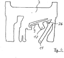
Fig. 6 wird die Kraft durch einen zwischen Rampe 9 und Federelement 11 angeordneten Steg 26 und einen Stützansatz 17 übertragen. Der Steg überträgt die Bewegung des Federelements 11 gemäß den wirkenden Hebelverhältnissen relativ zu einem fiktiven Drehpunkt. - Das Ausführungsbeispiel gemäß
Fig. 7 offenbart schließlich einen als flexiblen Steg ausgebildeten Stützansatz 17 zwischen Federelement 11 und Rampe 9, der einen Stützansatz überflüssig macht. Ein Ansatz 27 ist lediglich zur Verhinderung eines zu starken Einknickens und damit für den Schutz des Stegs vorgesehen.
Claims (12)
- Spender oder dgl. Ausgabebehälter insbesondere für Tabletten oder dergl. stückiges Gut (3) mit einem Gehäuse (1) und einem in dem Gehäuse (1) beweglich angeordneten Schieber (2), wobei eine Ausgabeöffnung (4) für vereinzeltes Gut (3) durch Betätigung des Schiebers (2) freigebbar ist, und wobei eine Rampe (9) zum Leiten des Guts (3) in Richtung der Ausgabeöffnung (4) an einem Teil (2) des Spenders festgelegt ist und gegenüber dem Teil des Spenders zur Positionsänderung des Gutes (3) beweglich ist, wobei die Rampe (9) als Teil des Schiebers (2) einstückig mit diesem ausgebildet ist und die Rampe nach oben bewegbar ist, um das Gut anzuheben, dadurch gekennzeichnet, dass die Rampe (9) in sich flexibel ausgebildet ist.
- Spender nach Anspruch 1, dadurch gekennzeichnet, dass die Rampe (9) in einem unteren Bereich des Spenders vor einer Vereinzelungskammer (6) angeordnet ist.
- Spender nach Anspruch 1 oder 2, gekennzeichnet durch einen ebenfalls beweglich angeordneten Mitnehmer (11) des Spenders, der zur Kraftübertragung auf die Rampe (9) ausgebildet ist.
- Spender nach Anspruch 3, dadurch gekennzeichnet, dass der Mitnehmer (11) des Spenders als Federelement ausgebildet ist.
- Spender nach Anspruch 3 oder 4, dadurch gekennzeichnet, dass der Mitnehmer (11) wenigstens eine auf die Bewegung der Rampe (9) wirkende Erhöhung (14) aufweist.
- Spender nach einem der Ansprüche 3 bis 5, dadurch gekennzeichnet, dass Mitnehmer (11) und Rampe (9) über einen festen flexiblen Steg (17) miteinander verbunden sind.
- Spender nach einem der vorherigen Ansprüche, dadurch gekennzeichnet, dass die Rampe mit einem Stützansatz (17) versehen ist, über den sich eine Bewegung des Schiebers (2) auf die Rampe (9) überträgt.
- Spender nach Anspruch 7, dadurch gekennzeichnet, dass der Stützansatz (17) flexibel ausgebildet ist.
- Spender nach Anspruch 7 oder 8, dadurch gekennzeichnet, dass der Stützansatz (17) eine Spitze (16) aufweist.
- Spender nach einem der vorherigen Ansprüche, dadurch gekennzeichnet, dass ein bei Betätigung des Schiebers (2) gegen eine Kante (22) des Gehäuses (1) anschlagender Fortsatz (21) über einen Sollbruchansatz mit dem Schieber (2) verbunden ist.
- Spender nach Anspruch 10, dadurch gekennzeichnet, dass der Fortsatz (21) einen eine geringfügige Bewegung des Schiebers (2) ohne Anschlagen an die Kante (22) ermöglichenden Abstand (B) zu dieser aufweist.
- Spender nach Anspruch 11, dadurch gekennzeichnet, dass der Abstand (B) zumindest 0,5 mm beträgt.
Applications Claiming Priority (2)
| Application Number | Priority Date | Filing Date | Title |
|---|---|---|---|
| DE202007013517U DE202007013517U1 (de) | 2007-09-27 | 2007-09-27 | Spender o.dgl. Ausgabebehälter |
| PCT/EP2008/007951 WO2009043493A1 (de) | 2007-09-27 | 2008-09-20 | Spender oder dergleichen ausgabebehälter |
Publications (3)
| Publication Number | Publication Date |
|---|---|
| EP2193088A1 EP2193088A1 (de) | 2010-06-09 |
| EP2193088B1 true EP2193088B1 (de) | 2018-05-16 |
| EP2193088B2 EP2193088B2 (de) | 2023-08-23 |
Family
ID=38831180
Family Applications (2)
| Application Number | Title | Priority Date | Filing Date |
|---|---|---|---|
| EP08802376.7A Not-in-force EP2193087B1 (de) | 2007-09-27 | 2008-09-19 | Spender oder dergleichen ausgabebehälter |
| EP08802453.4A Not-in-force EP2193088B2 (de) | 2007-09-27 | 2008-09-20 | Spender oder dergleichen ausgabebehälter |
Family Applications Before (1)
| Application Number | Title | Priority Date | Filing Date |
|---|---|---|---|
| EP08802376.7A Not-in-force EP2193087B1 (de) | 2007-09-27 | 2008-09-19 | Spender oder dergleichen ausgabebehälter |
Country Status (5)
| Country | Link |
|---|---|
| US (2) | US8439225B2 (de) |
| EP (2) | EP2193087B1 (de) |
| DE (2) | DE202007013517U1 (de) |
| RU (2) | RU2485037C2 (de) |
| WO (2) | WO2009043489A1 (de) |
Families Citing this family (9)
| Publication number | Priority date | Publication date | Assignee | Title |
|---|---|---|---|---|
| DE202007013517U1 (de) | 2007-09-27 | 2007-12-20 | Pöppelmann Holding GmbH & Co. KG | Spender o.dgl. Ausgabebehälter |
| DE202011100531U1 (de) | 2011-05-11 | 2012-08-14 | Pöppelmann Holding GmbH & Co. KG | Spender |
| DE202012003294U1 (de) | 2012-03-30 | 2013-07-01 | Pöppelmann Holding GmbH & Co. KG | Spender |
| CN104520208B (zh) * | 2012-05-22 | 2016-11-16 | 第一三共株式会社 | 药片取出管理容器 |
| DE202012005472U1 (de) | 2012-06-02 | 2013-09-11 | Pöppelmann Holding GmbH & Co. KG | Spender für Tabletten o.dgl. stückiges Gut |
| US10172765B2 (en) * | 2013-12-13 | 2019-01-08 | GlaxoSmithKline, LLC | Metered dose container |
| US10407235B2 (en) * | 2016-11-30 | 2019-09-10 | My Favorite Company, Inc. | Candy dispenser |
| CN106904376B (zh) * | 2017-04-21 | 2019-06-14 | 顺时实业(深圳)有限公司 | 一种方便取药的按压式药瓶 |
| ES2914403T3 (es) * | 2017-12-12 | 2022-06-10 | Gd Spa | Envase dispensador con abertura deslizante para artículos a granel |
Citations (12)
| Publication number | Priority date | Publication date | Assignee | Title |
|---|---|---|---|---|
| US3430810A (en) * | 1967-05-05 | 1969-03-04 | Albert H Baller | Dispenser with supply hold-back means |
| DE1536272A1 (de) | 1965-01-18 | 1969-11-27 | Safet Embamet Lethias | Ausgabeschachtel fuer Tabletten,Pastillen od.dgl. |
| DE3538923A1 (de) | 1985-11-02 | 1987-05-14 | Bramlage Gmbh | Spender fuer tabletten, kapseln oder dergleichen |
| US5139173A (en) | 1991-02-08 | 1992-08-18 | Evinger Donald J | Bulk product dispenser |
| GB2257421A (en) | 1991-07-02 | 1993-01-13 | Audus Noble Ltd | Tablet dispenser |
| EP0600123A1 (de) | 1992-12-03 | 1994-06-08 | Kerplas Neuenburg Gmbh Kunststoffverpackungen | Tablettenspender mit einer unteren Ausfallöffnung |
| WO1994014682A1 (de) | 1992-12-22 | 1994-07-07 | Jaco Dr. Jaeniche Gmbh & Co. Kg | Behältnis zur einzelportionierten ausgabe von tabletten oder dergleichen |
| EP0859725B1 (de) | 1995-06-08 | 2000-03-22 | Alain Ballester | Pastillen- und kapselspender |
| US20030234260A1 (en) | 2002-06-20 | 2003-12-25 | Giraud Jean Pierre | Dispenser for solid objects |
| DE202007013517U1 (de) | 2007-09-27 | 2007-12-20 | Pöppelmann Holding GmbH & Co. KG | Spender o.dgl. Ausgabebehälter |
| DE202007018407U1 (de) | 2007-03-16 | 2008-07-10 | Pöppelmann Holding GmbH & Co. KG | Spender |
| EP2873335A1 (de) | 2013-11-14 | 2015-05-20 | Thomas Lutz | Bekleidungsstück und Verfahren zur Herstellung desselben |
Family Cites Families (28)
| Publication number | Priority date | Publication date | Assignee | Title |
|---|---|---|---|---|
| US898914A (en) * | 1907-07-02 | 1908-09-15 | Edgar Byron Nichols | Match-box. |
| US2437498A (en) * | 1946-01-30 | 1948-03-09 | Bell Katherine Vena | Clothespin dispenser |
| DE3017376A1 (de) * | 1979-06-01 | 1981-11-12 | Bramlage Gmbh, 2842 Lohne | Behaeltnis zur einzel-portionierten ausgabe von tabletten |
| DE3018041A1 (de) * | 1979-06-23 | 1981-11-12 | Schuckmann, Alfred Von, 4178 Kevelaer | Behaeltnis zur einzel-portionierten ausgabe von tabletten |
| DE3101184A1 (de) † | 1981-01-16 | 1982-09-02 | Ferenc Ing.(grad.) 7805 Bötzingen Gallina | Einzeldosierer fuer tabletten |
| DE3266410D1 (en) * | 1981-10-24 | 1985-10-24 | Boots Co Plc | Tablet dispenser |
| DE3374550D1 (en) * | 1982-12-21 | 1987-12-23 | Johnsen Jorgensen Plastics Ltd | Dispensing container |
| DE3515302A1 (de) * | 1985-04-27 | 1986-10-30 | Bramlage Gmbh, 2842 Lohne | Spender zur ausgabe von tabletten |
| CH672772A5 (de) * | 1987-03-20 | 1989-12-29 | Alfatechnic Ag | |
| EP0287335A3 (de) * | 1987-04-14 | 1989-10-18 | BAXTER INTERNATIONAL INC. (a Delaware corporation) | Tablettenspender mit Zuführungshilfsmittel |
| DE8815878U1 (de) * | 1988-06-09 | 1989-10-12 | Bramlage Gmbh, 2842 Lohne | Spender zur einzel-portionierten Ausgabe von Tabletten |
| DE29514137U1 (de) * | 1995-09-02 | 1995-10-26 | Bramlage GmbH, 49393 Lohne | Tablettenspender |
| US5816441A (en) * | 1996-01-25 | 1998-10-06 | Kerr Group, Inc. | Tablet dispenser with child-resistant locking feature |
| DE29713884U1 (de) | 1997-08-05 | 1997-10-02 | RPC Bramlage GmbH, 49393 Lohne | Tablettenspender |
| FR2788040B1 (fr) * | 1998-12-31 | 2001-03-23 | Airsec Sa | Distributeur d'objets |
| FR2792621B1 (fr) * | 1999-04-23 | 2001-06-22 | Coradin | Dispositif de distribution de granules a rampe helicoidale |
| US6206235B1 (en) * | 1999-07-07 | 2001-03-27 | Daniel Green | Candy dispenser |
| US6494342B1 (en) * | 1999-10-27 | 2002-12-17 | Inland Finance Company | Dispensed product lift for vending machine |
| AT409366B (de) * | 2000-06-20 | 2002-07-25 | Haas Beteiligungsgesellschaft | Magazin zur aufnahme und vereinzelten abgabe von tabletten |
| AUPQ933700A0 (en) * | 2000-08-10 | 2000-08-31 | Western Research & Development Pty Ltd | Tamper proof product dispenser |
| US6948634B2 (en) * | 2001-05-25 | 2005-09-27 | Warner-Lambert Company Llc | Solid dosage form dispenser |
| US7243817B2 (en) * | 2002-10-10 | 2007-07-17 | Csp Technologies, Inc. | Solid objects dispensers |
| CA2543872A1 (en) * | 2003-10-27 | 2005-05-19 | Csp Technologies, Inc. | Solid objects dispensers having a dual lever mechanism |
| US7273156B2 (en) * | 2004-06-02 | 2007-09-25 | Kimberly-Clark Worldwide, Inc. | Adjustable sheet dispenser |
| JP2008539144A (ja) * | 2005-04-26 | 2008-11-13 | イー・アイ・デュポン・ドウ・ヌムール・アンド・カンパニー | 錠剤ディスペンサー |
| US7533785B2 (en) * | 2005-11-18 | 2009-05-19 | Seaquist Closures Foreign, Inc. | Tablet dispenser |
| NL2000463C2 (nl) * | 2007-02-01 | 2008-08-04 | Ind Ontwerpbureau Hsm B V | Inrichting voor het dispenseren van korrelvormige producten. |
| US7988016B2 (en) * | 2008-02-06 | 2011-08-02 | Klein Seth A | Medicine container with single pill dispenser |
-
2007
- 2007-09-27 DE DE202007013517U patent/DE202007013517U1/de not_active Expired - Lifetime
-
2008
- 2008-02-13 DE DE102008009021.2A patent/DE102008009021B4/de not_active Expired - Fee Related
- 2008-09-19 RU RU2010116341/12A patent/RU2485037C2/ru active
- 2008-09-19 US US12/678,910 patent/US8439225B2/en not_active Expired - Fee Related
- 2008-09-19 EP EP08802376.7A patent/EP2193087B1/de not_active Not-in-force
- 2008-09-19 WO PCT/EP2008/007861 patent/WO2009043489A1/de not_active Ceased
- 2008-09-20 RU RU2010116343/12A patent/RU2485038C2/ru active
- 2008-09-20 EP EP08802453.4A patent/EP2193088B2/de not_active Not-in-force
- 2008-09-20 WO PCT/EP2008/007951 patent/WO2009043493A1/de not_active Ceased
- 2008-09-20 US US12/678,931 patent/US20100258583A1/en not_active Abandoned
Patent Citations (12)
| Publication number | Priority date | Publication date | Assignee | Title |
|---|---|---|---|---|
| DE1536272A1 (de) | 1965-01-18 | 1969-11-27 | Safet Embamet Lethias | Ausgabeschachtel fuer Tabletten,Pastillen od.dgl. |
| US3430810A (en) * | 1967-05-05 | 1969-03-04 | Albert H Baller | Dispenser with supply hold-back means |
| DE3538923A1 (de) | 1985-11-02 | 1987-05-14 | Bramlage Gmbh | Spender fuer tabletten, kapseln oder dergleichen |
| US5139173A (en) | 1991-02-08 | 1992-08-18 | Evinger Donald J | Bulk product dispenser |
| GB2257421A (en) | 1991-07-02 | 1993-01-13 | Audus Noble Ltd | Tablet dispenser |
| EP0600123A1 (de) | 1992-12-03 | 1994-06-08 | Kerplas Neuenburg Gmbh Kunststoffverpackungen | Tablettenspender mit einer unteren Ausfallöffnung |
| WO1994014682A1 (de) | 1992-12-22 | 1994-07-07 | Jaco Dr. Jaeniche Gmbh & Co. Kg | Behältnis zur einzelportionierten ausgabe von tabletten oder dergleichen |
| EP0859725B1 (de) | 1995-06-08 | 2000-03-22 | Alain Ballester | Pastillen- und kapselspender |
| US20030234260A1 (en) | 2002-06-20 | 2003-12-25 | Giraud Jean Pierre | Dispenser for solid objects |
| DE202007018407U1 (de) | 2007-03-16 | 2008-07-10 | Pöppelmann Holding GmbH & Co. KG | Spender |
| DE202007013517U1 (de) | 2007-09-27 | 2007-12-20 | Pöppelmann Holding GmbH & Co. KG | Spender o.dgl. Ausgabebehälter |
| EP2873335A1 (de) | 2013-11-14 | 2015-05-20 | Thomas Lutz | Bekleidungsstück und Verfahren zur Herstellung desselben |
Also Published As
| Publication number | Publication date |
|---|---|
| US8439225B2 (en) | 2013-05-14 |
| DE102008009021B4 (de) | 2015-11-05 |
| EP2193088A1 (de) | 2010-06-09 |
| US20100258583A1 (en) | 2010-10-14 |
| RU2485038C2 (ru) | 2013-06-20 |
| EP2193087A1 (de) | 2010-06-09 |
| US20100258582A1 (en) | 2010-10-14 |
| RU2010116341A (ru) | 2011-11-10 |
| WO2009043493A1 (de) | 2009-04-09 |
| RU2485037C2 (ru) | 2013-06-20 |
| WO2009043489A1 (de) | 2009-04-09 |
| EP2193088B2 (de) | 2023-08-23 |
| EP2193087B1 (de) | 2016-06-22 |
| DE102008009021A1 (de) | 2009-04-02 |
| DE202007013517U1 (de) | 2007-12-20 |
| RU2010116343A (ru) | 2011-11-10 |
Similar Documents
| Publication | Publication Date | Title |
|---|---|---|
| EP2193088B1 (de) | Spender oder dergleichen ausgabebehälter | |
| DE69218789T2 (de) | Spender für pillen oder tabletten | |
| DE69806926T2 (de) | Vollständiges ausgabe-betätigungsmechanismus für aerosolspender | |
| EP1566606B1 (de) | Sicherung für eine Handfeuerwaffe | |
| AT502486B1 (de) | Anordnung mit einem scharnier, insbesondere möbelscharnier | |
| WO2013114348A1 (de) | Verfahren zur ausbildung eines tablettenspenders und tablettenspender | |
| DE102006037494A1 (de) | Türschließvorrichtung für ein elektrisches Haushaltsgerät, insbesondere eine Geschirrspülmschine | |
| EP2428271A2 (de) | Pipette für ein Pipettensystem mit Pipette und Spritze | |
| WO2010009910A2 (de) | Spendersystem | |
| EP1886939A2 (de) | Abgabekopf für einen Druckbehälter | |
| DE29713884U1 (de) | Tablettenspender | |
| EP2688677B1 (de) | Spender zur ausgabe flüssiger bis pastöser massen | |
| EP1586354B1 (de) | Langlauf- oder Telemarkbindung, sowie daran angepasste Schuhe | |
| DE2922269C2 (de) | Sohlenauflageplatte | |
| EP1606193B1 (de) | Tablettenspender | |
| EP0693439A1 (de) | Zerstäuberkappe für einen Behälter für ein unter Druck stehendes Fluid | |
| DE3417751A1 (de) | Behaeltnis zur einzel-portionierten ausgabe von tabletten | |
| EP1644267B1 (de) | Tablettenspender | |
| DE2512542C2 (de) | Behälter zur Aufnahme von Formkörpern, insbes. Tabletten | |
| DE4434933C2 (de) | Verschluß zur zentralen Ver- und Entriegelung von Schubladen | |
| EP2261140B1 (de) | Sprühkappe für einen mit einem Abgabeventil versehenen Druckbehälter | |
| DE3323898A1 (de) | Eiswuerfelspender | |
| DE202022002310U1 (de) | Spender für Einzelportionseinheiten | |
| DE3342884A1 (de) | Kindersichere schutzkappe fuer aerosolspruehdosen | |
| DE29800666U1 (de) | Tablettenspender |
Legal Events
| Date | Code | Title | Description |
|---|---|---|---|
| PUAI | Public reference made under article 153(3) epc to a published international application that has entered the european phase |
Free format text: ORIGINAL CODE: 0009012 |
|
| 17P | Request for examination filed |
Effective date: 20100324 |
|
| AK | Designated contracting states |
Kind code of ref document: A1 Designated state(s): AT BE BG CH CY CZ DE DK EE ES FI FR GB GR HR HU IE IS IT LI LT LU LV MC MT NL NO PL PT RO SE SI SK TR |
|
| AX | Request for extension of the european patent |
Extension state: AL BA MK RS |
|
| DAX | Request for extension of the european patent (deleted) | ||
| 17Q | First examination report despatched |
Effective date: 20121221 |
|
| STAA | Information on the status of an ep patent application or granted ep patent |
Free format text: STATUS: EXAMINATION IS IN PROGRESS |
|
| GRAP | Despatch of communication of intention to grant a patent |
Free format text: ORIGINAL CODE: EPIDOSNIGR1 |
|
| STAA | Information on the status of an ep patent application or granted ep patent |
Free format text: STATUS: GRANT OF PATENT IS INTENDED |
|
| GRAS | Grant fee paid |
Free format text: ORIGINAL CODE: EPIDOSNIGR3 |
|
| INTG | Intention to grant announced |
Effective date: 20180131 |
|
| GRAA | (expected) grant |
Free format text: ORIGINAL CODE: 0009210 |
|
| STAA | Information on the status of an ep patent application or granted ep patent |
Free format text: STATUS: THE PATENT HAS BEEN GRANTED |
|
| AK | Designated contracting states |
Kind code of ref document: B1 Designated state(s): AT BE BG CH CY CZ DE DK EE ES FI FR GB GR HR HU IE IS IT LI LT LU LV MC MT NL NO PL PT RO SE SI SK TR |
|
| REG | Reference to a national code |
Ref country code: GB Ref legal event code: FG4D Free format text: NOT ENGLISH |
|
| REG | Reference to a national code |
Ref country code: CH Ref legal event code: EP |
|
| REG | Reference to a national code |
Ref country code: IE Ref legal event code: FG4D Free format text: LANGUAGE OF EP DOCUMENT: GERMAN |
|
| REG | Reference to a national code |
Ref country code: DE Ref legal event code: R096 Ref document number: 502008016083 Country of ref document: DE |
|
| REG | Reference to a national code |
Ref country code: AT Ref legal event code: REF Ref document number: 999334 Country of ref document: AT Kind code of ref document: T Effective date: 20180615 |
|
| REG | Reference to a national code |
Ref country code: NL Ref legal event code: MP Effective date: 20180516 |
|
| REG | Reference to a national code |
Ref country code: LT Ref legal event code: MG4D |
|
| PG25 | Lapsed in a contracting state [announced via postgrant information from national office to epo] |
Ref country code: ES Free format text: LAPSE BECAUSE OF FAILURE TO SUBMIT A TRANSLATION OF THE DESCRIPTION OR TO PAY THE FEE WITHIN THE PRESCRIBED TIME-LIMIT Effective date: 20180516 Ref country code: LT Free format text: LAPSE BECAUSE OF FAILURE TO SUBMIT A TRANSLATION OF THE DESCRIPTION OR TO PAY THE FEE WITHIN THE PRESCRIBED TIME-LIMIT Effective date: 20180516 Ref country code: NO Free format text: LAPSE BECAUSE OF FAILURE TO SUBMIT A TRANSLATION OF THE DESCRIPTION OR TO PAY THE FEE WITHIN THE PRESCRIBED TIME-LIMIT Effective date: 20180816 Ref country code: FI Free format text: LAPSE BECAUSE OF FAILURE TO SUBMIT A TRANSLATION OF THE DESCRIPTION OR TO PAY THE FEE WITHIN THE PRESCRIBED TIME-LIMIT Effective date: 20180516 Ref country code: BG Free format text: LAPSE BECAUSE OF FAILURE TO SUBMIT A TRANSLATION OF THE DESCRIPTION OR TO PAY THE FEE WITHIN THE PRESCRIBED TIME-LIMIT Effective date: 20180816 Ref country code: SE Free format text: LAPSE BECAUSE OF FAILURE TO SUBMIT A TRANSLATION OF THE DESCRIPTION OR TO PAY THE FEE WITHIN THE PRESCRIBED TIME-LIMIT Effective date: 20180516 |
|
| PG25 | Lapsed in a contracting state [announced via postgrant information from national office to epo] |
Ref country code: GR Free format text: LAPSE BECAUSE OF FAILURE TO SUBMIT A TRANSLATION OF THE DESCRIPTION OR TO PAY THE FEE WITHIN THE PRESCRIBED TIME-LIMIT Effective date: 20180817 Ref country code: HR Free format text: LAPSE BECAUSE OF FAILURE TO SUBMIT A TRANSLATION OF THE DESCRIPTION OR TO PAY THE FEE WITHIN THE PRESCRIBED TIME-LIMIT Effective date: 20180516 Ref country code: LV Free format text: LAPSE BECAUSE OF FAILURE TO SUBMIT A TRANSLATION OF THE DESCRIPTION OR TO PAY THE FEE WITHIN THE PRESCRIBED TIME-LIMIT Effective date: 20180516 Ref country code: NL Free format text: LAPSE BECAUSE OF FAILURE TO SUBMIT A TRANSLATION OF THE DESCRIPTION OR TO PAY THE FEE WITHIN THE PRESCRIBED TIME-LIMIT Effective date: 20180516 |
|
| PG25 | Lapsed in a contracting state [announced via postgrant information from national office to epo] |
Ref country code: RO Free format text: LAPSE BECAUSE OF FAILURE TO SUBMIT A TRANSLATION OF THE DESCRIPTION OR TO PAY THE FEE WITHIN THE PRESCRIBED TIME-LIMIT Effective date: 20180516 Ref country code: CZ Free format text: LAPSE BECAUSE OF FAILURE TO SUBMIT A TRANSLATION OF THE DESCRIPTION OR TO PAY THE FEE WITHIN THE PRESCRIBED TIME-LIMIT Effective date: 20180516 Ref country code: SK Free format text: LAPSE BECAUSE OF FAILURE TO SUBMIT A TRANSLATION OF THE DESCRIPTION OR TO PAY THE FEE WITHIN THE PRESCRIBED TIME-LIMIT Effective date: 20180516 Ref country code: PL Free format text: LAPSE BECAUSE OF FAILURE TO SUBMIT A TRANSLATION OF THE DESCRIPTION OR TO PAY THE FEE WITHIN THE PRESCRIBED TIME-LIMIT Effective date: 20180516 Ref country code: DK Free format text: LAPSE BECAUSE OF FAILURE TO SUBMIT A TRANSLATION OF THE DESCRIPTION OR TO PAY THE FEE WITHIN THE PRESCRIBED TIME-LIMIT Effective date: 20180516 Ref country code: EE Free format text: LAPSE BECAUSE OF FAILURE TO SUBMIT A TRANSLATION OF THE DESCRIPTION OR TO PAY THE FEE WITHIN THE PRESCRIBED TIME-LIMIT Effective date: 20180516 |
|
| REG | Reference to a national code |
Ref country code: DE Ref legal event code: R026 Ref document number: 502008016083 Country of ref document: DE |
|
| PLBI | Opposition filed |
Free format text: ORIGINAL CODE: 0009260 |
|
| PG25 | Lapsed in a contracting state [announced via postgrant information from national office to epo] |
Ref country code: IT Free format text: LAPSE BECAUSE OF FAILURE TO SUBMIT A TRANSLATION OF THE DESCRIPTION OR TO PAY THE FEE WITHIN THE PRESCRIBED TIME-LIMIT Effective date: 20180516 |
|
| PLAX | Notice of opposition and request to file observation + time limit sent |
Free format text: ORIGINAL CODE: EPIDOSNOBS2 |
|
| 26 | Opposition filed |
Opponent name: RPC BRAMLAGE GMBH Effective date: 20190214 |
|
| PG25 | Lapsed in a contracting state [announced via postgrant information from national office to epo] |
Ref country code: MC Free format text: LAPSE BECAUSE OF FAILURE TO SUBMIT A TRANSLATION OF THE DESCRIPTION OR TO PAY THE FEE WITHIN THE PRESCRIBED TIME-LIMIT Effective date: 20180516 |
|
| REG | Reference to a national code |
Ref country code: CH Ref legal event code: PL |
|
| GBPC | Gb: european patent ceased through non-payment of renewal fee |
Effective date: 20180920 |
|
| PG25 | Lapsed in a contracting state [announced via postgrant information from national office to epo] |
Ref country code: SI Free format text: LAPSE BECAUSE OF FAILURE TO SUBMIT A TRANSLATION OF THE DESCRIPTION OR TO PAY THE FEE WITHIN THE PRESCRIBED TIME-LIMIT Effective date: 20180516 |
|
| REG | Reference to a national code |
Ref country code: BE Ref legal event code: MM Effective date: 20180930 |
|
| REG | Reference to a national code |
Ref country code: IE Ref legal event code: MM4A |
|
| PG25 | Lapsed in a contracting state [announced via postgrant information from national office to epo] |
Ref country code: LU Free format text: LAPSE BECAUSE OF NON-PAYMENT OF DUE FEES Effective date: 20180920 |
|
| PLBB | Reply of patent proprietor to notice(s) of opposition received |
Free format text: ORIGINAL CODE: EPIDOSNOBS3 |
|
| PG25 | Lapsed in a contracting state [announced via postgrant information from national office to epo] |
Ref country code: IE Free format text: LAPSE BECAUSE OF NON-PAYMENT OF DUE FEES Effective date: 20180920 |
|
| PG25 | Lapsed in a contracting state [announced via postgrant information from national office to epo] |
Ref country code: LI Free format text: LAPSE BECAUSE OF NON-PAYMENT OF DUE FEES Effective date: 20180930 Ref country code: CH Free format text: LAPSE BECAUSE OF NON-PAYMENT OF DUE FEES Effective date: 20180930 Ref country code: FR Free format text: LAPSE BECAUSE OF NON-PAYMENT OF DUE FEES Effective date: 20180930 Ref country code: BE Free format text: LAPSE BECAUSE OF NON-PAYMENT OF DUE FEES Effective date: 20180930 |
|
| PG25 | Lapsed in a contracting state [announced via postgrant information from national office to epo] |
Ref country code: GB Free format text: LAPSE BECAUSE OF NON-PAYMENT OF DUE FEES Effective date: 20180920 |
|
| REG | Reference to a national code |
Ref country code: AT Ref legal event code: MM01 Ref document number: 999334 Country of ref document: AT Kind code of ref document: T Effective date: 20180920 |
|
| PG25 | Lapsed in a contracting state [announced via postgrant information from national office to epo] |
Ref country code: MT Free format text: LAPSE BECAUSE OF FAILURE TO SUBMIT A TRANSLATION OF THE DESCRIPTION OR TO PAY THE FEE WITHIN THE PRESCRIBED TIME-LIMIT Effective date: 20180516 Ref country code: AT Free format text: LAPSE BECAUSE OF NON-PAYMENT OF DUE FEES Effective date: 20180920 |
|
| PG25 | Lapsed in a contracting state [announced via postgrant information from national office to epo] |
Ref country code: TR Free format text: LAPSE BECAUSE OF FAILURE TO SUBMIT A TRANSLATION OF THE DESCRIPTION OR TO PAY THE FEE WITHIN THE PRESCRIBED TIME-LIMIT Effective date: 20180516 |
|
| PG25 | Lapsed in a contracting state [announced via postgrant information from national office to epo] |
Ref country code: HU Free format text: LAPSE BECAUSE OF FAILURE TO SUBMIT A TRANSLATION OF THE DESCRIPTION OR TO PAY THE FEE WITHIN THE PRESCRIBED TIME-LIMIT; INVALID AB INITIO Effective date: 20080920 Ref country code: PT Free format text: LAPSE BECAUSE OF FAILURE TO SUBMIT A TRANSLATION OF THE DESCRIPTION OR TO PAY THE FEE WITHIN THE PRESCRIBED TIME-LIMIT Effective date: 20180516 |
|
| PG25 | Lapsed in a contracting state [announced via postgrant information from national office to epo] |
Ref country code: CY Free format text: LAPSE BECAUSE OF FAILURE TO SUBMIT A TRANSLATION OF THE DESCRIPTION OR TO PAY THE FEE WITHIN THE PRESCRIBED TIME-LIMIT Effective date: 20180516 |
|
| PG25 | Lapsed in a contracting state [announced via postgrant information from national office to epo] |
Ref country code: IS Free format text: LAPSE BECAUSE OF FAILURE TO SUBMIT A TRANSLATION OF THE DESCRIPTION OR TO PAY THE FEE WITHIN THE PRESCRIBED TIME-LIMIT Effective date: 20180916 |
|
| APAH | Appeal reference modified |
Free format text: ORIGINAL CODE: EPIDOSCREFNO |
|
| APBM | Appeal reference recorded |
Free format text: ORIGINAL CODE: EPIDOSNREFNO |
|
| APBP | Date of receipt of notice of appeal recorded |
Free format text: ORIGINAL CODE: EPIDOSNNOA2O |
|
| APBQ | Date of receipt of statement of grounds of appeal recorded |
Free format text: ORIGINAL CODE: EPIDOSNNOA3O |
|
| APBU | Appeal procedure closed |
Free format text: ORIGINAL CODE: EPIDOSNNOA9O |
|
| PUAH | Patent maintained in amended form |
Free format text: ORIGINAL CODE: 0009272 |
|
| STAA | Information on the status of an ep patent application or granted ep patent |
Free format text: STATUS: PATENT MAINTAINED AS AMENDED |
|
| 27A | Patent maintained in amended form |
Effective date: 20230823 |
|
| AK | Designated contracting states |
Kind code of ref document: B2 Designated state(s): AT BE BG CH CY CZ DE DK EE ES FI FR GB GR HR HU IE IS IT LI LT LU LV MC MT NL NO PL PT RO SE SI SK TR |
|
| REG | Reference to a national code |
Ref country code: DE Ref legal event code: R102 Ref document number: 502008016083 Country of ref document: DE |
|
| PGFP | Annual fee paid to national office [announced via postgrant information from national office to epo] |
Ref country code: DE Payment date: 20230919 Year of fee payment: 16 |
|
| REG | Reference to a national code |
Ref country code: DE Ref legal event code: R119 Ref document number: 502008016083 Country of ref document: DE |
|
| PG25 | Lapsed in a contracting state [announced via postgrant information from national office to epo] |
Ref country code: DE Free format text: LAPSE BECAUSE OF NON-PAYMENT OF DUE FEES Effective date: 20250401 |