EP2193248B1 - Panneau d'obturation de baie de serveur et système associé - Google Patents
Panneau d'obturation de baie de serveur et système associé Download PDFInfo
- Publication number
- EP2193248B1 EP2193248B1 EP08795494.7A EP08795494A EP2193248B1 EP 2193248 B1 EP2193248 B1 EP 2193248B1 EP 08795494 A EP08795494 A EP 08795494A EP 2193248 B1 EP2193248 B1 EP 2193248B1
- Authority
- EP
- European Patent Office
- Prior art keywords
- panel
- aperture
- server rack
- pieces
- scoring
- Prior art date
- Legal status (The legal status is an assumption and is not a legal conclusion. Google has not performed a legal analysis and makes no representation as to the accuracy of the status listed.)
- Active
Links
Images


Classifications
-
- H—ELECTRICITY
- H05—ELECTRIC TECHNIQUES NOT OTHERWISE PROVIDED FOR
- H05K—PRINTED CIRCUITS; CASINGS OR CONSTRUCTIONAL DETAILS OF ELECTRIC APPARATUS; MANUFACTURE OF ASSEMBLAGES OF ELECTRICAL COMPONENTS
- H05K7/00—Constructional details common to different types of electric apparatus
- H05K7/14—Mounting supporting structure in casing or on frame or rack
- H05K7/1485—Servers; Data center rooms, e.g. 19-inch computer racks
- H05K7/1488—Cabinets therefor, e.g. chassis or racks or mechanical interfaces between blades and support structures
Definitions
- This invention relates generally to a panel and system that restricts airflow relative to computer server racks. More specifically, it relates to an assembly of at least one panel on at least one computer server rack, where the panel is scalable, meaning that it may be adjusted to conform to the open and unoccupied facial space on the server rack, so as to aid in preventing the circular flow and re-entry of high temperature air into the air intake of a server, thereby aiding in preventing the overheating of the server.
- Computer equipment and data centers have thermal cooling requirements in order to function properly.
- a high amount of electricity is required for one server to operate, which generates a great deal of heat within the casing of the server. This heat can cause numerous problems for the equipment, including operational failures and physical damage.
- internal fans are typically integrated into the server to provide both an intake of cooler air, which may be ambient or conditioned, and an output of hot air. Most commonly, the intake of cooler air occurs at the front of the server, and the output of hot air occurs at the rear of the server. Servers are housed in server racks.
- the servers When stored in server racks, the servers are all typically aligned such that the cooler air intake for all of the servers is on one side of the server rack, preferably the front of the rack, and the hot air output for all of the servers is on the other side of the server rack, preferably the rear of the rack.
- This arrangement of one or more servers creates an air flow from the front of the server rack to the rear of the server rack, where the flow can intensify with an increase in the number of servers, due to the BTU output or certain types of high amperage Blade servers producing high amounts of heat.
- a problem may arise, however, when a server rack is not completely filled with servers.
- This empty space may permit the air intake of a server to draw the air output from the rear of the server, creating a cycle of air around and to the front of the server.
- Such a cycling of air does not permit cooler air to be drawn in, but instead draws in warm air that does not aid in the cooling of the server equipment, and instead can cause the server to overheat.
- some data centers have installed panels to cover the space that would normally be covered by a face of a server. This covering blocks the circulation of warm air output into the air intake and allows whatever systems are in place within the data center to provide cooler air, such as a Computer Room Air Conditioner (CRAC), to effectively cool the servers.
- CRAC Computer Room Air Conditioner
- Server rack-mounted equipment are typically measured against an international standard known as the Electronic Industries Alliance (EIA) standard unit, also known as a Rack Unit, or a Rack U (U).
- EIA Electronic Industries Alliance
- Each U is equal to 4.4 centimeters (1.75 inches) in height, and the height of server racks is commonly described in the art as being a certain number of U's high.
- Server racks may be of any height, however they are typically of a height of between 42 U to 46 U, or greater.
- Existing means for covering server racks spaces may include the use of tools, such as drills, that can damage the material to cover the spaces, as well as be inaccurate and create additional waste or messes.
- Existing means for affixing the material to the server racks 'to cover the spaces may include tape, Velcro, magnets and other inefficient means.
- the face plate has a height corresponding to multiples of 4.45 centimetres (1.75 inches).
- the face plate incorporates a means for slidably receiving fasteners.
- the blank panel further comprises fasteners with mating portions for being slidably engaged with the face plate, and fastening portions for being further attachable to a rack unit.
- the fasteners have varied geometry to accommodate rack units with alternate configurations.
- the blank panel further comprises a plurality of face plates attached along the top and bottom plate surfaces. Each of the face plates is capable of individually receiving fasteners.
- the individual face plates of the blank panel are also modular and can be separated to configure the blank panel to varied height requirements.
- the present invention meets the need in the art by providing a scalable system that allows for a single panel of the invention to be easily modified, preferably without the use of tools, to fit on a server rack, preferably a server rack that meets EIA Mounting Rail Specification EIA 310, where the single panel is so modified as to cover the desired amount of open space on a server rack, where the panel is fire-rated, and where the modified panel may be easily installed onto the server rack to as to cover the open space thereon, and prevents the circular flow of warm air output from entering the cooler air input of the servers housed on the server rack. It is within the spirit and scope of this invention for multiple panels of the invention to be used on a single server rack, which will depend on the configuration, and hence the open space of a server rack. It is an object of the present invention to provide a system that conforms to and is compatible with EIA standards.
- FIG. 6 is a close up view of a portion of a server rack, showing EIA 310 standard spacing between the holes in the rack, as well as the relative location of the rack unit to the holes on a server rack. Additionally, EIA 310 standards dictate that the height of a single Rack Unit (U or RU) is 4.4 centimetres (1.75 inches).
- EIA standards further dictate that the horizontal spacing between the two rails in a server rack are 45.1 centimetres (17.75 inches), and that the horizontal spacing between two holes on opposing rails in a rack are 46.514 centimetres (18.3125 inches) from the center of one hole to the center of the other hole.
- the system is adjustable in height, which is achieved by the separation of panel pieces along scored perforations between the pieces.
- the system can be easily reconfigured as spatial needs change.
- the system When installed, the system restricts airflow around servers within the racks. By restricting airflow, the system allows data centers to save electricity and costs associated with electricity usage, as well as additional costs associated with maintaining and replacing servers or server equipment due to overheating, elongating the equipment life. In many circumstances, installation of the system may lower costs associated with the purchase of one or more computer room air conditioning units. By increasing efficiency of such an air conditioning unit, the invention may lower electricity costs.
- the system may reduce the number of such air conditioning units required to cool a data center, when used in concert with additional air restriction or control means, such as sub-plenum or baffling.
- the system is removable and repositionable thereby allowing data center managers increased flexibility in arranging equipment within a data center.
- the system according to the present invention is constructed of material that is more flexible and easier to work with than sheet metal, fiberglass, or other materials currently known in the art.
- the cost of labor for installation of the system may also be less expensive than the professional installation of substitute materials, due to the ease of installation.
- the invention is an EIA rack enclosure blanking panel system comprised of lightweight and flexible material that may be easily modified and easily installed upon computer server racks without destructive attachment to the racks, or any additional equipment. After installation, blanking panel pieces of the system may be easily removed from the server rack. Upon removal from the server rack, the pieces may be further separated from each other and re-installed upon the server racks.
- the blanking panel pieces are scored to allow for break-apart sizing and shaping. Due to their break-apart or tear-away construct the desired configuration of blanking panel pieces may be achieved with or without tools.
- the panel is between about 47.6 centimetres to about 49.5 centimetres (18.75 inches to about 19.50 inches) wide. In a preferred embodiment, the panel is between about 48.3 centimetres to about 48.9 centimetres (19.00 inches to about 19.25 inches) wide. In a particularly preferred embodiment, the panel is about 48.3 centimetres (19.00 inches) wide, more preferably exactly 48.3 centimetres (19.00 inches) wide. In another particularly preferred embodiment, the panel is about 48.8 centimetres (19.25 inches) wide, more preferably exactly 48.8 centimetres (19.25 inches) wide.
- the panel is several U's in height, more preferably 27 U's in height or greater.
- the panel is scored horizontally such that the panel is divided into equal, substantially identical separable pieces, each piece being about one U in height.
- each piece is exactly one U in height.
- each piece on a panel is exactly two U in height.
- each piece on a panel is uniform in height throughout the panel, and the height of each piece is n U in height, where n is an integer.
- n is an integer.
- in a 27 U panel there may be nine pieces, each piece being 3 U high.
- in a 27 U panel there may be 27 pieces, each being 1 U high.
- the pieces on a single panel are not uniform in height throughout the panel, but rather are of a of variety heights, where the height of any individual piece may be represented as y U high, where y is an integer.
- y U high where y is an integer.
- the panel comprises a single piece that is z U high, where z is an integer.
- z is an integer.
- in a 27 U panel there is one piece that is 27 U high.
- the panel is further scored, in addition to the scoring between the pieces, such that, on both of the opposite horizontal ends of each piece of the panel, an aperture scoring is present.
- the panel is further scored, in addition to the scoring between the pieces, such that, on the opposite horizontal ends of each piece of the panel, three aperture scorings are present.
- the aperture scorings are present such that the panel of the present invention substantially corresponds with at least some of the rail holes of a server rack that substantially complies with EIA mounting hole locations.
- the panel is further scored, in addition to the scoring between the pieces, such that, on the opposite horizontal ends of each piece of the panel, at least one aperture scoring, in the shape of a circle, is present.
- the panel is further scored, in addition to the scoring between the pieces, such that, on the opposite horizontal ends of each piece of the panel, at least one aperture scoring, in the shape of an ellipse, is present.
- the panel is further scored, in addition to the scoring between the pieces, such that, on the opposite horizontal ends of each piece of the panel, at least one aperture scoring, in the shape of a rectangle, is present.
- the panel is further scored, in addition to the scoring between the pieces, such that, on the opposite horizontal ends of each piece of the panel, at least one aperture scoring, in the shape of a 'T' shape, is present, where a 'T shape' refers to a shape that comprises two substantially perpendicular line segments of some width greater than zero, where one line segment terminates at the midpoint of the other line segment.
- the panel is further scored, in addition to the scoring between the pieces, such that, on the opposite horizontal ends of each piece of the panel, at least one aperture scoring, in the shape of a half-racetrack, or a 'U' shape, is present.
- the panel is further scored, in addition to the scoring between the pieces, such that, on the opposite horizontal ends of each piece of the panel, at least one aperture scoring, in a rounded 'T' shape, is present.
- the panel is further scored, in addition to the scoring between the pieces, such that, on the opposite horizontal ends of each piece of the panel, at least one aperture scoring, in a rounded rectangle shape, is present.
- the aperture scoring is uniform throughout the panel, and occurs halfway up each piece vertically.
- n U high that piece has 2 n aperture scorings, where n is an integer, and the piece has an even amount of aperture scorings on each opposite end of the piece, and the aperture scorings are evenly spaced through the opposite horizontal ends of the piece.
- a piece is n U high
- that piece has four aperture scorings, located substantially near the four corners of the piece.
- Scored or “scoring” as used in this patent application are defined to include marks or lines created upon a surface by way of scoring, press-cutting, perforating, etching, laser cutting, knife cutting, or any other technique that results in the incomplete cutting or removal of material.
- the aperture scoring areas of the panel pieces constitute "pop-out sections.” These pop-out sections may be removed by hand from the panel pieces by application of pressure applied upon the area of the panel pieces within the aperture scoring outline. In the preferred embodiment, the pressure necessary to remove the pop-out section is finger pressure. Alternatively, the pop-out section can be pressed out with a tool or can be cut out by drawing a knife-edge or sharp tool along the scored outline. Once the pop-out section is removed, a fastener-accepting aperture results in the location of the former pop-out section.
- the panel should be of a relatively thin material. In a preferred embodiment, the panel should be of a relatively thin, fire-retardant material. In a preferred embodiment, the panel should be thin enough that it may be readily attached to a server panel through the use of mounting equipment known by those of ordinary skill in the art, such as brackets, screws, pins, pegs, bolts, hooks and other similar equipment.
- the panel may be substantially comprised of thermoplastic material, such as Acrylonitrile butadiene styrene (ABS). In another preferred embodiment, the panel may be substantially comprised of Chlorinated Polyvinyl Chloride or Chlorinated Polyvinylidine Chloride.
- the panel may be substantially comprised of Polyphenylene oxide-styrene (POS). In another preferred embodiment, the panel may be substantially comprised of plexiglass. In another preferred embodiment, the panel may be substantially comprised of high-density polyethylene (HDPE). In another preferred embodiment, the panel may be substantially comprised of any polypropylene compound.
- POS Polyphenylene oxide-styrene
- HDPE high-density polyethylene
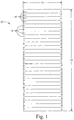
- FIG. 1 there is shown generally an embodiment of a full panel 10 of the present invention, this particular panel being about 27 U in height 14.
- Each piece 16 is uniform in height and width 12, and each piece has two half-racetrack shaped scoring apertures 18 on the opposite ends of the piece 16.
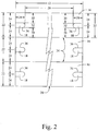
- FIG. 2 there is shown a close up view of an embodiment of three joined panel pieces 16, where a pair of jagged lines 20 represents a continuation of the pieces, which has been done to fit the figure onto one page for close inspection.
- Each piece is uniform in height 22 and width 12, and each piece 16 has two half-racetrack shaped scoring apertures 18 on the opposite ends of the piece 16.
- Each aperture 18 is located within the center of the edge of the piece on which the aperture resides, such that the measurements 30 from the each of the edges of the apertures 18 to the scored edges of the piece on which it resides are equidistant.
- the center of the aperture 18 is aligned such that it is halfway down the edge of the piece 24.
- Each aperture is of a uniform length 28 and height 32, and in a uniform location throughout all of the pieces 16 of the panel.
- the apertures 18 on each piece 16 are equidistant 26 from each other throughout the panel.
- Each piece 16 has been scored 34 so as to permit ready separation from adjacent pieces 16.
- Each aperture 18 has been scored 36 so as to permit ready separation from the piece 16 on which it resides.
- FIG. 3 there is shown generally another embodiment of a full panel 10 of the present invention, this particular panel being about 27 U in height 14.
- Each piece 16 is uniform in height and width 12, and each piece has two rounded T shaped scoring apertures 38 on the opposite ends of the piece 16.
- FIG. 4 there is shown a close up view of an embodiment of three joined panel pieces 16, where a pair of jagged lines 20 represents a continuation of the pieces, which has been done to fit the figure onto one page for close inspection.
- Each piece is uniform in height 22 and width 12, and each piece 16 has two rounded T shaped scoring apertures 38 on the opposite ends of the piece 16.
- Each aperture 38 is located within the center of the edge of the piece on which the aperture resides, such that the measurements 30 from the each of the edges of the apertures 38 to the scored edges of the piece on which it resides are equidistant.
- the center of the aperture 38 is aligned such that it is halfway down the edge of the piece 24.
- Each aperture is of a uniform length 28.
- Each aperture is of a uniform height, both in the narrowest height 40 and in the widest height 42. Each aperture is in a uniform location throughout all of the pieces 16 of the panel. Each aperture is of a uniform depth 44 from the edge of the piece to the widest region of the aperture. Each aperture is of a uniform depth 46 throughout the widest region of the aperture.
- the apertures 38 on each piece 16 are equidistant 26 from each other throughout the panel. Each piece 16 has been scored 34 so as to permit ready separation from adjacent pieces 16. Each aperture 38 has been scored 36 so as to permit ready separation from the piece 16 on which it resides. In this particular embodiment, the scoring 34 between the pieces results in nicks 48 that serve to hold the pieces 16 together until perforation. The spacing 50 between the nicks 48 is uniform in length throughout the perforations between the pieces.
- FIG. 5 there is shown a close up view of yet another embodiment of three joined panel pieces 16, where a pair of jagged lines 20 represents a continuation of the pieces, which has been done to fit the figure onto one page for close inspection.
- Each piece is uniform in height 22 and width 12, and each piece 16 has two rounded rectangle shaped scoring apertures 52 on the opposite ends of the piece 16.
- Each aperture 52 is located within the center of the edge of the piece on which the aperture resides, such that the measurements 30 from the each of the edges of the apertures 52 to the scored edges of the piece on which it resides are equidistant.
- the center of the aperture 52 is aligned such that it is halfway down the edge of the piece 24.
- Each aperture is in a uniform location throughout all of the pieces 16 of the panel.
- Each aperture is located at a uniform depth 54 from the edge of the piece to the outermost edge of the aperture. Each aperture is located at a uniform depth 62 from the edge of the piece to the innermost edge of the aperture. Each aperture is of a uniform height 56. Each aperture is of a uniform width 58.
- the apertures 52 on each piece 16 are equidistant 26 from each other throughout the panel. The centers of the apertures 52 on each piece 16 are equidistant 60 from each other throughout the panel.
- Each piece 16 has been scored 34 so as to permit ready separation from adjacent pieces 16.
- Each aperture 52 has been scored 36 so as to permit ready separation from the piece 16 on which it resides. In this particular embodiment, the scoring 34 between the pieces results in nicks 48 that serve to hold the pieces 16 together until perforation.
- the spacing 50 between the nicks 48 is uniform in length throughout the perforations between the pieces.
- scoring apertures regardless of the width of the panel piece, the scoring apertures will substantially align with at least two opposing rack holes of an EIA compliant frame.
- each panel piece has been scored on the ends of the panel piece, such that a half-racetrack shaped scoring aperture is present on each end, each aperture located substantially in the center of the respective vertical edges of the piece, each aperture being between about 0.64 to about 0.95 centimetres (about 0.250 to about 0.375 inches) high, and being located between about 1.59 to about 2.22 centimetres (about 0.625 to about 0.875 inches) from the vertical edge of the piece on both sides of the aperture, each aperture being about 1.746 centimetres (0.6875 inches) deep, measured horizontally from the edge of the piece to the furthest inside edge of the aperture.
- each panel piece has been scored on the ends of the panel piece, such that a rounded T shaped scoring aperture is present on each end, each aperture located substantially in the center of the respective vertical edges of the piece, each aperture being between about 0.51 to about 0.95 centimetres (about 0.200 to about 0.375 inches) high at the narrowest region and being between about 0.76 to about 1.27 centimetres (about 0.300 to about 0.500 inches) high at the highest region.
- the apertures are located between about 0.76 to about 1.02 centimetres (about 0.300 to about 0.400 inches) from the edge of the end of the piece to the innermost scoring of the aperture.
- each panel piece has been scored on the ends of the panel piece, such that a rounded rectangle shaped scoring aperture is present on each end, each aperture located substantially in the center of the respective vertical edges of the piece, each aperture being between about 0.89 to about 1.27 centimetres (about 0.350 to about 0.500 inches) high and being between about 0.51 to about 0.95 centimetres (about 0.200 to about 0.375 inches) wide.
- the apertures are located between about 1.84 to about 1.97 centimetres (about 0.725 to about 0.775 inches) from the vertical edge of the piece on both sides of the aperture.
- each aperture is about 1.746 centimetres (0.6875 inches) deep, measured horizontally from the edge of the piece to the furthest inside edge of the aperture.
- the panel pieces have been scored such that between the scored pieces results are nicks that serve to hold the pieces together until perforation.
- the spacing between the nicks is uniform in length throughout the perforations between the pieces, and is preferably between about 0.51 to about 2.54 centimetres (about 0.200 to about 1.000 inches), more preferably between about 0.63 to about 1.27 centimetres (about 0.250 to about 0.500 inches).
- the nicks are of a uniform length throughout the perforations between the pieces, and are preferably between about 0.3969 to about 0.63 centimetres (about 0.15625 to about 0.250 inches) in length, and are preferably about 0.0794 centimetres (0.03125 inches) in length.
- each panel piece has been scored three times on each of the ends of the panel piece, such that a series of three scoring apertures are present on each end, each aperture located equidistant from the two most adjacent scorings, whether those scorings are for an adjacent aperture or a scoring between two panel pieces, or the edge of the panel.
- each panel piece has been scored three times on each of the ends of the panel piece, such that a series of three half-racetrack shaped scoring apertures are present on each end, each aperture located equidistant from the two most adjacent scorings, whether those scorings are for an adjacent aperture or a scoring between two panel pieces, or the edge of the panel.
- each aperture is between about 0.63 to about 0.95 centimetres (about 0.250 to about 0.375 inches) high, and is about 1.746 centimetres (0.6875 inches) deep, measured horizontally from the edge of the piece to the furthest inside edge of the aperture.
- the system comprises a 27 U panel, where the panel is about 48.9 centimetres (19.25 inches) wide, and is about 120.0 centimetres (47.25 inches) high.
- the panel has been scored such that each piece of the panel may be readily separated from the pieces directly adjacent to each piece, and has been scored so as to substantially prevent air flow through the scoring.
- each panel piece has been additionally scored on the ends of the panel piece, such that a half-racetrack shaped scoring aperture is present on each end, each aperture located substantially in the center of the respective vertical edges of the piece, each aperture being about 0.63 centimetres (0.250 inches) high, and being located about 2.22 centimetres (0.875 inches) from the vertical edge of the piece on both sides of the aperture, each aperture being about 1.746 centimetres (0.6875 inches) deep, measured horizontally from the edge of the piece to the furthest inside edge of the aperture.
- the panel has been scored such that each half-racetrack shaped scoring aperture may be readily separated from the pieces on which it resides, and has been scored so as to substantially prevent air flow through the scoring.
- rounded rectangle refers to a shape that is substantially rectangular, which includes a shape that is square, where the four corners have been rounded into equal arcical segments of ninety degrees.
- rounded T refers to a shape that comprises two substantially perpendicular line segments of some width greater than zero, where one line segment terminates at the midpoint of the other line segment, and where at least two corners have been rounded into equal arcical segments of ninety degrees. In an embodiment of the term “rounded T”, all of the corners have been rounded into equal arcical segments of ninety degrees. In an embodiment of the term “rounded T”, the two line segments are of about equal length.
- the present invention additionally includes a kit, where the kit comprises at least one server rack blanking panel of the present invention and additionally mounting equipment known by those of ordinary skill in the art, such as brackets, screws, pins, pegs, bolts, hooks and other similar equipment.
- the mounting equipment may be readily attached to the server rack blanking panel or pre-attached thereto, and may be attached either permanently or removably.
- the present invention permits the easy and flexible application of the invention to empty server rack space.
- a section of the panel may be separated such that a sub-panel of ten panel pieces is removed from the remainder of the panel along the desired scored perforations.
- each panel piece has one half-racetrack shaped scoring aperture on each end, these scoring apertures on the two opposite end pieces of this sub-panel may be removed along the scored perforations of those apertures, and potentially additional apertures may be so removed as desired.
- the sub-panel may then be affixed to the open space of the server rack, either on the front or the back of the rack, so as to prevent air flow from the rear of the equipment on the server rack from migrating to the front of the equipment on the server rack through the server rack.
- the sub-panel may be so affixed in a manner known by those skilled in the art, including those disclosed herein.
Landscapes
- Engineering & Computer Science (AREA)
- Computer Hardware Design (AREA)
- General Engineering & Computer Science (AREA)
- Microelectronics & Electronic Packaging (AREA)
- Casings For Electric Apparatus (AREA)
- Cooling Or The Like Of Electrical Apparatus (AREA)
- Conveying And Assembling Of Building Elements In Situ (AREA)
Claims (18)
- Panneau d'obturation de baie de serveur comprenant un panneau (10), dans lequel le panneau présente une largeur comprise entre 47,6 centimètres (18,75 pouces) et 49,5 centimètres (19,50 pouces), et dans lequel le panneau présente une hauteur x U, x étant un nombre entier positif et U représentant 4,4 centimètres (1,75 pouces), et dans lequel le panneau comprend en outre un rainage horizontal (34) définissant une pluralité de pièces de panneau (16) qui peuvent chacune être facilement séparées d'une ou plusieurs parmi les autre(s) pièce(s) de panneau.
- Panneau d'obturation de baie de serveur selon la revendication 1, dans lequel chaque pièce de panneau (16) comprend au moins un rainage d'échancrure (36) sur chacune de ses extrémités horizontales opposées, chaque rainage d'échancrure définissant une section amovible qui peut être retirée de manière sélective pour former une échancrure de réception de fixation (18, 38, 52), et dans lequel les rainages d'échancrure situées sur les extrémités horizontales opposées de chaque panneau s'alignent avec au moins deux trous se faisant face d'un châssis conforme à la norme EIA.
- Panneau d'obturation de baie de serveur selon la revendication 1 ou 2, dans lequel la pluralité de pièces de panneau (16) présentent une structure de type à séparer.
- Panneau d'obturation de baie de serveur selon l'une quelconque des revendications 1 à 3, dans lequel la pluralité de pièces de panneau (16) sont des pièces séparables identiques et égales.
- Panneau d'obturation de baie de serveur selon l'une quelconque des revendications 1 à 4, dans lequel la pluralité de pièces de panneau (16) présentent respectivement une hauteur (22) correspondant à un U.
- Panneau d'obturation de baie de serveur selon l'une quelconque des revendications précédentes, dans lequel x est compris entre 2 et 27 inclus.
- Panneau d'obturation de baie de serveur selon l'une quelconque des revendications précédentes, dans lequel le panneau (10) comprend un matériau ignifuge.
- Panneau d'obturation de baie de serveur selon l'une quelconque des revendications précédentes, dans lequel le panneau (10) est constitué d'un matériau sélectionné parmi le groupe constitué d'acrylonitrile-butadiène-styrène, chlorure de polyvinyle chloré, chlorure de polyvinylidine chloré, oxyde de polyphénylène-styrène, plexiglas, polyéthylène haute densité, et un composé polypropylène.
- Panneau d'obturation de baie de serveur selon l'une quelconque des revendications précédentes lorsqu'elle dépend de la revendication 2, dans lequel chaque section amovible est conçue pour être retirée à la main grâce à une application d'une pression de doigt sur une zone du panneau située à l'intérieur du rainage d'échancrure (36) définissant la section amovible.
- Panneau d'obturation de baie de serveur selon l'une quelconque des revendications précédentes, dans lequel le panneau (10) est flexible.
- Panneau d'obturation de baie de serveur selon l'une quelconque des revendications précédentes lorsqu'elle dépend de la revendication 2, dans lequel chaque rainage d'échancrure (36) présente une forme sélectionnée parmi le groupe constitué d'un cercle, d'une ellipse, d'un rectangle, d'une forme de T, d'une forme de U, d'une forme de T arrondi, et d'une forme de rectangle arrondi.
- Panneau d'obturation de baie de serveur selon l'une quelconque des revendications précédentes, lorsqu'elle dépend de la revendication 2, dans lequel le rainage d'échancrure (36) se présente sous la forme d'une échancrure à rainage en forme de rectangle arrondi (52), et dans lequel une échancrure est présente sur chaque extrémité de chaque pièce, et dans lequel chaque échancrure est située au centre des bords verticaux (24) respectifs de la pièce (16), et dans lequel chaque échancrure présente une hauteur comprise entre 0,89 et 1,27 centimètre (0,350 et 0,500 pouce) et une largueur comprise entre 0,51 et 0,95 centimètre (0,200 et 0,375 pouce), et dans lequel chaque échancrure présente une profondeur de 1,75 centimètre (0,6875 pouce), mesurée de manière horizontale du bord de la pièce jusqu'au bord le plus vers l'intérieur de l'échancrure.
- Ensemble comprenant une baie de serveur et le panneau d'obturation de baie de serveur selon l'une quelconque des revendications précédentes, le panneau d'obturation de baie de serveur recouvrant un espace facial ouvert sur la baie de serveur afin de contribuer à empêcher un écoulement circulaire d'air à haute température.
- Procédé de prévention d'un écoulement circulaire d'air à haute température dans une baie de serveur à l'aide d'un panneau d'obturation de baie de serveur (10), dans lequel le panneau présente une largeur comprise entre 47,6 centimètres et 49,5 centimètres (18,75 pouces et 19,50 pouces), et dans lequel le panneau présente une hauteur correspondant à x U, x étant un nombre entier positif et U représentant 4,4 centimètres (1,75 pouce), dans lequel le panneau comprend un rainage horizontal (34) définissant une pluralité de pièces de panneau (16) qui peuvent respectivement être facilement séparées d'une ou plusieurs parmi les autres pièces de panneau, le procédé comprenant les étapes consistant à :retirer du panneau une ou plusieurs des pièces de panneau afin d'ajuster une taille du panneau ; etfixer le panneau à la baie de serveur.
- Procédé selon la revendication 14, dans lequel le panneau présente des extrémités horizontales opposées et au moins un rainage d'échancrure (36) sur chacune des extrémités horizontales opposées, chaque rainage d'échancrure définissant une section amovible qui peut être retirée de manière sélective pour former une échancrure de réception de fixation (18, 38, 52), le procédé comprenant les étapes consistant à :retirer au moins deux des sections amovibles pour former au moins deux échancrures de réception de fixation ; etutiliser les deux échancrures de réception de fixation pour fixer le panneau (10) à la baie de serveur.
- Procédé selon la revendication 15, dans lequel l'étape de retrait comprend une étape consistant à retirer chaque section amovible à la main par application d'une pression de doigt sur une zone du panneau (10) située à l'intérieur du rainage d'échancrure (36) définissant la section amovible.
- Procédé selon la revendication 15 ou 16, dans lequel l'étape de fixation comprend une étape consistant à fixer le panneau (10) à la baie de serveur à l'aide des deux échancrures de réception de fixation (18, 38, 52) et de deux fixations.
- Procédé selon la revendication 14, dans lequel l'étape de retrait d'une ou de plusieurs pièces de panneau (16) est mise en oeuvre avant que le panneau (10) ne soit fixé à la baie de serveur.
Applications Claiming Priority (3)
| Application Number | Priority Date | Filing Date | Title |
|---|---|---|---|
| US96570507P | 2007-08-21 | 2007-08-21 | |
| US99871807P | 2007-10-12 | 2007-10-12 | |
| PCT/US2008/009959 WO2009025838A1 (fr) | 2007-08-21 | 2008-08-20 | Panneau d'obturation de baie de serveur et système associé |
Publications (3)
| Publication Number | Publication Date |
|---|---|
| EP2193248A1 EP2193248A1 (fr) | 2010-06-09 |
| EP2193248A4 EP2193248A4 (fr) | 2011-11-30 |
| EP2193248B1 true EP2193248B1 (fr) | 2018-01-31 |
Family
ID=40378474
Family Applications (1)
| Application Number | Title | Priority Date | Filing Date |
|---|---|---|---|
| EP08795494.7A Active EP2193248B1 (fr) | 2007-08-21 | 2008-08-20 | Panneau d'obturation de baie de serveur et système associé |
Country Status (9)
| Country | Link |
|---|---|
| US (3) | US7782625B2 (fr) |
| EP (1) | EP2193248B1 (fr) |
| CN (1) | CN101802338B (fr) |
| AU (1) | AU2008289433B2 (fr) |
| CA (1) | CA2697028C (fr) |
| DK (1) | DK2193248T3 (fr) |
| ES (1) | ES2663085T3 (fr) |
| NO (1) | NO2193248T3 (fr) |
| WO (1) | WO2009025838A1 (fr) |
Families Citing this family (25)
| Publication number | Priority date | Publication date | Assignee | Title |
|---|---|---|---|---|
| US20070238408A1 (en) * | 2006-04-11 | 2007-10-11 | Laurie Taylor | Plenum partition baffle system |
| US8622227B2 (en) * | 2007-01-16 | 2014-01-07 | Fasteners For Retail, Inc. | Merchandise security system |
| EP2193248B1 (fr) | 2007-08-21 | 2018-01-31 | Compuspace Lc | Panneau d'obturation de baie de serveur et système associé |
| US8327598B2 (en) * | 2008-07-07 | 2012-12-11 | Electrorack Products Company | Modular blocking panel systems for racks and cabinets |
| US8701737B2 (en) | 2009-11-09 | 2014-04-22 | LDM Products, Inc | Retractable computer rack aisle roof |
| AU2011207741B2 (en) * | 2010-01-19 | 2014-01-09 | Wright Line Llc | Adjustable blanking panel |
| US9007763B2 (en) | 2010-06-01 | 2015-04-14 | International Business Machines Corporation | Airflow control apparatus |
| US8915286B2 (en) * | 2010-12-17 | 2014-12-23 | Panduit Corp. | Roller shade filler panel |
| CN102566717A (zh) * | 2010-12-28 | 2012-07-11 | 鸿富锦精密工业(深圳)有限公司 | 服务器机柜 |
| WO2013027260A1 (fr) * | 2011-08-22 | 2013-02-28 | 富士通株式会社 | Feuille vierge |
| EP2771952B1 (fr) * | 2011-10-28 | 2024-08-14 | Marod Industries Pty Ltd. | Panneau |
| TW201324100A (zh) * | 2011-12-13 | 2013-06-16 | Hon Hai Prec Ind Co Ltd | 伺服器機櫃 |
| US9072193B1 (en) | 2012-11-20 | 2015-06-30 | Amazon Technologies, Inc. | Datacenter aisle containment structure |
| US9918411B2 (en) | 2012-12-20 | 2018-03-13 | Rackspace Us, Inc. | Flap-based forced air cooling of datacenter equipment |
| GB2517946A (en) | 2013-09-05 | 2015-03-11 | Ibm | Adjustable blanking panel for datacentre racks |
| NL2014223B1 (en) * | 2015-02-03 | 2016-10-12 | Airblocker B V | Blanking panel for a rack in a data center. |
| US10455744B2 (en) | 2016-07-31 | 2019-10-22 | Ilone Grinberg | Extendible barrier |
| US10206306B2 (en) | 2016-11-09 | 2019-02-12 | Level 3 Communications, Llc | Rack cover assembly and system |
| US10271451B2 (en) * | 2017-06-30 | 2019-04-23 | Mastercard International Incorporated | Mounting assemblies for supporting card readers in electronic equipment racks, and related methods |
| JP7066267B2 (ja) * | 2018-03-27 | 2022-05-13 | 日東工業株式会社 | ブランクパネル |
| USD904327S1 (en) * | 2018-04-10 | 2020-12-08 | Fmr Llc | Freestanding blanking panel |
| US10881036B2 (en) | 2019-03-04 | 2020-12-29 | Cisco Technology, Inc. | Minimizing or alleviating stress in a surface of a sheet metal structure caused by addition of surface features to the structure |
| JP7115642B2 (ja) * | 2019-07-18 | 2022-08-09 | 日本電信電話株式会社 | ブランクパネル |
| US11510335B2 (en) * | 2021-03-09 | 2022-11-22 | Saudi Arabian Oil Company | Flexible rotating blanking panel for an IT rack |
| US11930612B2 (en) * | 2021-08-06 | 2024-03-12 | Dell Products L.P. | Configurable multi-orientation device mount rack system |
Family Cites Families (55)
| Publication number | Priority date | Publication date | Assignee | Title |
|---|---|---|---|---|
| US2352876A (en) | 1942-07-25 | 1944-07-04 | Norristown Magnesia & Asbestos | Collapsible conduit |
| US2353876A (en) | 1943-11-01 | 1944-07-18 | Farnsworth Television & Radio | Signal mixing amplifier |
| US2535876A (en) | 1947-09-03 | 1950-12-26 | Goodrich Co B F | Beta-(heterocyclic-thio) propionic acid and derivatives as plant stimulants |
| US2551751A (en) | 1948-11-15 | 1951-05-08 | Jr Allan Macdougall | Air-conditioning conduit and prodcedure for installing same |
| US2595408A (en) | 1950-05-19 | 1952-05-06 | Quest Arthur Eugene | Flexible pipe |
| US3078880A (en) | 1953-05-11 | 1963-02-26 | Gustin Bacon Mfg Co | Folding insulated duct |
| US2887733A (en) | 1954-07-27 | 1959-05-26 | Coleman Co | Heating duct system for mobile houses |
| US2868943A (en) | 1955-12-06 | 1959-01-13 | Maurice G Steele | Window heater |
| US3673945A (en) | 1970-02-11 | 1972-07-04 | Joel R Rachlin | Ventilating air distributing channel |
| US3626837A (en) | 1970-02-13 | 1971-12-14 | Chs Ind Inc | Dual plenum for ventilating ceilings in clean rooms |
| US3747503A (en) | 1971-03-24 | 1973-07-24 | P Lovell | Mine ventilation control system |
| US4023372A (en) | 1975-04-17 | 1977-05-17 | Oberjuerge Rubber Company | Means to seal-off portions of underground mines and the like |
| US3972272A (en) | 1975-08-12 | 1976-08-03 | Bagby Brattices, Inc. | Mine brattice |
| CA1022379A (fr) | 1976-01-30 | 1977-12-13 | Kenneth R. Cooper | Ensemble mural |
| US4425839A (en) | 1979-02-08 | 1984-01-17 | Stull W John | Flexible airduct and deflector system |
| SE431243B (sv) | 1979-02-19 | 1984-01-23 | Jan Jonsson | Distansorgan for skapande av luftspalter |
| US4608038A (en) * | 1984-10-30 | 1986-08-26 | A. W. Virta & Associates, Inc. | Apparatus and method for lining, folding and gluing container blanks |
| US4633766A (en) | 1985-06-07 | 1987-01-06 | First Co. | Adapter for joining heater and air conditioning elements |
| US5271585A (en) | 1990-10-01 | 1993-12-21 | Zetena Jr Maurice F | Modular fiber optics raceway permitting flexible installation |
| US5341612A (en) | 1992-07-16 | 1994-08-30 | Inno-Tech Plastics, Inc. | Baffle vent structure |
| US5788414A (en) | 1995-06-02 | 1998-08-04 | Bell Atlantic Network Services, Inc. | Fiber optic saddle |
| US5601349A (en) * | 1995-07-25 | 1997-02-11 | Dell U.S.A., Lp | Captive latch mechanism for use with an expansion card cage in a personal computer |
| US6101768A (en) | 1995-09-11 | 2000-08-15 | Springstead; Gary | Center supported ventilated raised floor with grated core |
| US5783777A (en) * | 1996-09-20 | 1998-07-21 | Adtran, Inc. | Dummy front panel face plate for closing electronic circuit card insertion opening in front panel of digital terminal channel bank |
| US6362955B2 (en) * | 1998-03-11 | 2002-03-26 | Compaq Computer Corporation | Computer selectively configurable in both desktop and tower orientations |
| US5971507A (en) | 1998-05-04 | 1999-10-26 | Lafrance Corporation | Relay rack enclosure |
| US6123438A (en) | 1998-08-24 | 2000-09-26 | Nsi Enterprises, Inc. | Insulation shield for recessed downlighting fixtures |
| US6361432B1 (en) | 1999-08-17 | 2002-03-26 | Tomkins Industries, Inc. | Air diffuser with air flow regulator |
| DE29915041U1 (de) * | 1999-08-27 | 1999-11-25 | Lite-On Enclosure Inc., Taipeh/T'ai-Pei | Schutzvorrichtung für die Frontplatte eines PC-Gehäuses |
| US6496366B1 (en) | 1999-10-26 | 2002-12-17 | Rackable Systems, Llc | High density computer equipment storage system |
| US6601352B1 (en) | 1999-12-06 | 2003-08-05 | Ado, Inc. | Insulated attic access cover |
| US20010046123A1 (en) * | 2000-01-10 | 2001-11-29 | Wedding Daniel K. | Space utilization inside of a computer case |
| US6354937B1 (en) | 2000-02-05 | 2002-03-12 | Dale J. Crook | Flexible duct sleeve |
| US6597576B1 (en) * | 2000-04-14 | 2003-07-22 | Adtran, Inc. | Mounting arrangements for data communication devices |
| US6318113B1 (en) | 2000-06-12 | 2001-11-20 | Hans F. Levy | Personalized air conditioned system |
| CA2320590C (fr) | 2000-09-26 | 2005-11-29 | Tim Best | Event de soffite fixe a l'entretoit |
| US6347991B1 (en) | 2000-10-17 | 2002-02-19 | Johns Manville International, Inc. | Hinged vent chute |
| AU2002220199A1 (en) | 2000-11-09 | 2002-05-21 | Jay D. Ray | Raised floor air handling unit |
| US6758353B2 (en) | 2001-04-19 | 2004-07-06 | David Orr | Blank panel for rack units |
| US20040232098A1 (en) * | 2001-04-19 | 2004-11-25 | David Orr | Blank panel for rack units |
| US6672955B2 (en) | 2001-09-07 | 2004-01-06 | International Business Machines Corporation | Air flow management system for an internet data center |
| US6854659B2 (en) | 2001-09-21 | 2005-02-15 | Kliebert Corporation | Interactive sensors for environmental control |
| CN2501087Y (zh) * | 2001-11-22 | 2002-07-17 | 邓明富 | 一种带保护门电脑机箱面板 |
| US6604993B1 (en) | 2002-04-15 | 2003-08-12 | Andrew Boniface | Air partition member and air passageway system |
| US6826057B1 (en) * | 2002-09-24 | 2004-11-30 | Emc Corporation | Electronic cabinet panel with improved latching mechanism |
| US7165363B2 (en) | 2002-11-12 | 2007-01-23 | Building Materials Investment Corp. | Manually separable ridge vent |
| US6862179B2 (en) | 2002-11-26 | 2005-03-01 | Hewlett-Packard Development Company, L.P. | Partition for varying the supply of cooling fluid |
| US7214131B2 (en) | 2004-01-15 | 2007-05-08 | Hewlett-Packard Development Company, L.P. | Airflow distribution control system for usage in a raised-floor data center |
| US7266964B2 (en) | 2004-03-04 | 2007-09-11 | Sun Microsystems, Inc. | Data center room cold aisle deflector |
| US7506768B2 (en) | 2004-10-15 | 2009-03-24 | American Power Conversion Corporation | Blanking panel for equipment rack or enclosure |
| US20070151177A1 (en) | 2005-12-31 | 2007-07-05 | Mumaw John R | Hinged roof vent for attic |
| US20070238408A1 (en) | 2006-04-11 | 2007-10-11 | Laurie Taylor | Plenum partition baffle system |
| US7312397B1 (en) * | 2006-07-06 | 2007-12-25 | Lian Li Industrial Co., Ltd. | Panel cover structure for a computer casing |
| CN101114184A (zh) * | 2006-07-26 | 2008-01-30 | 鸿富锦精密工业(深圳)有限公司 | 计算机机箱 |
| EP2193248B1 (fr) * | 2007-08-21 | 2018-01-31 | Compuspace Lc | Panneau d'obturation de baie de serveur et système associé |
-
2008
- 2008-08-20 EP EP08795494.7A patent/EP2193248B1/fr active Active
- 2008-08-20 DK DK08795494.7T patent/DK2193248T3/en active
- 2008-08-20 US US12/229,236 patent/US7782625B2/en active Active
- 2008-08-20 CA CA2697028A patent/CA2697028C/fr active Active
- 2008-08-20 NO NO08795494A patent/NO2193248T3/no unknown
- 2008-08-20 AU AU2008289433A patent/AU2008289433B2/en active Active
- 2008-08-20 WO PCT/US2008/009959 patent/WO2009025838A1/fr not_active Ceased
- 2008-08-20 ES ES08795494.7T patent/ES2663085T3/es active Active
- 2008-08-20 CN CN2008801069098A patent/CN101802338B/zh not_active Expired - Fee Related
-
2010
- 2010-08-03 US US12/849,548 patent/US7944699B2/en active Active
-
2011
- 2011-04-07 US US13/082,274 patent/US8526187B2/en active Active
Also Published As
| Publication number | Publication date |
|---|---|
| ES2663085T3 (es) | 2018-04-11 |
| US20100314338A1 (en) | 2010-12-16 |
| CA2697028C (fr) | 2016-07-19 |
| EP2193248A1 (fr) | 2010-06-09 |
| NO2193248T3 (fr) | 2018-06-30 |
| US8526187B2 (en) | 2013-09-03 |
| AU2008289433B2 (en) | 2013-08-22 |
| WO2009025838A1 (fr) | 2009-02-26 |
| US7944699B2 (en) | 2011-05-17 |
| EP2193248A4 (fr) | 2011-11-30 |
| US20090059486A1 (en) | 2009-03-05 |
| HK1147537A1 (en) | 2011-08-12 |
| CN101802338A (zh) | 2010-08-11 |
| CA2697028A1 (fr) | 2009-02-26 |
| CN101802338B (zh) | 2013-09-04 |
| AU2008289433A1 (en) | 2009-02-26 |
| DK2193248T3 (en) | 2018-05-07 |
| US7782625B2 (en) | 2010-08-24 |
| US20110240581A1 (en) | 2011-10-06 |
Similar Documents
| Publication | Publication Date | Title |
|---|---|---|
| EP2193248B1 (fr) | Panneau d'obturation de baie de serveur et système associé | |
| EP2298051B1 (fr) | Unité de refroidissement montée dans une baie | |
| US6975510B1 (en) | Ventilated housing for electronic components | |
| US6958906B2 (en) | Method and apparatus for cooling a modular computer system with dual path airflow | |
| JP5043095B2 (ja) | プレナムパーティションバッフルシステム | |
| US6512672B1 (en) | Modular air flow distribution system | |
| EP2983461B1 (fr) | Structure d'armoires et conteneur pour centre de données associé | |
| EP3226667B1 (fr) | Conservation de crémaillère à pièces multiples | |
| US6922337B2 (en) | Circuit card divider to facilitate thermal management in an electronic system | |
| US7088581B2 (en) | External fan and method for exchanging air with modular bricks in a computer system | |
| AU2012100316B4 (en) | A server rack blanking panel | |
| US8142149B2 (en) | Fan device and fan device assembly | |
| HK1147537B (en) | Server rack blanking panel and system | |
| WO2012135136A2 (fr) | Panneaux et systèmes de bouchage | |
| EP2771952A1 (fr) | Panneau | |
| US7895785B2 (en) | Detachable tag for labeling electronics systems |
Legal Events
| Date | Code | Title | Description |
|---|---|---|---|
| PUAI | Public reference made under article 153(3) epc to a published international application that has entered the european phase |
Free format text: ORIGINAL CODE: 0009012 |
|
| 17P | Request for examination filed |
Effective date: 20100319 |
|
| AK | Designated contracting states |
Kind code of ref document: A1 Designated state(s): AT BE BG CH CY CZ DE DK EE ES FI FR GB GR HR HU IE IS IT LI LT LU LV MC MT NL NO PL PT RO SE SI SK TR |
|
| AX | Request for extension of the european patent |
Extension state: AL BA MK RS |
|
| DAX | Request for extension of the european patent (deleted) | ||
| A4 | Supplementary search report drawn up and despatched |
Effective date: 20111102 |
|
| RIC1 | Information provided on ipc code assigned before grant |
Ipc: E05G 1/024 20060101AFI20111026BHEP Ipc: H05K 7/14 20060101ALI20111026BHEP |
|
| 17Q | First examination report despatched |
Effective date: 20130529 |
|
| GRAP | Despatch of communication of intention to grant a patent |
Free format text: ORIGINAL CODE: EPIDOSNIGR1 |
|
| INTG | Intention to grant announced |
Effective date: 20170904 |
|
| GRAS | Grant fee paid |
Free format text: ORIGINAL CODE: EPIDOSNIGR3 |
|
| GRAA | (expected) grant |
Free format text: ORIGINAL CODE: 0009210 |
|
| AK | Designated contracting states |
Kind code of ref document: B1 Designated state(s): AT BE BG CH CY CZ DE DK EE ES FI FR GB GR HR HU IE IS IT LI LT LU LV MC MT NL NO PL PT RO SE SI SK TR |
|
| REG | Reference to a national code |
Ref country code: GB Ref legal event code: FG4D Ref country code: CH Ref legal event code: EP |
|
| REG | Reference to a national code |
Ref country code: AT Ref legal event code: REF Ref document number: 967561 Country of ref document: AT Kind code of ref document: T Effective date: 20180215 |
|
| REG | Reference to a national code |
Ref country code: IE Ref legal event code: FG4D |
|
| REG | Reference to a national code |
Ref country code: DE Ref legal event code: R096 Ref document number: 602008053929 Country of ref document: DE |
|
| REG | Reference to a national code |
Ref country code: CH Ref legal event code: NV Representative=s name: SERVOPATENT GMBH, CH |
|
| REG | Reference to a national code |
Ref country code: ES Ref legal event code: FG2A Ref document number: 2663085 Country of ref document: ES Kind code of ref document: T3 Effective date: 20180411 |
|
| REG | Reference to a national code |
Ref country code: RO Ref legal event code: EPE |
|
| REG | Reference to a national code |
Ref country code: NL Ref legal event code: FP |
|
| REG | Reference to a national code |
Ref country code: DK Ref legal event code: T3 Effective date: 20180503 |
|
| REG | Reference to a national code |
Ref country code: SE Ref legal event code: TRGR |
|
| REG | Reference to a national code |
Ref country code: NO Ref legal event code: T2 Effective date: 20180131 |
|
| REG | Reference to a national code |
Ref country code: LT Ref legal event code: MG4D |
|
| REG | Reference to a national code |
Ref country code: AT Ref legal event code: MK05 Ref document number: 967561 Country of ref document: AT Kind code of ref document: T Effective date: 20180131 |
|
| PG25 | Lapsed in a contracting state [announced via postgrant information from national office to epo] |
Ref country code: HR Free format text: LAPSE BECAUSE OF FAILURE TO SUBMIT A TRANSLATION OF THE DESCRIPTION OR TO PAY THE FEE WITHIN THE PRESCRIBED TIME-LIMIT Effective date: 20180131 Ref country code: LT Free format text: LAPSE BECAUSE OF FAILURE TO SUBMIT A TRANSLATION OF THE DESCRIPTION OR TO PAY THE FEE WITHIN THE PRESCRIBED TIME-LIMIT Effective date: 20180131 |
|
| REG | Reference to a national code |
Ref country code: FR Ref legal event code: PLFP Year of fee payment: 11 |
|
| PG25 | Lapsed in a contracting state [announced via postgrant information from national office to epo] |
Ref country code: LV Free format text: LAPSE BECAUSE OF FAILURE TO SUBMIT A TRANSLATION OF THE DESCRIPTION OR TO PAY THE FEE WITHIN THE PRESCRIBED TIME-LIMIT Effective date: 20180131 Ref country code: PL Free format text: LAPSE BECAUSE OF FAILURE TO SUBMIT A TRANSLATION OF THE DESCRIPTION OR TO PAY THE FEE WITHIN THE PRESCRIBED TIME-LIMIT Effective date: 20180131 Ref country code: AT Free format text: LAPSE BECAUSE OF FAILURE TO SUBMIT A TRANSLATION OF THE DESCRIPTION OR TO PAY THE FEE WITHIN THE PRESCRIBED TIME-LIMIT Effective date: 20180131 Ref country code: BG Free format text: LAPSE BECAUSE OF FAILURE TO SUBMIT A TRANSLATION OF THE DESCRIPTION OR TO PAY THE FEE WITHIN THE PRESCRIBED TIME-LIMIT Effective date: 20180430 Ref country code: IS Free format text: LAPSE BECAUSE OF FAILURE TO SUBMIT A TRANSLATION OF THE DESCRIPTION OR TO PAY THE FEE WITHIN THE PRESCRIBED TIME-LIMIT Effective date: 20180531 Ref country code: GR Free format text: LAPSE BECAUSE OF FAILURE TO SUBMIT A TRANSLATION OF THE DESCRIPTION OR TO PAY THE FEE WITHIN THE PRESCRIBED TIME-LIMIT Effective date: 20180501 |
|
| PG25 | Lapsed in a contracting state [announced via postgrant information from national office to epo] |
Ref country code: EE Free format text: LAPSE BECAUSE OF FAILURE TO SUBMIT A TRANSLATION OF THE DESCRIPTION OR TO PAY THE FEE WITHIN THE PRESCRIBED TIME-LIMIT Effective date: 20180131 |
|
| REG | Reference to a national code |
Ref country code: DE Ref legal event code: R097 Ref document number: 602008053929 Country of ref document: DE |
|
| PG25 | Lapsed in a contracting state [announced via postgrant information from national office to epo] |
Ref country code: SK Free format text: LAPSE BECAUSE OF FAILURE TO SUBMIT A TRANSLATION OF THE DESCRIPTION OR TO PAY THE FEE WITHIN THE PRESCRIBED TIME-LIMIT Effective date: 20180131 |
|
| PLBE | No opposition filed within time limit |
Free format text: ORIGINAL CODE: 0009261 |
|
| STAA | Information on the status of an ep patent application or granted ep patent |
Free format text: STATUS: NO OPPOSITION FILED WITHIN TIME LIMIT |
|
| 26N | No opposition filed |
Effective date: 20181102 |
|
| PG25 | Lapsed in a contracting state [announced via postgrant information from national office to epo] |
Ref country code: SI Free format text: LAPSE BECAUSE OF FAILURE TO SUBMIT A TRANSLATION OF THE DESCRIPTION OR TO PAY THE FEE WITHIN THE PRESCRIBED TIME-LIMIT Effective date: 20180131 |
|
| PG25 | Lapsed in a contracting state [announced via postgrant information from national office to epo] |
Ref country code: MC Free format text: LAPSE BECAUSE OF FAILURE TO SUBMIT A TRANSLATION OF THE DESCRIPTION OR TO PAY THE FEE WITHIN THE PRESCRIBED TIME-LIMIT Effective date: 20180131 |
|
| PGFP | Annual fee paid to national office [announced via postgrant information from national office to epo] |
Ref country code: LU Payment date: 20190827 Year of fee payment: 12 Ref country code: NL Payment date: 20190826 Year of fee payment: 12 |
|
| PGFP | Annual fee paid to national office [announced via postgrant information from national office to epo] |
Ref country code: IE Payment date: 20190827 Year of fee payment: 12 Ref country code: DK Payment date: 20190828 Year of fee payment: 12 Ref country code: NO Payment date: 20190828 Year of fee payment: 12 Ref country code: ES Payment date: 20190902 Year of fee payment: 12 Ref country code: FI Payment date: 20190828 Year of fee payment: 12 Ref country code: SE Payment date: 20190828 Year of fee payment: 12 Ref country code: IT Payment date: 20190826 Year of fee payment: 12 Ref country code: CZ Payment date: 20190807 Year of fee payment: 12 Ref country code: RO Payment date: 20190813 Year of fee payment: 12 |
|
| PGFP | Annual fee paid to national office [announced via postgrant information from national office to epo] |
Ref country code: BE Payment date: 20190827 Year of fee payment: 12 |
|
| PG25 | Lapsed in a contracting state [announced via postgrant information from national office to epo] |
Ref country code: MT Free format text: LAPSE BECAUSE OF NON-PAYMENT OF DUE FEES Effective date: 20180820 |
|
| PGFP | Annual fee paid to national office [announced via postgrant information from national office to epo] |
Ref country code: CH Payment date: 20190903 Year of fee payment: 12 |
|
| PG25 | Lapsed in a contracting state [announced via postgrant information from national office to epo] |
Ref country code: TR Free format text: LAPSE BECAUSE OF FAILURE TO SUBMIT A TRANSLATION OF THE DESCRIPTION OR TO PAY THE FEE WITHIN THE PRESCRIBED TIME-LIMIT Effective date: 20180131 |
|
| PG25 | Lapsed in a contracting state [announced via postgrant information from national office to epo] |
Ref country code: HU Free format text: LAPSE BECAUSE OF FAILURE TO SUBMIT A TRANSLATION OF THE DESCRIPTION OR TO PAY THE FEE WITHIN THE PRESCRIBED TIME-LIMIT; INVALID AB INITIO Effective date: 20080820 Ref country code: PT Free format text: LAPSE BECAUSE OF FAILURE TO SUBMIT A TRANSLATION OF THE DESCRIPTION OR TO PAY THE FEE WITHIN THE PRESCRIBED TIME-LIMIT Effective date: 20180131 |
|
| REG | Reference to a national code |
Ref country code: CH Ref legal event code: PCAR Free format text: NEW ADDRESS: WANNERSTRASSE 9/1, 8045 ZUERICH (CH) |
|
| PG25 | Lapsed in a contracting state [announced via postgrant information from national office to epo] |
Ref country code: CY Free format text: LAPSE BECAUSE OF FAILURE TO SUBMIT A TRANSLATION OF THE DESCRIPTION OR TO PAY THE FEE WITHIN THE PRESCRIBED TIME-LIMIT Effective date: 20180131 |
|
| REG | Reference to a national code |
Ref country code: NO Ref legal event code: MMEP |
|
| REG | Reference to a national code |
Ref country code: FI Ref legal event code: MAE |
|
| REG | Reference to a national code |
Ref country code: DK Ref legal event code: EBP Effective date: 20200831 |
|
| REG | Reference to a national code |
Ref country code: SE Ref legal event code: EUG |
|
| REG | Reference to a national code |
Ref country code: CH Ref legal event code: PL |
|
| REG | Reference to a national code |
Ref country code: NL Ref legal event code: MM Effective date: 20200901 |
|
| PG25 | Lapsed in a contracting state [announced via postgrant information from national office to epo] |
Ref country code: CH Free format text: LAPSE BECAUSE OF NON-PAYMENT OF DUE FEES Effective date: 20200831 Ref country code: CZ Free format text: LAPSE BECAUSE OF NON-PAYMENT OF DUE FEES Effective date: 20200820 Ref country code: LI Free format text: LAPSE BECAUSE OF NON-PAYMENT OF DUE FEES Effective date: 20200831 Ref country code: NO Free format text: LAPSE BECAUSE OF NON-PAYMENT OF DUE FEES Effective date: 20200831 Ref country code: LU Free format text: LAPSE BECAUSE OF NON-PAYMENT OF DUE FEES Effective date: 20200820 Ref country code: FI Free format text: LAPSE BECAUSE OF NON-PAYMENT OF DUE FEES Effective date: 20200820 Ref country code: RO Free format text: LAPSE BECAUSE OF NON-PAYMENT OF DUE FEES Effective date: 20200820 |
|
| REG | Reference to a national code |
Ref country code: BE Ref legal event code: MM Effective date: 20200831 |
|
| PG25 | Lapsed in a contracting state [announced via postgrant information from national office to epo] |
Ref country code: SE Free format text: LAPSE BECAUSE OF NON-PAYMENT OF DUE FEES Effective date: 20200821 |
|
| PG25 | Lapsed in a contracting state [announced via postgrant information from national office to epo] |
Ref country code: IT Free format text: LAPSE BECAUSE OF NON-PAYMENT OF DUE FEES Effective date: 20200820 |
|
| PG25 | Lapsed in a contracting state [announced via postgrant information from national office to epo] |
Ref country code: IE Free format text: LAPSE BECAUSE OF NON-PAYMENT OF DUE FEES Effective date: 20200820 Ref country code: BE Free format text: LAPSE BECAUSE OF NON-PAYMENT OF DUE FEES Effective date: 20200831 Ref country code: DK Free format text: LAPSE BECAUSE OF NON-PAYMENT OF DUE FEES Effective date: 20200831 |
|
| PG25 | Lapsed in a contracting state [announced via postgrant information from national office to epo] |
Ref country code: NL Free format text: LAPSE BECAUSE OF NON-PAYMENT OF DUE FEES Effective date: 20200901 |
|
| REG | Reference to a national code |
Ref country code: ES Ref legal event code: FD2A Effective date: 20220110 |
|
| PG25 | Lapsed in a contracting state [announced via postgrant information from national office to epo] |
Ref country code: ES Free format text: LAPSE BECAUSE OF NON-PAYMENT OF DUE FEES Effective date: 20200821 |
|
| P01 | Opt-out of the competence of the unified patent court (upc) registered |
Effective date: 20230512 |
|
| PGFP | Annual fee paid to national office [announced via postgrant information from national office to epo] |
Ref country code: DE Payment date: 20250827 Year of fee payment: 18 |
|
| PGFP | Annual fee paid to national office [announced via postgrant information from national office to epo] |
Ref country code: GB Payment date: 20250827 Year of fee payment: 18 |
|
| PGFP | Annual fee paid to national office [announced via postgrant information from national office to epo] |
Ref country code: FR Payment date: 20250825 Year of fee payment: 18 |