EP2193263B1 - Moteur à combustion interne - Google Patents
Moteur à combustion interne Download PDFInfo
- Publication number
- EP2193263B1 EP2193263B1 EP08762384A EP08762384A EP2193263B1 EP 2193263 B1 EP2193263 B1 EP 2193263B1 EP 08762384 A EP08762384 A EP 08762384A EP 08762384 A EP08762384 A EP 08762384A EP 2193263 B1 EP2193263 B1 EP 2193263B1
- Authority
- EP
- European Patent Office
- Prior art keywords
- combustion chamber
- cylinder
- communicating
- far end
- protrusion
- Prior art date
- Legal status (The legal status is an assumption and is not a legal conclusion. Google has not performed a legal analysis and makes no representation as to the accuracy of the status listed.)
- Not-in-force
Links
- 238000002485 combustion reaction Methods 0.000 title claims description 48
- 239000000446 fuel Substances 0.000 claims description 23
- 239000000203 mixture Substances 0.000 claims description 9
- 238000012546 transfer Methods 0.000 claims description 7
- 238000002347 injection Methods 0.000 claims description 4
- 239000007924 injection Substances 0.000 claims description 4
- 238000000034 method Methods 0.000 claims description 3
- 230000006835 compression Effects 0.000 description 7
- 238000007906 compression Methods 0.000 description 7
- 238000004891 communication Methods 0.000 description 2
- 238000013461 design Methods 0.000 description 2
- 238000010586 diagram Methods 0.000 description 2
- 239000007789 gas Substances 0.000 description 2
- 239000007788 liquid Substances 0.000 description 2
- 239000007921 spray Substances 0.000 description 2
- 238000009736 wetting Methods 0.000 description 2
- OKTJSMMVPCPJKN-UHFFFAOYSA-N Carbon Chemical compound [C] OKTJSMMVPCPJKN-UHFFFAOYSA-N 0.000 description 1
- 229910052799 carbon Inorganic materials 0.000 description 1
- 230000005611 electricity Effects 0.000 description 1
- 230000007257 malfunction Effects 0.000 description 1
- 238000012827 research and development Methods 0.000 description 1
- 239000000243 solution Substances 0.000 description 1
- 239000004071 soot Substances 0.000 description 1
- 238000012360 testing method Methods 0.000 description 1
Images
Classifications
-
- F—MECHANICAL ENGINEERING; LIGHTING; HEATING; WEAPONS; BLASTING
- F02—COMBUSTION ENGINES; HOT-GAS OR COMBUSTION-PRODUCT ENGINE PLANTS
- F02B—INTERNAL-COMBUSTION PISTON ENGINES; COMBUSTION ENGINES IN GENERAL
- F02B19/00—Engines characterised by precombustion chambers
- F02B19/08—Engines characterised by precombustion chambers the chamber being of air-swirl type
-
- F—MECHANICAL ENGINEERING; LIGHTING; HEATING; WEAPONS; BLASTING
- F02—COMBUSTION ENGINES; HOT-GAS OR COMBUSTION-PRODUCT ENGINE PLANTS
- F02P—IGNITION, OTHER THAN COMPRESSION IGNITION, FOR INTERNAL-COMBUSTION ENGINES; TESTING OF IGNITION TIMING IN COMPRESSION-IGNITION ENGINES
- F02P13/00—Sparking plugs structurally combined with other parts of internal-combustion engines
-
- Y—GENERAL TAGGING OF NEW TECHNOLOGICAL DEVELOPMENTS; GENERAL TAGGING OF CROSS-SECTIONAL TECHNOLOGIES SPANNING OVER SEVERAL SECTIONS OF THE IPC; TECHNICAL SUBJECTS COVERED BY FORMER USPC CROSS-REFERENCE ART COLLECTIONS [XRACs] AND DIGESTS
- Y02—TECHNOLOGIES OR APPLICATIONS FOR MITIGATION OR ADAPTATION AGAINST CLIMATE CHANGE
- Y02T—CLIMATE CHANGE MITIGATION TECHNOLOGIES RELATED TO TRANSPORTATION
- Y02T10/00—Road transport of goods or passengers
- Y02T10/10—Internal combustion engine [ICE] based vehicles
- Y02T10/12—Improving ICE efficiencies
Definitions
- This invention relates to spark ignited reciprocating internal combustion engines capable of operating over a large part or all of their functioning range without restricting its air intake at part load.
- This invention describes the detailed design of the location of the spark plug used in such engines which are described in the international patent publication numbers WO2005/052335 , WO2007/080366 and US 2007/0051338 .
- an internal combustion engine comprising;
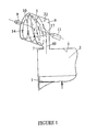
- the piston 1 moves upwardly as drawn in cylinder 2 during the compression stroke.
- the combustion chamber 6 shown in this embodiment is cylindrical and communicates with cylinder 2 through transfer orifice 7.
- the fuel injector 11 delivers fuel across the air jet 40 towards the far end of the combustion chamber 10 where spark plug 9 is situated.
- the diagram also illustrates a streamline 14 rotating around the periphery 22 of the combustion chamber in helical swirl motion.
- Transfer orifice 7 enters the combustion chamber adjacent to its periphery in order to impart swirl to the air moving in the chamber and an inclined helical ramp situated at the near end of the chamber 8 (not shown) imparts a longitudinal velocity component to the air entering the chamber to promote helical swirl motion.
- Cylinder 2 communicates with inlet and exhaust valves (not shown) in known fashion.
- Controlling the timing of the start of fuel injection ensures that some of the fuel spray cone 17 reaches the far end of the combustion chamber 10 during the early part of the compression stroke before it is fully absorbed into the air jet 40 entering the combustion chamber through transfer orifice 7 because the magnitude of the air jet velocity and the air density are smaller at the start of the compression stroke and increase substantially towards the end of the compression stroke.
- this fuel reaches the far end 10 at the earlier part of the compression stroke it may be deposited on the wall there but it soon vaporises when the helical swirl air flow arrives at the far end with sufficient magnitude.
- a difficult practical problem associated with the invention of patent publications WO2005/052335 and W02007/080366 is the need to avoid wetting the spark plug with liquid fuel during the early part of the fuel injection process.
- Fuel injector 11 points directly at the spark plug 9 at the far end 10 making this unavoidable. After such wetting the spark plug electrodes soon become covered with carbon soot which conducts electricity and extinguishes the spark.
- Ignition pots are small cavities of a fixed volume, which contain the electrodes end of the spark plug and communicate with the combustion chamber through a hole.
- the communication hole was situated on the far end face of the combustion chamber 10 and was machined inclined to the axis of the combustion chamber to stop direct entry of fuel spray through this communication hole.
- the principle of the ignition pot is to allow gas, in this case air fuel mixture, to be compressed into the ignition pot cavity during the compression stroke. After ignition the burning gases emerge from the ignition pot cavity under pressure as a plasma or a flaming jet igniting the mixture outside.
- gas in this case air fuel mixture
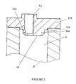
- Figure 2 illustrates the device invented to solve this problem. It is self evident that unless reliable spark ignition can be achieved with an engine according to the inventions described in patent publications W02005/052335 and W02007/080366 such engines cannot function reliably.
- end cap 212 is attached to the far end of the combustion chamber 6 by bolts (not shown), but the end cap can be made integral with the combustion chamber if desired.
- the end cap contains a screw threaded hole shown as 9A with a screw thread which secures the spark plug (not shown).
- the spark plug hole is shown eccentric to the axis of the combustion chamber to allow close proximity to the periphery.
- the end cap shown contains a cylindrical protrusion 209 which is substantially concentric with the combustion chamber and which projects into the combustion chamber over a short distance; it is shown with a bevelled free end as a preferred embodiment.
- the protrusion forms an annular groove 210 with the periphery of the combustion chamber. It has been found that the radial width of this annular groove is important for the operation of the device as it contains the swirling air fuel mixture which, during the compression stroke, is concentrated around the periphery of the chamber 22, under the influence of centrifugal force.
- the radial width of the annular groove will depend on the intensity of the helical swirl flow chosen by the designer to influence the speed of combustion and needs to be optimised for a given engine geometry.
- a slot 211 communicating between the spark plug electrodes and the groove 210.
- the spark plug electrodes are placed substantially opposite the slot.
- the slot can be made with a substantial length around the periphery of 209, for example four times its height, but is preferably placed around the thinnest wall between the eccentric spark plug hole 9A and annular groove 210, provided that incandescence is avoided. Spark plug hole 9A is placed in an eccentric position to the protrusion 209 in order to reduce the thickness of the wall around the slot 211.
- the present invention prevents liquid fuel from being directly deposited on the spark plug electrodes since the slot 211 is, in this embodiment, placed on a wall parallel with the axis of the combustion chamber. It also allows a generous opening between the spark plug electrodes and the rest of the combustion chamber to minimise the amount of products of combustion remain around the spark plug after ignition to upset the ignition of subsequent cycles.
- the spark plug electrodes can have a direct line of sight with the air fuel mixture rotating in annular groove 210.
- the present invention is crucially important since it allows the engine to operate reliably without spark malfunction. It is not an obvious solution to a man skilled in the art but is a result of substantial research and development on an engine test bed, it has been found to work extremely well.
Landscapes
- Engineering & Computer Science (AREA)
- Chemical & Material Sciences (AREA)
- Combustion & Propulsion (AREA)
- Mechanical Engineering (AREA)
- General Engineering & Computer Science (AREA)
- Combustion Methods Of Internal-Combustion Engines (AREA)
- Ignition Installations For Internal Combustion Engines (AREA)
- Cylinder Crankcases Of Internal Combustion Engines (AREA)
Claims (5)
- Un moteur à combustion interne comportant
un piston coulissant dans un cylindre ;
un moyen d'admission d'air communiquant avec le cylindre ;
un moyen d'échappement communiquant avec le cylindre ;
une chambre de combustion indirecte communiquant avec le cylindre comportant une extrémité proche et une extrémité éloignée relativement au piston ;
un orifice de transfert communiquant avec le cylindre et la chambre de combustion au niveau de son extrémité proche ;
un moyen pour promouvoir un déplacement d'air à l'intérieur de la chambre de combustion dans un mouvement de tourbillon hélicoïdal ayant un composant de vitesse tangentielle autour de la chambre de combustion et un composant de vitesse axiale le long de la chambre de combustion, le composant de vitesse axiale étant dirigé à l'écart de l'extrémité proche et en direction de l'extrémité éloignée ;
au moins un injecteur de carburant communiquant avec la chambre de combustion ; un contrôleur pour contrôler le processus d'injection de carburant et l'événement d'allumage par étincelle ;
un moyen d'allumage par étincelle communiquant avec la chambre de combustion au niveau de son extrémité éloignée ;
caractérisé en ce que l'extrémité éloignée de la chambre de combustion a une saillie substantiellement concentrique dans la chambre faisant face à l'extrémité proche qui forme une rainure annulaire avec la périphérie de la chambre de combustion, la saillie contient un trou pour une bougie d'allumage qui communique avec ladite rainure à travers une ouverture permettant à l'étincelle d'être exposée au mélange de carburant et d'air en rotation dans ladite rainure pour permettre un allumage par étincelle direct du mélange. - Un moteur selon la revendication 1 dans lequel l'ouverture a la forme d'une fente.
- Un moteur selon la revendication 1 dans lequel la saillie est cylindrique.
- Un moteur selon la revendication 1 et la revendication 3 dans lequel la saillie a un bord biseauté au niveau de son extrémité libre.
- Un moteur selon la revendication 1 dans lequel un injecteur de carburant délivre du carburant vers l'extrémité éloignée de la chambre de combustion.
Applications Claiming Priority (2)
| Application Number | Priority Date | Filing Date | Title |
|---|---|---|---|
| GBGB0712185.8A GB0712185D0 (en) | 2007-06-23 | 2007-06-23 | Internal combustion engine |
| PCT/GB2008/002060 WO2009001033A1 (fr) | 2007-06-23 | 2008-06-16 | Moteur à combustion interne |
Publications (2)
| Publication Number | Publication Date |
|---|---|
| EP2193263A1 EP2193263A1 (fr) | 2010-06-09 |
| EP2193263B1 true EP2193263B1 (fr) | 2013-02-13 |
Family
ID=38352786
Family Applications (1)
| Application Number | Title | Priority Date | Filing Date |
|---|---|---|---|
| EP08762384A Not-in-force EP2193263B1 (fr) | 2007-06-23 | 2008-06-16 | Moteur à combustion interne |
Country Status (8)
| Country | Link |
|---|---|
| US (1) | US8201540B2 (fr) |
| EP (1) | EP2193263B1 (fr) |
| JP (1) | JP5192037B2 (fr) |
| CN (1) | CN101688465B (fr) |
| BR (1) | BRPI0811695A8 (fr) |
| GB (1) | GB0712185D0 (fr) |
| RU (1) | RU2468220C2 (fr) |
| WO (1) | WO2009001033A1 (fr) |
Families Citing this family (3)
| Publication number | Priority date | Publication date | Assignee | Title |
|---|---|---|---|---|
| GB201520221D0 (en) * | 2015-11-17 | 2015-12-30 | Merritt Dan | Internal combustion engine |
| JP6373321B2 (ja) * | 2016-09-13 | 2018-08-15 | 日本特殊陶業株式会社 | 点火プラグ |
| US10753267B2 (en) * | 2018-01-26 | 2020-08-25 | Quest Engines, LLC | Method and apparatus for producing stratified streams |
Family Cites Families (18)
| Publication number | Priority date | Publication date | Assignee | Title |
|---|---|---|---|---|
| US2902011A (en) * | 1956-02-10 | 1959-09-01 | Daimler Benz Ag | Injection type internal combustion engine |
| JPS5119210A (en) * | 1974-08-08 | 1976-02-16 | Toyota Motor Co Ltd | Nainenkikanno fukunenshoshitsurenrakuko |
| CS212763B2 (en) * | 1975-05-22 | 1982-03-26 | Bosch Gmbh Robert | Internal combustion engine |
| US4124000A (en) * | 1976-11-03 | 1978-11-07 | General Motors Corporation | Mixed cycle stratified charge engine with ignition antechamber |
| DE2715943C2 (de) * | 1977-04-09 | 1986-08-14 | Robert Bosch Gmbh, 7000 Stuttgart | Brennkraftmaschine mit wenigstens einem Hauptbrennraum und einer Zündkammer |
| US4248192A (en) * | 1977-05-05 | 1981-02-03 | Lampard Robert D | Internal combustion engine and method of operation thereof with isolated combustion initiation |
| JPH07116991B2 (ja) * | 1986-12-24 | 1995-12-18 | ヤンマーディーゼル株式会社 | 副室式ガス機関の副室構造 |
| CZ279111B6 (en) * | 1989-12-06 | 1994-12-15 | Univ Coventry | Internal combustion engine |
| FR2662745B1 (fr) * | 1990-05-31 | 1992-09-11 | Melchior Technologie Snc | Perfectionnements aux moteurs alternatifs a combustion interne, du type a deux temps. |
| GB2246394B (en) * | 1990-07-23 | 1994-02-23 | Dan Merritt | An internal combustion engine. |
| DE4135135A1 (de) * | 1991-10-24 | 1993-04-29 | Theo Goepel | Selbstzuendende hubkolbenbrennkraftmaschine |
| BR9306653A (pt) * | 1992-07-02 | 1998-12-08 | Univ Coventry | Motor de combustão interna e processo de fazer funcionar o mesmo |
| JPH0630433U (ja) * | 1992-09-18 | 1994-04-22 | 三菱重工業株式会社 | ガスエンジンのトーチ点火装置 |
| US5307772A (en) * | 1992-12-16 | 1994-05-03 | Ford Motor Company | Redox catalysis of NOx in internal combustion engines |
| US5392744A (en) * | 1993-03-12 | 1995-02-28 | Chrysler Corporation | Precombustion chamber for a double overhead camshaft internal combustion engine |
| CA2348911A1 (fr) * | 1998-11-24 | 2000-06-02 | Dan Merritt | Moteur a combustion interne |
| EP1692376B8 (fr) * | 2003-11-19 | 2008-07-16 | Musi Engines Limited | Moteur a combustion interne |
| US7387103B2 (en) * | 2003-11-19 | 2008-06-17 | Dan Merritt | Internal combustion engine |
-
2007
- 2007-06-23 GB GBGB0712185.8A patent/GB0712185D0/en not_active Ceased
-
2008
- 2008-06-16 BR BRPI0811695A patent/BRPI0811695A8/pt not_active IP Right Cessation
- 2008-06-16 RU RU2009148140/06A patent/RU2468220C2/ru not_active IP Right Cessation
- 2008-06-16 JP JP2010512759A patent/JP5192037B2/ja not_active Expired - Fee Related
- 2008-06-16 CN CN2008800215167A patent/CN101688465B/zh not_active Expired - Fee Related
- 2008-06-16 EP EP08762384A patent/EP2193263B1/fr not_active Not-in-force
- 2008-06-16 WO PCT/GB2008/002060 patent/WO2009001033A1/fr not_active Ceased
- 2008-06-16 US US12/666,150 patent/US8201540B2/en not_active Expired - Fee Related
Also Published As
| Publication number | Publication date |
|---|---|
| GB0712185D0 (en) | 2007-08-01 |
| CN101688465B (zh) | 2012-12-12 |
| RU2009148140A (ru) | 2011-07-27 |
| BRPI0811695A8 (pt) | 2019-01-22 |
| US8201540B2 (en) | 2012-06-19 |
| JP2010530938A (ja) | 2010-09-16 |
| JP5192037B2 (ja) | 2013-05-08 |
| CN101688465A (zh) | 2010-03-31 |
| RU2468220C2 (ru) | 2012-11-27 |
| BRPI0811695A2 (pt) | 2015-03-31 |
| US20100236519A1 (en) | 2010-09-23 |
| EP2193263A1 (fr) | 2010-06-09 |
| WO2009001033A1 (fr) | 2008-12-31 |
Similar Documents
| Publication | Publication Date | Title |
|---|---|---|
| CN100398793C (zh) | 具有气体燃料喷射的内燃机 | |
| US8910612B2 (en) | Pre-chamber jet igniter and engine including combustion chamber employing the same | |
| US6595182B2 (en) | Direct fuel injection and ignition system for internal combustion engines | |
| US9803536B2 (en) | Auxiliary chamber type internal combustion engine | |
| US20160069250A1 (en) | Control valve for pre-combustion chamber assembly | |
| EP3012444B1 (fr) | Ensemble chambre de précombustion pour moteurs à combustion interne | |
| US9957936B2 (en) | Fuel gas feed and ignition apparatus for a gas engine | |
| JP5002566B2 (ja) | エンジン及びエンジン用点火プラグ | |
| JP4465186B2 (ja) | 分割された燃焼室を備えた内燃機関 | |
| CN105518274A (zh) | 用于以气体为燃料的内燃机的燃烧系统 | |
| EP3536923B1 (fr) | Moteur à gaz de type à chambre auxiliaire | |
| US9194288B2 (en) | High swirl engine | |
| EP3118433B1 (fr) | Ensemble chambre de précombustion pour moteurs à combustion interne | |
| US20160069251A1 (en) | Pressure-limiting device for pre-combustion chamber | |
| EP2935865B1 (fr) | Pointe d'une bougie d'allumage d'un moteur à combustion interne | |
| WO2022150757A1 (fr) | Système passif de combustion à mélange pauvre et à préchambre | |
| EP2193263B1 (fr) | Moteur à combustion interne | |
| KR20190035530A (ko) | 이중 연료 엔진을 위한 분사 노즐 및 이중 연료 엔진 | |
| JP2012149655A (ja) | エンジン及びエンジン用点火プラグ | |
| JP5486645B2 (ja) | 副室式エンジン | |
| EP3366900B1 (fr) | Moteur à gaz | |
| JP2015021391A (ja) | 内燃機関 | |
| JP5319823B2 (ja) | エンジン及びエンジン用点火プラグ | |
| RU2443899C2 (ru) | Адиабатическая система впрыска-воспламенения | |
| WO2024224808A1 (fr) | Moteur à gaz |
Legal Events
| Date | Code | Title | Description |
|---|---|---|---|
| PUAI | Public reference made under article 153(3) epc to a published international application that has entered the european phase |
Free format text: ORIGINAL CODE: 0009012 |
|
| 17P | Request for examination filed |
Effective date: 20100325 |
|
| AK | Designated contracting states |
Kind code of ref document: A1 Designated state(s): AT BE BG CH CY CZ DE DK EE ES FI FR GB GR HR HU IE IS IT LI LT LU LV MC MT NL NO PL PT RO SE SI SK TR |
|
| AX | Request for extension of the european patent |
Extension state: AL BA MK RS |
|
| DAX | Request for extension of the european patent (deleted) | ||
| GRAP | Despatch of communication of intention to grant a patent |
Free format text: ORIGINAL CODE: EPIDOSNIGR1 |
|
| GRAS | Grant fee paid |
Free format text: ORIGINAL CODE: EPIDOSNIGR3 |
|
| GRAA | (expected) grant |
Free format text: ORIGINAL CODE: 0009210 |
|
| AK | Designated contracting states |
Kind code of ref document: B1 Designated state(s): AT BE BG CH CY CZ DE DK EE ES FI FR GB GR HR HU IE IS IT LI LT LU LV MC MT NL NO PL PT RO SE SI SK TR |
|
| REG | Reference to a national code |
Ref country code: GB Ref legal event code: FG4D |
|
| REG | Reference to a national code |
Ref country code: AT Ref legal event code: REF Ref document number: 596630 Country of ref document: AT Kind code of ref document: T Effective date: 20130215 |
|
| REG | Reference to a national code |
Ref country code: IE Ref legal event code: FG4D |
|
| REG | Reference to a national code |
Ref country code: DE Ref legal event code: R096 Ref document number: 602008022123 Country of ref document: DE Effective date: 20130411 |
|
| REG | Reference to a national code |
Ref country code: AT Ref legal event code: MK05 Ref document number: 596630 Country of ref document: AT Kind code of ref document: T Effective date: 20130213 |
|
| REG | Reference to a national code |
Ref country code: NL Ref legal event code: VDEP Effective date: 20130213 |
|
| REG | Reference to a national code |
Ref country code: LT Ref legal event code: MG4D |
|
| PG25 | Lapsed in a contracting state [announced via postgrant information from national office to epo] |
Ref country code: BG Free format text: LAPSE BECAUSE OF FAILURE TO SUBMIT A TRANSLATION OF THE DESCRIPTION OR TO PAY THE FEE WITHIN THE PRESCRIBED TIME-LIMIT Effective date: 20130513 Ref country code: SE Free format text: LAPSE BECAUSE OF FAILURE TO SUBMIT A TRANSLATION OF THE DESCRIPTION OR TO PAY THE FEE WITHIN THE PRESCRIBED TIME-LIMIT Effective date: 20130213 Ref country code: IS Free format text: LAPSE BECAUSE OF FAILURE TO SUBMIT A TRANSLATION OF THE DESCRIPTION OR TO PAY THE FEE WITHIN THE PRESCRIBED TIME-LIMIT Effective date: 20130613 Ref country code: LT Free format text: LAPSE BECAUSE OF FAILURE TO SUBMIT A TRANSLATION OF THE DESCRIPTION OR TO PAY THE FEE WITHIN THE PRESCRIBED TIME-LIMIT Effective date: 20130213 Ref country code: NO Free format text: LAPSE BECAUSE OF FAILURE TO SUBMIT A TRANSLATION OF THE DESCRIPTION OR TO PAY THE FEE WITHIN THE PRESCRIBED TIME-LIMIT Effective date: 20130513 Ref country code: AT Free format text: LAPSE BECAUSE OF FAILURE TO SUBMIT A TRANSLATION OF THE DESCRIPTION OR TO PAY THE FEE WITHIN THE PRESCRIBED TIME-LIMIT Effective date: 20130213 Ref country code: ES Free format text: LAPSE BECAUSE OF FAILURE TO SUBMIT A TRANSLATION OF THE DESCRIPTION OR TO PAY THE FEE WITHIN THE PRESCRIBED TIME-LIMIT Effective date: 20130524 |
|
| PG25 | Lapsed in a contracting state [announced via postgrant information from national office to epo] |
Ref country code: SI Free format text: LAPSE BECAUSE OF FAILURE TO SUBMIT A TRANSLATION OF THE DESCRIPTION OR TO PAY THE FEE WITHIN THE PRESCRIBED TIME-LIMIT Effective date: 20130213 Ref country code: LV Free format text: LAPSE BECAUSE OF FAILURE TO SUBMIT A TRANSLATION OF THE DESCRIPTION OR TO PAY THE FEE WITHIN THE PRESCRIBED TIME-LIMIT Effective date: 20130213 Ref country code: PT Free format text: LAPSE BECAUSE OF FAILURE TO SUBMIT A TRANSLATION OF THE DESCRIPTION OR TO PAY THE FEE WITHIN THE PRESCRIBED TIME-LIMIT Effective date: 20130613 Ref country code: PL Free format text: LAPSE BECAUSE OF FAILURE TO SUBMIT A TRANSLATION OF THE DESCRIPTION OR TO PAY THE FEE WITHIN THE PRESCRIBED TIME-LIMIT Effective date: 20130213 Ref country code: FI Free format text: LAPSE BECAUSE OF FAILURE TO SUBMIT A TRANSLATION OF THE DESCRIPTION OR TO PAY THE FEE WITHIN THE PRESCRIBED TIME-LIMIT Effective date: 20130213 Ref country code: BE Free format text: LAPSE BECAUSE OF FAILURE TO SUBMIT A TRANSLATION OF THE DESCRIPTION OR TO PAY THE FEE WITHIN THE PRESCRIBED TIME-LIMIT Effective date: 20130213 Ref country code: GR Free format text: LAPSE BECAUSE OF FAILURE TO SUBMIT A TRANSLATION OF THE DESCRIPTION OR TO PAY THE FEE WITHIN THE PRESCRIBED TIME-LIMIT Effective date: 20130514 |
|
| PG25 | Lapsed in a contracting state [announced via postgrant information from national office to epo] |
Ref country code: HR Free format text: LAPSE BECAUSE OF FAILURE TO SUBMIT A TRANSLATION OF THE DESCRIPTION OR TO PAY THE FEE WITHIN THE PRESCRIBED TIME-LIMIT Effective date: 20130213 |
|
| PG25 | Lapsed in a contracting state [announced via postgrant information from national office to epo] |
Ref country code: SK Free format text: LAPSE BECAUSE OF FAILURE TO SUBMIT A TRANSLATION OF THE DESCRIPTION OR TO PAY THE FEE WITHIN THE PRESCRIBED TIME-LIMIT Effective date: 20130213 Ref country code: DK Free format text: LAPSE BECAUSE OF FAILURE TO SUBMIT A TRANSLATION OF THE DESCRIPTION OR TO PAY THE FEE WITHIN THE PRESCRIBED TIME-LIMIT Effective date: 20130213 Ref country code: CZ Free format text: LAPSE BECAUSE OF FAILURE TO SUBMIT A TRANSLATION OF THE DESCRIPTION OR TO PAY THE FEE WITHIN THE PRESCRIBED TIME-LIMIT Effective date: 20130213 Ref country code: RO Free format text: LAPSE BECAUSE OF FAILURE TO SUBMIT A TRANSLATION OF THE DESCRIPTION OR TO PAY THE FEE WITHIN THE PRESCRIBED TIME-LIMIT Effective date: 20130213 Ref country code: NL Free format text: LAPSE BECAUSE OF FAILURE TO SUBMIT A TRANSLATION OF THE DESCRIPTION OR TO PAY THE FEE WITHIN THE PRESCRIBED TIME-LIMIT Effective date: 20130213 Ref country code: EE Free format text: LAPSE BECAUSE OF FAILURE TO SUBMIT A TRANSLATION OF THE DESCRIPTION OR TO PAY THE FEE WITHIN THE PRESCRIBED TIME-LIMIT Effective date: 20130213 |
|
| PLBE | No opposition filed within time limit |
Free format text: ORIGINAL CODE: 0009261 |
|
| STAA | Information on the status of an ep patent application or granted ep patent |
Free format text: STATUS: NO OPPOSITION FILED WITHIN TIME LIMIT |
|
| PG25 | Lapsed in a contracting state [announced via postgrant information from national office to epo] |
Ref country code: IT Free format text: LAPSE BECAUSE OF FAILURE TO SUBMIT A TRANSLATION OF THE DESCRIPTION OR TO PAY THE FEE WITHIN THE PRESCRIBED TIME-LIMIT Effective date: 20130213 |
|
| 26N | No opposition filed |
Effective date: 20131114 |
|
| PG25 | Lapsed in a contracting state [announced via postgrant information from national office to epo] |
Ref country code: MC Free format text: LAPSE BECAUSE OF FAILURE TO SUBMIT A TRANSLATION OF THE DESCRIPTION OR TO PAY THE FEE WITHIN THE PRESCRIBED TIME-LIMIT Effective date: 20130213 |
|
| REG | Reference to a national code |
Ref country code: CH Ref legal event code: PL |
|
| REG | Reference to a national code |
Ref country code: DE Ref legal event code: R097 Ref document number: 602008022123 Country of ref document: DE Effective date: 20131114 |
|
| REG | Reference to a national code |
Ref country code: IE Ref legal event code: MM4A |
|
| PG25 | Lapsed in a contracting state [announced via postgrant information from national office to epo] |
Ref country code: IE Free format text: LAPSE BECAUSE OF NON-PAYMENT OF DUE FEES Effective date: 20130616 Ref country code: CH Free format text: LAPSE BECAUSE OF NON-PAYMENT OF DUE FEES Effective date: 20130630 Ref country code: LI Free format text: LAPSE BECAUSE OF NON-PAYMENT OF DUE FEES Effective date: 20130630 |
|
| PG25 | Lapsed in a contracting state [announced via postgrant information from national office to epo] |
Ref country code: MT Free format text: LAPSE BECAUSE OF FAILURE TO SUBMIT A TRANSLATION OF THE DESCRIPTION OR TO PAY THE FEE WITHIN THE PRESCRIBED TIME-LIMIT Effective date: 20130213 |
|
| PG25 | Lapsed in a contracting state [announced via postgrant information from national office to epo] |
Ref country code: CY Free format text: LAPSE BECAUSE OF FAILURE TO SUBMIT A TRANSLATION OF THE DESCRIPTION OR TO PAY THE FEE WITHIN THE PRESCRIBED TIME-LIMIT Effective date: 20130213 Ref country code: TR Free format text: LAPSE BECAUSE OF FAILURE TO SUBMIT A TRANSLATION OF THE DESCRIPTION OR TO PAY THE FEE WITHIN THE PRESCRIBED TIME-LIMIT Effective date: 20130213 |
|
| PG25 | Lapsed in a contracting state [announced via postgrant information from national office to epo] |
Ref country code: HU Free format text: LAPSE BECAUSE OF FAILURE TO SUBMIT A TRANSLATION OF THE DESCRIPTION OR TO PAY THE FEE WITHIN THE PRESCRIBED TIME-LIMIT; INVALID AB INITIO Effective date: 20080616 Ref country code: LU Free format text: LAPSE BECAUSE OF NON-PAYMENT OF DUE FEES Effective date: 20130616 |
|
| REG | Reference to a national code |
Ref country code: FR Ref legal event code: PLFP Year of fee payment: 9 |
|
| REG | Reference to a national code |
Ref country code: DE Ref legal event code: R081 Ref document number: 602008022123 Country of ref document: DE Owner name: MOTODAN LIMITED, COVENTRY, GB Free format text: FORMER OWNER: MUSI ENGINES LTD., STYVECHALE, COVENTRY, GB Ref country code: DE Ref legal event code: R082 Ref document number: 602008022123 Country of ref document: DE Representative=s name: PATENT- & RECHTSANWAELTE BAUER WAGNER PRIESMEY, DE |
|
| REG | Reference to a national code |
Ref country code: FR Ref legal event code: PLFP Year of fee payment: 10 |
|
| PGFP | Annual fee paid to national office [announced via postgrant information from national office to epo] |
Ref country code: DE Payment date: 20170630 Year of fee payment: 10 |
|
| REG | Reference to a national code |
Ref country code: DE Ref legal event code: R119 Ref document number: 602008022123 Country of ref document: DE |
|
| PG25 | Lapsed in a contracting state [announced via postgrant information from national office to epo] |
Ref country code: FR Free format text: LAPSE BECAUSE OF NON-PAYMENT OF DUE FEES Effective date: 20180630 Ref country code: DE Free format text: LAPSE BECAUSE OF NON-PAYMENT OF DUE FEES Effective date: 20190101 |
|
| PGFP | Annual fee paid to national office [announced via postgrant information from national office to epo] |
Ref country code: GB Payment date: 20210629 Year of fee payment: 14 |
|
| GBPC | Gb: european patent ceased through non-payment of renewal fee |
Effective date: 20220616 |
|
| PG25 | Lapsed in a contracting state [announced via postgrant information from national office to epo] |
Ref country code: GB Free format text: LAPSE BECAUSE OF NON-PAYMENT OF DUE FEES Effective date: 20220616 |