EP2193352B1 - System und verfahren zum bestimmen des korrekten anpressdrucks für eine pflanzmaschinen-reiheneinheit - Google Patents
System und verfahren zum bestimmen des korrekten anpressdrucks für eine pflanzmaschinen-reiheneinheit Download PDFInfo
- Publication number
- EP2193352B1 EP2193352B1 EP08727400.7A EP08727400A EP2193352B1 EP 2193352 B1 EP2193352 B1 EP 2193352B1 EP 08727400 A EP08727400 A EP 08727400A EP 2193352 B1 EP2193352 B1 EP 2193352B1
- Authority
- EP
- European Patent Office
- Prior art keywords
- load
- sampling period
- margin
- occurrences
- calculated
- Prior art date
- Legal status (The legal status is an assumption and is not a legal conclusion. Google has not performed a legal analysis and makes no representation as to the accuracy of the status listed.)
- Active
Links
Images





Classifications
-
- A—HUMAN NECESSITIES
- A01—AGRICULTURE; FORESTRY; ANIMAL HUSBANDRY; HUNTING; TRAPPING; FISHING
- A01C—PLANTING; SOWING; FERTILISING
- A01C7/00—Sowing
- A01C7/20—Parts of seeders for conducting and depositing seed
- A01C7/201—Mounting of the seeding tools
- A01C7/205—Mounting of the seeding tools comprising pressure regulation means
-
- A—HUMAN NECESSITIES
- A01—AGRICULTURE; FORESTRY; ANIMAL HUSBANDRY; HUNTING; TRAPPING; FISHING
- A01B—SOIL WORKING IN AGRICULTURE OR FORESTRY; PARTS, DETAILS, OR ACCESSORIES OF AGRICULTURAL MACHINES OR IMPLEMENTS, IN GENERAL
- A01B63/00—Lifting or adjusting devices or arrangements for agricultural machines or implements
- A01B63/002—Devices for adjusting or regulating the position of tools or wheels
-
- A—HUMAN NECESSITIES
- A01—AGRICULTURE; FORESTRY; ANIMAL HUSBANDRY; HUNTING; TRAPPING; FISHING
- A01B—SOIL WORKING IN AGRICULTURE OR FORESTRY; PARTS, DETAILS, OR ACCESSORIES OF AGRICULTURAL MACHINES OR IMPLEMENTS, IN GENERAL
- A01B63/00—Lifting or adjusting devices or arrangements for agricultural machines or implements
- A01B63/02—Lifting or adjusting devices or arrangements for agricultural machines or implements for implements mounted on tractors
- A01B63/10—Lifting or adjusting devices or arrangements for agricultural machines or implements for implements mounted on tractors operated by hydraulic or pneumatic means
- A01B63/111—Lifting or adjusting devices or arrangements for agricultural machines or implements for implements mounted on tractors operated by hydraulic or pneumatic means regulating working depth of implements
-
- A—HUMAN NECESSITIES
- A01—AGRICULTURE; FORESTRY; ANIMAL HUSBANDRY; HUNTING; TRAPPING; FISHING
- A01B—SOIL WORKING IN AGRICULTURE OR FORESTRY; PARTS, DETAILS, OR ACCESSORIES OF AGRICULTURAL MACHINES OR IMPLEMENTS, IN GENERAL
- A01B63/00—Lifting or adjusting devices or arrangements for agricultural machines or implements
- A01B63/02—Lifting or adjusting devices or arrangements for agricultural machines or implements for implements mounted on tractors
- A01B63/10—Lifting or adjusting devices or arrangements for agricultural machines or implements for implements mounted on tractors operated by hydraulic or pneumatic means
- A01B63/111—Lifting or adjusting devices or arrangements for agricultural machines or implements for implements mounted on tractors operated by hydraulic or pneumatic means regulating working depth of implements
- A01B63/114—Lifting or adjusting devices or arrangements for agricultural machines or implements for implements mounted on tractors operated by hydraulic or pneumatic means regulating working depth of implements to achieve a constant working depth
-
- A—HUMAN NECESSITIES
- A01—AGRICULTURE; FORESTRY; ANIMAL HUSBANDRY; HUNTING; TRAPPING; FISHING
- A01C—PLANTING; SOWING; FERTILISING
- A01C7/00—Sowing
-
- A—HUMAN NECESSITIES
- A01—AGRICULTURE; FORESTRY; ANIMAL HUSBANDRY; HUNTING; TRAPPING; FISHING
- A01C—PLANTING; SOWING; FERTILISING
- A01C7/00—Sowing
- A01C7/20—Parts of seeders for conducting and depositing seed
- A01C7/201—Mounting of the seeding tools
- A01C7/203—Mounting of the seeding tools comprising depth regulation means
-
- Y—GENERAL TAGGING OF NEW TECHNOLOGICAL DEVELOPMENTS; GENERAL TAGGING OF CROSS-SECTIONAL TECHNOLOGIES SPANNING OVER SEVERAL SECTIONS OF THE IPC; TECHNICAL SUBJECTS COVERED BY FORMER USPC CROSS-REFERENCE ART COLLECTIONS [XRACs] AND DIGESTS
- Y10—TECHNICAL SUBJECTS COVERED BY FORMER USPC
- Y10S—TECHNICAL SUBJECTS COVERED BY FORMER USPC CROSS-REFERENCE ART COLLECTIONS [XRACs] AND DIGESTS
- Y10S111/00—Planting
- Y10S111/90—Methods of planting seeds and miscellaneous compositions
-
- Y—GENERAL TAGGING OF NEW TECHNOLOGICAL DEVELOPMENTS; GENERAL TAGGING OF CROSS-SECTIONAL TECHNOLOGIES SPANNING OVER SEVERAL SECTIONS OF THE IPC; TECHNICAL SUBJECTS COVERED BY FORMER USPC CROSS-REFERENCE ART COLLECTIONS [XRACs] AND DIGESTS
- Y10—TECHNICAL SUBJECTS COVERED BY FORMER USPC
- Y10S—TECHNICAL SUBJECTS COVERED BY FORMER USPC CROSS-REFERENCE ART COLLECTIONS [XRACs] AND DIGESTS
- Y10S111/00—Planting
- Y10S111/903—Monitor
Definitions
- Varying soil conditions result from differing soil types (sand, clay, or silt), differences in soil moisture, drainage and tillage practices or conditions throughout the field. In addition to varying soil conditions, different operating speeds may require different adjustments to be made to the equipment.
- the downforce applied to the planter row unit One operating parameter over which the operator has the most control for adjusting to varying soil conditions is the downforce applied to the planter row unit.
- the first problem is that excess downforce results in too much weight being carried by the depth regulating member (i.e., depth gauge wheels, skis, skids, runners etc.). Excessive weight can compact the soil surrounding the furrow and thereby inhibit proper development and growth of the roots and plant. Excessive downforce can also result in a planting depth that is too great with some types of furrow openers.
- the second problem is that insufficient downforce can result in a shallow furrow which can also detrimentally effect the yield as the seed may not be deep enough to have adequate moisture for proper germination.
- the total downforce acting on the row unit consists of the dead weight of the row unit plus the live weight of seed and/or insecticide carried upon the row unit, plus any supplemental downforce applied through the parallel arm linkage.
- the majority is used in forcing the opener disk(s) into the soil to the desired seeding depth. The remainder of the total down force is carried by the depth gauge wheels.
- the Duello '999 Patent also suggests that some "change limit" must be exceeded before action is taken. Although it is unclear from the Duello specification, it is assumed that this change limit is a predetermined amount by which the load must change relative to the average before any action is to be taken.
- Jenson '857 discloses a depth control device that also measures the load on the gauge wheels where "readings are averaged and sampled every few seconds so as not to create an erratic reading.”
- Jenson '857 speaks of a desired or predetermined load value (target load) input by the operator.
- a control algorithm regulates the downforce in an attempt to ensure the average downforce matches the target load as closely as possible.
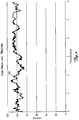
- FIG. 2 illustrates the load signal generated from actual planting conditions in a field which was highly tilled and had a uniform soil type.
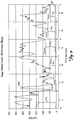
- FIG. 3 illustrates the load signal from a minimum tillage field where the load was varying dramatically.
- the average load was approximately 68 kilograms (150 pounds) but dropped nearly to zero and rose as high as 136 kilograms (300 pounds) at times.
- the proper downforce for any given planting condition should be that amount of downforce required to maintain the desired furrow depth without imparting excessive compaction to the soil surrounding the furrow. Balancing these two criteria is difficult because, as explained above, minimizing compaction will tend to create a loss of furrow depth, whereas minimizing loss of furrow depth will tend to increase compaction. Accordingly, there is a need for a system and method for determining the proper downforce for planter row units that will ensure desired furrow depth while minimizing soil compaction.
- the present invention provides a method as defined in claim 1. Preferred features of the method are the subject of claims 2 to 23.
- FIG. 1 illustrates a typical row unit 10 of a conventional planter such as the type disclosed in US Patent No. 4,009,668 .
- the row unit 10 is supported from the planter frame or toolbar 12 by a parallel arm linkage 14 extending between the toolbar 12 and the row unit frame 16.
- a dead load indicated by arrow 18 represents the dead load of the entire row unit, including the mass of the opener disk assembly 20 (including opener discs 41 and gauge wheels 42), frame 16, seed hopper 22, insecticide hopper 24, seed meter and seed tube, and the mass of any other attachments or devices supported by the row unit frame 16.
- a live load corresponding to the mass of the seed and insecticide stored within the hoppers 22, 24 are represented by arrows 26 and 28.
- a supplemental downforce 30 is also shown acting on the parallel arms 14.
- the supplemental downforce 30 may act in a manner to either increase or decrease the total or overall downforce carried by the gauge wheels 40.
- the supplemental down force 30 may be applied by any suitable biasing means, including mechanical springs, pneumatic cylinders, or through hydraulic cylinders 32 as shown in FIG. 1 .
- the dead load 18, the live loads 26, 28 and the supplemental downforce 30 is resisted by the reactionary forces exerted by the soil against the opener disk (opener disk load 38), the gauge wheels (the gauge wheel load 40) and the closing wheels (the closing wheel load 36).
- the depth adjustment mechanism 44 is used to set the relative distance between the bottom of the opener disks 41 and the bottom surface of the gauge wheels 42, thereby establishing the depth of penetration of the opener disks 41 into the soil surface.
- gauge wheels is used interchangeably throughout this specification with “depth regulation member.” Thus any recitation in this specification of such terms are to be understood as including any type of depth regulating member, whether gauge wheels, skis, skids, runners, etc. It is also assumed for purposes of this discussion that the opener disks 41 penetrate the soil to the desired predetermined depth set by the depth adjustment mechanism as long as the gauge wheel force 42 is greater than zero. If the gauge wheel force is zero or less, then it is assumed that the opener disks have not fully penetrated the soil to the desired preset depth.
- the present invention provides a novel method for determining the proper downforce for a planter row unit to ensure desired furrow depth while minimizing soil compaction under the depth regulating members.
- a load sensor is disposed on the row unit to generate a load signal corresponding to loading on a depth regulation member.
- FIGs. 2 and 3 are examples of actual tracings of load signals generated by such a load sensor.
- the preferred load sensor used to generate load signals corresponding to loading on a depth regulation member of the row unit is of the type disclosed in co-pending PCT Application WO 2008/086283 .
- any suitable means of generating load signals corresponding to loading on the depth regulating members of a row unit may be used in connection with the various methods of the present invention hereinafter described.
- the type of load sensors disclosed in Baker '901, Jensen '857, Duello '999 and/or as disclosed in US Provisional Application 60/883,957 filed January 8, 2007 may also be suitable.
- the total downforce on the row unit could be reduced by reducing the supplemental downforce 30 by approximately 36 kilograms (eighty pounds). Even with the reduction by 36 kilograms (eighty pounds), the resulting gauge wheel load 40 would never fall below approximately 2.3 kilograms (five pounds). Thus, it should be appreciated that an average load of approximately 9 kilograms (twenty pounds) would likely be more than sufficient to ensure desired furrow depth while minimizing soil compaction.
- the average load 100 is approximately 68 kilograms (150 pounds) but the low values are near zero.
- the supplemental downforce cannot be reduced without the gauge wheel load 40 reaching zero and thereby compromising depth control.
- these two load sensor tracings demonstrate that proper downforce on the row unit cannot be determined based on an average of the load values over a sampling period.
- the minimum value of the load signal occurring during a sampling period is detected (as opposed to the average load value as disclosed in Baker '901, Jensen '857, Duello '999). Based on this minimum load value a load margin is calculated which is indicative of the amount of supplemental downforce that should be added or subtracted (as the case may be) so that the downforce on the depth regulating member is proximate a desired minimum load threshold 104 (discussed later).
- FIG. 3 a load signal 100 spanning a time period of three seconds is illustrated.
- the load signal 100 has been broken into sampling periods ( t ) of approximately one-half second duration.
- sampling periods ( t ) For each sampling period ( t ), a minimum load value L min is identified.
- a minimum load threshold 104 is established either as a default value, an operator input parameter, or a parameter obtained from a GPS map of the field being planted.
- a margin (m) is calculated for each sampling period ( t ).
- the margin (m) represents the amount by which the supplemental downforce could be reduced while maintaining a load at least equal to the minimum load threshold 104 on the gauge wheels.
- the calculated load margin should be at or near zero, thereby ensuring desired furrow depth while minimizing soil compaction.
- the calculated load margin may be displayed to the operator, stored in memory for additional computation later, and/or if the planter is equipped to automatically adjust supplemental downforce.
- the minimum load threshold 104 is ideally a value slightly greater than zero in order to account for several factors.
- the preferred load sensor is of the type disclosed in PCT Application No. WO2008/086283 which utilizes a strain gauge. Strain gauges are subject to mechanical, thermal, and electrical drift over time such that a true zero load on the gauge wheels may result in a measured load of perhaps 2.3 kilograms (five pounds), for example. It is important to be able to determine whether the load on the gauge wheels has truly reached zero and thus a more reliable determination will be made if a minimum load threshold 104 is used which is greater than the amount of drift in the signal rather than comparing the signal to the value zero.
- a minimum gauge wheel load is generally desirable from an agronomic standpoint to ensure that the sidewalls of the furrow are firmed enough to remain open without collapsing until the seed has been placed in the furrow. Based on the foregoing factors, it has been found that a load threshold value 104 of about five pounds but less than about twenty pounds typically produces the desired results. However, the minimum load threshold may be higher or lower (nearly zero) as deemed necessary or appropriate based on operator experience and soil conditions.
- An alternative method of computing the load margin ( m ) takes into account the fact that a planter in operation is dynamic and that extremely short duration dips of the sensed gauge wheel load 40 do not necessarily mean that the row unit has lost desired furrow depth.
- the row unit travels a linear distance of 2.54 cm (one inch) in approximately eleven milliseconds.
- a row unit would have to travel dozens of millimeters (several inches) in order to make an appreciable change in depth of at least 3.2 mm (1/8 inch). It is known from experimental data that the accelerations on a typical planter row unit rarely exceed one g-force (9.8 m/sec 2 ) (32.2 ft/sec 2 ).
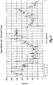
- FIG. 4 illustrates an alternative method for calculating load margin ( m ) where the minimum loads are defined as the minimum load value that is sustained for a time equal to or greater than T critical .
- the load margin ( m ) is then calculated as before by subtracting the load threshold 104 from the minimum load L min having a duration at least equal to T critical.
- FIG. 5 illustrates the same load signal trace as FIG. 3 .
- a forty millisecond low pass filter has been applied to the load signal 100.
- the load signal 100 is divided into one second sampling periods. The minimum value of the filtered signal within each sampling period is determined and then the margin (m) is calculated as the filtered minimum load L min minus the load threshold 104.
- This method results in improved control over the supplemental downforce as compared to other systems such as Duello '999 that filter the load signal to prevent overworking of the system while at the same time attempting to make control decisions of the supplemental downforce based upon the average load rather than the minimum load.
- a statistical analysis of the monitored load signal may be employed to derive or infer a load margin that is indicative of whether supplemental downforce on the row unit should be increased or decreased so that, statistically, the desired furrow depth is ensured while minimizing soil compaction.
- FIG. 6 the same load signal trace as in FIG. 3 is illustrated. However, rather than the 1/2 second sampling periods identified in FIG. 3 , FIG. 6 is intended to illustrate three one-second sampling periods, with each one-second sampling period divided into 100 millisecond time intervals.
- the average of the load signal during a sampling period (e.g., one second) is first determined by storing into a buffer or other system memory the actual load values detected during each preset time interval (e.g., every 100 milliseconds).
- the average load for the sampling period is then calculated by adding the actual load values detected during that sampling period and dividing that sum by the number of time intervals that comprise the sampling period (which, using the foregoing examples, would be ten time intervals per the one second sampling period).
- the standard deviation of the load values comprising the monitored load signal 100 over the sampling period is then determined.
- a deviation factor is defined either by default or as an operator configurable parameter.
- the deviation factor represents the number of multiples or units of the standard deviation away from the calculated average load value for the sampling period that is desired to be used for calculating the margin (m) . It has been found that a deviation factor having a value between about one and about five will give acceptable results, but a value of around 2.5 is a preferred deviation factor.
- the margin (m) derived using the foregoing statistical analysis is indicative of the amount of supplemental downforce on the row unit.
- the supplemental downforce should be increased or decreased accordingly, to bring the derived load margin toward zero thereby ensuring desired furrow depth while minimizing soil compaction.
- a pass may be defined as the period beginning with the planter being lowered into working position at one end of the field until it is raised at the other end of the field to permit the operator to turn around for a new pass.
- a pass may be defined as traveling from one point in a field to another.
- one method for excluding these load signal spikes while utilizing a statistical analysis to derive or infer a load margin is by applying a confidence factor to the load signals.
- the confidence factor preferably corresponds to the percent of time that the operator wants to ensure full furrow depth.
- the confidence factor preferably is between 95% and 99.9%.
- a default confidence factor of 99% is preferably assumed, but other values may be selected based on field conditions and operator experience. It should be understood that if a confidence factor of 100% is used, then the occasional soil irregularities that are encountered that cause sharp dips or negative spikes in the load signal will dominate the downforce setting for the entire pass or for whatever time span is being used for deciding when to adjust the supplemental downforce.
- a sampling period is presumed to be one second with each one-second sampling period divided into 100 millisecond time intervals.
- the time span for which this method is to be used is preferably the amount of time to equal a pass, but may be any longer or shorter time period. In this example a time span of three minutes (i.e., 180 seconds) is assumed.
- an average of the load signal is calculated for each sampling period (i.e., every one second period).
- the actual load values detected during each preset time interval i.e., every 100 milliseconds
- the load values detected during the sampling period are then added and the sum is divided by the number of time intervals that comprise the sampling period (which, in this example, is ten time intervals per one second sampling period).
- the average calculated load values for each sampling period comprising the time span are stored in memory for later retrieval.
- the calculated average load values are then retrieved from memory and ordered by magnitude.
- a number of calculated average load values are ordered by magnitude along the horizontal axis.
- the number of ordered calculated average load values are counted from left to right (i.e., beginning with the lowest magnitude) until the ignore count is reached.
- the load margin that is the next lowest in magnitude after reaching the ignore count is selected as the load margin. Referring to FIG. 7 , the first nine calculated average load values beginning from the left are ignored. Thus, the derived load margin will be about 24 kg (52 pounds) (i.e., the next lowest calculated average load value after meeting the ignore count of 5).
- the derived load margin will be 8.6 kg (19 pounds) (i.e., the next lowest calculated average load value after meeting the ignore count of 2).
- an average of the load signal is again calculated for each sampling period (i.e., every one second period).
- the actual load values for each preset time interval i.e., every 100 milliseconds
- the detected load values are added and the sum is divided by the number of time intervals that comprise the sampling period (i.e., ten time intervals per one second sampling period).
- the average calculated load values for each sampling period are stored in memory for later retrieval.
- the load margin scale is divided into substantially equal increments of load value magnitude ranges, for example ten pound increment ranges, such that the first increment is a magnitude range from 0 to 10 pounds, the second increment is from 10 to 20 pounds, the third increment is from 20 to 30 pounds, etc. through the increment of 64 to 68 kg (140 to 150 pounds).
- the load value magnitude ranges and the scale may vary as needed depending on the anticipated load margins and the precision of the load margin desired.
- the calculated averages are then sorted among the load value magnitude ranges. For example, referring to FIG. 8 , there was only one occurrence of a calculated load average of ten pounds during the entire time span.
- the derived load margin would be 40.8 kg (90 pounds) (i.e., the next incremental load value magnitude after ignoring nine occurrences).
- the load margin (calculated or derived by any of the foregoing methods) is preferably displayed to the operator.
- the load margin may be displayed simply as a numerical value and/or graphically, such as by a bar graph or up/down arrows, or the like.
- the numeric or graphical display of the load margin may also utilize a color scheme whereby certain colors are associated with different magnitudes. For example, if the load margin is within an acceptable range, the displayed color may be green. If the load margin is slightly outside the desired range, but still within acceptable limits, the displayed color may be yellow. If, however, the load margin is outside acceptable limits, the displayed color may be red. Any combination of the foregoing may be utilized, such as a colored bar, colored up or down arrows, colored numerical values, etc.
- ground contact percentages An additional parameter that can provide further confidence to the operator that adequate depth is being maintained while minimizing soil compaction is by monitoring ground contact percentages. For example, if the ground contact percentage is high (e.g., above 95%), then it may be presumed that adequate but not excess supplemental downforce is being exerted on the row unit to ensure that the desired furrow depth is being maintained. However, if the ground contact percentage is low (e.g., less than 90%), it may be presumed that the supplemental downforce being exerted is inadequate to ensure the desired furrow depth. Of course the desired ground contact percentages that different operators consider to be indicative of excess or inadequate supplement downforce may be vary. As such the ground contact percentage is preferably an operator selectable parameter.
- FIG. 9 illustrates a plot of a series of load values detected at two millisecond time intervals over a sampling period of 300 milliseconds, resulting in a total of 150 data points.
- a minimum preset load threshold 104 of twenty pounds is shown in relation to these 150 data points. Load values less than the minimum load threshold 104 are presumed to indicate a loss of ground contact, whereas load values greater than the minimum load threshold 104 indicate that ground contact was present or maintained.
- the percentage of ground contact can be easily calculated.
- the first set of load values that are below the minimum load threshold 104 occur during the sampling period between 35 and 96 milliseconds, and account for 21 data points.
- the second set of load values that are below the minimum load threshold 104 occur during the sampling period between 222 and 258 milliseconds and account for 13 data points.
- a total of 34 data points out of 150 data points are less than the minimum load threshold 104, resulting in a ground contact percentage of only 77.3% (i.e., (150-34) / 150). If the operator sees that the ground contact percentage is less than desired, then the operator can increase the downforce on the row unit by increasing the supplemental down force 30.
- the ground contact determination preferably utilizes the previously mentioned T critical duration of forty milliseconds, whereby, if the detected load value falls below the minimum load threshold 104 for less than T critical , the data points are not counted in the ground contact percentage calculation.
- T critical duration forty milliseconds
- the calculated ground contact percentage is 86% (i.e., (150-21) / 150).
- the supplemental downforce controller may be programmed to increase or decrease the supplemental downforce as needed to ensure that the ground contact percentage is at least equal to a desired ground contact percentage. It should be appreciated that while the foregoing example describes the ground contact parameter as a percentage, the ground contact parameter could instead be subtracted from 100% and the result could be reported instead as a "depth loss" parameter where 5% depth loss percentage is analogous to a ground contact percentage of 95%. Thus, for purposes of this description and the appended claims, any reference to ground contact parameter should be understood as also including or meaning depth loss or ground contact whether expressed as a percentage or any other form.
Landscapes
- Life Sciences & Earth Sciences (AREA)
- Soil Sciences (AREA)
- Environmental Sciences (AREA)
- Engineering & Computer Science (AREA)
- Mechanical Engineering (AREA)
- Management, Administration, Business Operations System, And Electronic Commerce (AREA)
- Transplanting Machines (AREA)
- Fertilizing (AREA)
- Lifting Devices For Agricultural Implements (AREA)
Claims (23)
- Verfahren zum Bestimmen, wann ergänzende Anpresskraft (30) auf einer Reiheneinheit (10) einer landwirtschaftlichen Pflanzmaschine angepasst werden soll, um eine gewünschte Ackerfurchentiefe sicherzustellen, während Bodenverdichtung minimiert wird, wobei das Verfahren die folgenden Schritte umfasst:(a) Anordnen eines Lastsensors zum Erzeugen eines Lastsignals (100), das der Last auf ein Tiefenregelelement (42) der Reiheneinheit entspricht;(b) Überwachen des erzeugten Lastsignals (100) zum Identifizieren eines minimalen Lastwerts, der während einer Abtastperiode auftritt; und(c) Berechnen einer Lastspanne (m) auf der Grundlage des minimalen Lastwerts.
- Verfahren nach Anspruch 1, wobei der minimale Lastwert ein Lastwert ist, der der kleinsten Signalgröße während der Abtastperiode entspricht.
- Verfahren nach Anspruch 1, wobei der minimale Lastwert ein Lastwert ist, der der kleinsten Signalgröße während der Abtastperiode, die eine Dauer von mindestens gleich einer kritischen Zeitdauer aufweist, entspricht.
- Verfahren nach Anspruch 1, wobei der minimale Lastwert ein Lastwert ist, der der kleinsten Signalgröße während der Abtastperiode, nach dem Anwenden eines Tiefpassfilters auf das überwachte Signal, entspricht.
- Verfahren nach Anspruch 2, 3 oder 4, wobei der Schritt des Berechnens einer Lastspanne (m) das Subtrahieren einer minimalen Lastschwelle (104) von dem minimalen Lastwert beinhaltet.
- Verfahren nach Anspruch 5, das ferner umfasst:(d) Anzeigen der berechneten Lastspanne (m) auf einer visuellen Anzeige.
- Verfahren nach Anspruch 5, das ferner umfasst:(d) Anpassen einer ergänzenden Anpresskraft (30), die auf die Reiheneinheit (10) wirkt, um die berechnete Lastspanne (m) auf null zu bringen.
- Verfahren nach Anspruch 7, wobei die minimale Lastschwelle (104) eine Bedienereingabe ist oder eine Eingabe, die über eine GPS-Landkartenschnittstelle empfangen wird.
- Verfahren nach Anspruch 1, das ferner umfasst:(d) Anzeigen der berechneten Lastspanne (m) auf einer visuellen Anzeige.
- Verfahren nach Anspruch 9, wobei die Anzeige der berechneten Lastspanne (m) eine graphische Anzeige der berechneten Lastspanne (m) ist.
- Verfahren nach Anspruch 10, wobei die graphische Anzeige eine Balkengraphik der berechneten Lastspanne (m) beinhaltet.
- Verfahren nach Anspruch 10 oder 11, wobei die graphische Anzeige ein Farbschema verwendet, in dem verschiedene vordefinierte Farben angezeigt werden, die vordefinierten Größenbereichen der berechneten Spanne entsprechen.
- Verfahren nach Anspruch 1, wobei der Schritt des Überwachens des erzeugten Lastsignals (100) ferner das Detektieren von Größen des erzeugten Lastsignals (100) in voreingestellten Zeitintervallen, die die Abtastperiode umfassen, beinhaltet.
- Verfahren nach Anspruch 13, das ferner die folgenden Schritte umfasst:(d) Berechnen eines Bodenkontaktparameters durch:(1) Identifizieren aufeinanderfolgender Auftritte, bei denen die detektierten Lastwerte kleiner als eine minimale Lastschwelle (104) sind, oder (2) Zählen der Auftritte der detektierten Lastwerte, die kleiner als eine minimale Lastschwelle (104) sind, und Dividieren der gezählten Auftritte durch die Anzahl von voreingestellten Zeitintervallen, die die Abtastperiode umfassen;(e) Bestimmen einer Dauer der identifizierten aufeinanderfolgenden Auftritte, bei denen die detektierten Lastwerte kleiner als die minimale Lastschwelle (104) sind;(f) Vergleichen der Dauer mit einer kritischen Zeitdauer;(g) Zählen aller Auftritte, die die identifizierten aufeinanderfolgenden Auftritte umfassen, bei denen die Dauer mindestens gleich der kritischen Zeitdauer ist;(h) Dividieren der gezählten Auftritte durch die Anzahl von voreingestellten Zeitintervallen, die die Abtastperiode umfassen.
- Verfahren nach Anspruch 14, das ferner umfasst:(i) Anzeigen des berechneten Bodenkontaktparameters als ein prozentualer Anteil auf einer visuellen Anzeige oder Anpassen einer ergänzenden Anpresskraft (30), die auf die Reiheneinheit (10) wirkt, so dass der berechnete Bodenkontaktparameter mindestens einen gewünschten minimalen Bodenkontaktparameter erfüllt.
- Verfahren nach Anspruch 1, wobei das Überwachen des erzeugten Lastsignals (100) das Detektieren einer Lastwertgröße in voreingestellten Zeitintervallen, die die Abtastperiode umfassen, beinhaltet.
- Verfahren nach Anspruch 16, das ferner Folgendes umfasst:(d) Definieren eines Abweichfaktors; undwobei der Schritt (c) des Ableitens der Lastspanne (m) folgende Schritte beinhaltet:(i) Berechnen eines durchschnittlichen Lastwerts für die Abtastperiode aus den detektierten Lastwerten in den voreingestellten Zeitintervallen;(ii) Berechnen einer Standardabweichung der detektierten Lastwerte während der Abtastperiode;(iii) Multiplizieren der Standardabweichung mit dem Abweichfaktor und Subtrahieren von dessen Produkt von dem berechneten durchschnittlichen Lastwert.
- Verfahren nach Anspruch 17, wobei der Abweichfaktor zwischen ungefähr eins und ungefähr fünf liegt.
- Verfahren nach Anspruch 16, das ferner Folgendes umfasst:(d) Definieren eines Konfidenzfaktors, wobei der Konfidenzfaktor, wenn er in Dezimalform dargestellt wird, kleiner als eins ist;wobei der Schritt (c) des Ableitens der Lastspanne (m) folgende Schritte beinhaltet:(i) für eine Zeitspanne, die eine voreingestellte Anzahl von Abtastperioden umfasst, Berechnen eines durchschnittlichen Lastwerts für jede der Abtastperioden aus den in den voreingestellten Zeitintervallen detektierten Lastwerten;(ii) Speichern des berechneten durchschnittlichen Lastwerts für jede Abtastperiode, die die Zeitspanne umfasst, in einem Speicher;(iii) Bestimmen einer Gesamtzahl der Abtastperiodenauftritte, die die Zeitspanne umfassen;(iv) Bestimmen einer Ignorierzahl durch Multiplizieren der Gesamtzahl der Abtastperiodenauftritte mit dem Konfidenzfaktor und Subtrahieren des Produkts von der Gesamtzahl von Abtastperiodenauftritten;(v) Ordnen der berechneten durchschnittlichen Lastwerte nach Größe;(vi) beginnend mit dem der Größe nach kleinsten der geordneten berechneten durchschnittlichen Lastwerte, Zählen in einer Richtung zunehmender Größe der Anzahl von geordneten berechneten durchschnittlichen Lastwerten bis die Zahl gleich der Ignorierzahl ist;(vii) Auswählen als die abgeleitete Lastspanne (m) des der Größe nach nächstkleinsten des geordneten berechneten durchschnittlichen Lastwerts, nachdem die Ignorierzahl erfüllt wurde.
- Verfahren nach Anspruch 16, das ferner Folgendes umfasst:(d) Definieren eines Konfidenzfaktors, wobei der Konfidenzfaktor, wenn er in Dezimalform dargestellt wird, kleiner als eins ist;wobei der Schritt des Ableitens der Lastspanne (m) folgende Schritte beinhaltet:(i) für eine Zeitspanne, die eine voreingestellte Anzahl von Abtastperioden umfasst, Berechnen eines durchschnittlichen Lastwerts für jede der Abtastperioden aus den in den voreingestellten Zeitintervallen detektierten Lastwerten;(ii) Bestimmen einer Gesamtzahl der Abtastperiodenauftritte, die die Zeitspanne umfassen;(iii) Definieren einer Skala für die Lastspanne (m), die in im Wesentlichen gleiche Inkremente von Lastwertgrößenbereichen aufgeteilt ist;(iv) Sortieren der Abtastperiodenauftritte der Größe nach durch Zuweisen jedes der berechneten durchschnittlichen Lastwerte zu einem entsprechenden der Inkrementallastwertgrößenbereiche der Skala für die Lastspanne (m);(v) Bestimmen einer Ignorierzahl durch Multiplizieren der Gesamtzahl der Abtastperiodenauftritte mit dem Konfidenzfaktor und Subtrahieren des Produkts von der Gesamtzahl von Abtastperiodenauftritten;(vi) beginnend mit einem der Größe nach kleinsten der Inkrementallastwertgrößenbereiche, in den mindestens einer der Abtastperiodenauftritte sortiert wurde, Zählen von jedem der sortierten Abtastperiodenauftritte innerhalb jedes der Inkrementallastwertgrößenbereiche bis die Zahl von Abtastperiodenauftritten gleich der Ignorierzahl ist;(vii) Auswählen als die abgeleitete Lastspanne (m) des der Größe nach nächstkleinsten der Inkrementallastwertgrößenbereiche, in den mindestens einer der Abtastperiodenauftritte sortiert wurde, nachdem die Ignorierzahl erfüllt wurde.
- Verfahren nach Anspruch 17, 19 oder 20, das ferner umfasst:(e) Anzeigen der abgeleiteten Lastspanne (m) auf einer visuellen Anzeige.
- Verfahren nach Anspruch 17, 19 oder 20, das ferner umfasst:(e) Anpassen einer ergänzenden Anpresskraft (30), die auf die Reiheneinheit (10) wirkt, um die abgeleitete Lastspanne (m) auf null zu bringen.
- Verfahren nach Anspruch 19 oder 20, wobei der Konfidenzfaktor zwischen ungefähr fünfundneunzig Prozent und neunundneunzig Prozent liegt.
Applications Claiming Priority (2)
| Application Number | Priority Date | Filing Date | Title |
|---|---|---|---|
| US97533207P | 2007-09-26 | 2007-09-26 | |
| PCT/US2008/050427 WO2009042238A1 (en) | 2007-09-26 | 2008-01-07 | System and method for determining proper downforce for a planter row unit |
Publications (3)
| Publication Number | Publication Date |
|---|---|
| EP2193352A1 EP2193352A1 (de) | 2010-06-09 |
| EP2193352A4 EP2193352A4 (de) | 2012-06-13 |
| EP2193352B1 true EP2193352B1 (de) | 2017-04-12 |
Family
ID=40511770
Family Applications (1)
| Application Number | Title | Priority Date | Filing Date |
|---|---|---|---|
| EP08727400.7A Active EP2193352B1 (de) | 2007-09-26 | 2008-01-07 | System und verfahren zum bestimmen des korrekten anpressdrucks für eine pflanzmaschinen-reiheneinheit |
Country Status (7)
| Country | Link |
|---|---|
| US (1) | US9173339B2 (de) |
| EP (1) | EP2193352B1 (de) |
| BR (1) | BRPI0817450B1 (de) |
| ES (1) | ES2627674T3 (de) |
| HU (1) | HUE034700T2 (de) |
| LT (1) | LT2193352T (de) |
| WO (1) | WO2009042238A1 (de) |
Families Citing this family (154)
| Publication number | Priority date | Publication date | Assignee | Title |
|---|---|---|---|---|
| US8359988B2 (en) | 2007-07-24 | 2013-01-29 | Dawn Equipment Company | Agricultural tillage device |
| BRPI0817450B1 (pt) | 2007-09-26 | 2018-12-18 | Prec Planting Inc | método de determinar quando ajustar a força descendente suplementar |
| US7673570B1 (en) | 2008-12-01 | 2010-03-09 | Dawn Equipment Company | Row-clearing unit for agricultural implement |
| US8327780B2 (en) | 2009-10-16 | 2012-12-11 | Dawn Equipment Company | Agricultural implement having fluid delivery features |
| US9968030B2 (en) | 2010-06-22 | 2018-05-15 | Cnh Industrial Canada, Ltd. | Down pressure adjustment device and method for use with a disc opener assembly of an agricultural implement |
| US9232687B2 (en) | 2010-09-15 | 2016-01-12 | Dawn Equipment Company | Agricultural systems |
| US8544397B2 (en) | 2010-09-15 | 2013-10-01 | Dawn Equipment Company | Row unit for agricultural implement |
| US9226440B2 (en) | 2010-09-15 | 2016-01-05 | Dawn Equipment Company | Agricultural apparatus with hydraulic cylinder and manifold for a row unit |
| US9055712B2 (en) | 2010-09-15 | 2015-06-16 | Dawn Equipment Company | Agricultural apparatus with integrated controller for a row unit |
| US8544398B2 (en) | 2010-09-15 | 2013-10-01 | Dawn Equipment Company | Hydraulic down pressure control system for closing wheels of an agricultural implement |
| US12389816B2 (en) | 2013-02-04 | 2025-08-19 | Deere & Company | Agricultural systems |
| US12171152B2 (en) | 2010-09-15 | 2024-12-24 | Deere & Company | System and method for adaptively controlling depth of ground-engaging planting row unit using forward sensor that measures residue ahead of row unit |
| US9107338B2 (en) | 2010-09-15 | 2015-08-18 | Dawn Equipment Company | Agricultural systems |
| US9107337B2 (en) | 2012-08-20 | 2015-08-18 | Dawn Equipment Company | Agricultural apparatus for sensing and providing feedback of soil property changes in real time |
| US8763713B2 (en) | 2012-01-27 | 2014-07-01 | Dawn Equipment Company | Agricultural implement with automatic down pressure control |
| US8776702B2 (en) | 2010-09-15 | 2014-07-15 | Dawn Equipment Company | Hydraulic down pressure control system for an agricultural implement |
| US8985232B2 (en) | 2012-08-20 | 2015-03-24 | Dawn Equipment Company | Agricultural apparatus for sensing and providing feedback of soil property changes in real time |
| US8634992B2 (en) | 2011-01-26 | 2014-01-21 | Precision Planting Llc | Dynamic supplemental downforce control system for planter row units |
| US8863857B2 (en) | 2011-02-23 | 2014-10-21 | Dawn Equipment Company | Row unit for agricultural implement |
| US8577561B2 (en) | 2011-03-08 | 2013-11-05 | Deere & Company | Control system and method of operating a product distribution machine |
| US8910582B2 (en) | 2011-04-11 | 2014-12-16 | Deere & Company | Row unit for a seeding machine having active downforce control for the closing wheels |
| EP2701482B1 (de) | 2011-04-27 | 2018-06-06 | Kinze Manufacturing, Inc. | System zur einstellung einer abwärts und/oder aufwärts wirkenden kraft |
| US9743578B2 (en) | 2011-04-27 | 2017-08-29 | Kinze Manufacturing, Inc. | Agricultural devices, systems, and methods for determining soil and seed characteristics and analyzing the same |
| US8909436B2 (en) | 2011-04-27 | 2014-12-09 | Kinze Manufacturing, Inc. | Remote adjustment of a row unit of an agricultural device |
| US10327374B2 (en) | 2011-04-27 | 2019-06-25 | Kinze Manufacturing, Inc. | Remote adjustment of a row unit of an agricultural device |
| US8935986B2 (en) | 2011-04-27 | 2015-01-20 | Kinze Manufacturing, Inc. | Agricultural devices, systems, and methods for determining soil and seed characteristics and analyzing the same |
| ES2803227T3 (es) | 2011-06-03 | 2021-01-25 | Prec Planting Llc | Aparato, sistemas y métodos para barra portaaperos agrícola |
| US8903545B2 (en) * | 2011-06-10 | 2014-12-02 | Great Plains Manufacturing, Inc. | Agricultural implement having hopper weighing system |
| US9271437B2 (en) | 2011-07-01 | 2016-03-01 | Charles H. Martin | Agricultural field preparation device |
| UA110988C2 (uk) | 2011-08-05 | 2016-03-10 | Пресіжн Плентінг Елелсі | Пристрій, системи і способи регулювання притискної сили рядного висівного апарата |
| WO2013112929A2 (en) | 2012-01-25 | 2013-08-01 | Precision Planting Llc | Agricultural toolbar apparatus, systems, and methods |
| US8636077B2 (en) | 2012-05-22 | 2014-01-28 | Dawn Equipment Company | Agricultural tool with structural housing for hydraulic actuator |
| US8380356B1 (en) | 2012-06-12 | 2013-02-19 | Ag Leader Technology | Seeder downforce section control |
| US9307690B2 (en) | 2012-06-14 | 2016-04-12 | Dawn Equipment Company | Forged toothed wheel for a row crop planter |
| RU2600182C2 (ru) * | 2012-06-28 | 2016-10-20 | Кинз Мэньюфэкчеринг, Инк. | Система распределения массы для семенных сеялок и машин для внесения продуктов |
| US8910581B2 (en) | 2012-07-25 | 2014-12-16 | Dawn Equipment Company | Side dressing fertilizer coulter |
| LT3729933T (lt) | 2012-07-25 | 2022-04-11 | Precision Planting Llc | Žemės ūkio padargo prispaudimo jėgos reguliavimo sistema |
| WO2014066650A1 (en) | 2012-10-24 | 2014-05-01 | Precision Planting Llc | Agricultural trench closing systems, methods, and apparatus |
| US9192091B2 (en) | 2013-02-01 | 2015-11-24 | Dawn Equipment Company | Agricultural apparatus with hybrid single-disk, double-disk coulter arrangement |
| US9215838B2 (en) | 2013-02-01 | 2015-12-22 | Dawn Equipment Company | Agricultural apparatus with hybrid single-disk, double-disk coulter arrangement |
| US9629304B2 (en) * | 2013-04-08 | 2017-04-25 | Ag Leader Technology | On-the go soil sensors and control methods for agricultural machines |
| US9668398B2 (en) | 2014-02-05 | 2017-06-06 | Dawn Equipment Company | Agricultural system for field preparation |
| US9241438B2 (en) | 2014-02-05 | 2016-01-26 | Dawn Equipment Company | Agricultural system for field preparation |
| US10721855B2 (en) | 2014-02-05 | 2020-07-28 | Dawn Equipment Company | Agricultural system for field preparation |
| US9615497B2 (en) | 2014-02-21 | 2017-04-11 | Dawn Equipment Company | Modular autonomous farm vehicle |
| US9565802B2 (en) * | 2014-05-20 | 2017-02-14 | Deere & Company | Crop sensing system and method with immediate gap detection |
| US11197411B2 (en) | 2014-11-07 | 2021-12-14 | Dawn Equipment Company | Agricultural planting system with automatic depth control |
| US10444774B2 (en) | 2014-11-07 | 2019-10-15 | Dawn Equipment Company | Agricultural system |
| US10582653B2 (en) | 2014-11-07 | 2020-03-10 | Dawn Equipment Company | Agricultural planting system with automatic depth control |
| US9848522B2 (en) | 2014-11-07 | 2017-12-26 | Dawn Equipment Company | Agricultural system |
| US9723778B2 (en) | 2014-11-07 | 2017-08-08 | Dawn Equipment Company | Agricultural system |
| US9826677B2 (en) | 2014-12-16 | 2017-11-28 | Cnh Industrial Canada, Ltd. | Seed implement incorporating a down pressure sensing and adjustment system |
| US9675004B2 (en) | 2015-09-30 | 2017-06-13 | Deere & Company | Soil moisture-based planter downforce control |
| US10980174B2 (en) | 2015-12-28 | 2021-04-20 | Underground Agriculture, LLC | Agricultural mowing device |
| US10477760B2 (en) | 2015-12-28 | 2019-11-19 | Underground Agriculture, LLC | Agricultural organic device for weed control |
| US11083134B2 (en) | 2015-12-28 | 2021-08-10 | Underground Agriculture, LLC | Agricultural inter-row mowing device |
| ES2922299T3 (es) | 2016-10-20 | 2022-09-13 | Prec Planting Llc | Control de fuerza de rueda de presión y de rueda de cierre de sembradora neumática |
| US10561056B2 (en) | 2017-04-28 | 2020-02-18 | Cnh Industrial America Llc | System and method for monitoring soil conditions within a field |
| US11259454B2 (en) * | 2017-04-28 | 2022-03-01 | Cnh Industrial America Llc | System and method for detecting ground engaging tool float for an agricultural implement |
| US11006563B2 (en) | 2017-05-04 | 2021-05-18 | Dawn Equipment Company | Seed firming device for improving seed to soil contact in a planter furrow with feature designed to prevent the buildup of soil on the outer surfaces by discharging pressurized fluid |
| US10645865B2 (en) | 2017-05-04 | 2020-05-12 | Dawn Equipment Company | Agricultural row unit with automatic control system for furrow closing device |
| US10548260B2 (en) | 2017-05-04 | 2020-02-04 | Dawn Equipment Company | System for automatically setting the set point of a planter automatic down pressure control system with a seed furrow sidewall compaction measurement device |
| UA125616C2 (uk) * | 2017-05-26 | 2022-05-04 | Пресіжн Плантінг Ллк | Спосіб запобігання зміщенню сільськогосподарського знаряддя |
| US10952362B2 (en) | 2017-06-30 | 2021-03-23 | Deere & Company | Dual basket attachment |
| US11224153B2 (en) | 2017-07-28 | 2022-01-18 | Kinze Manufacturing, Inc. | Agricultural implement and row units including double acting actuator systems, methods, and apparatus |
| US11122731B2 (en) | 2017-10-31 | 2021-09-21 | Deere & Company | Method of managing planter row unit downforce |
| WO2019118758A1 (en) * | 2017-12-15 | 2019-06-20 | Kinze Manufacturing, Inc. | Systems, methods, and apparatus for controlling downforce of an agricultural implement |
| US11277961B2 (en) | 2018-02-09 | 2022-03-22 | Ag Leader Technology | Seed spacing device for an agricultural planter and related systems and methods |
| US10813281B2 (en) | 2018-02-20 | 2020-10-27 | Ag Leader Technology | Apparatus, systems and methods for applying fluid |
| AU2019228022B2 (en) | 2018-03-01 | 2024-11-14 | Precision Planting Llc | Trench closing assembly |
| US20190297769A1 (en) | 2018-03-30 | 2019-10-03 | Ag Leader Technology | Devices, Systems, and Methods for Seed Trench Protection |
| US11246254B1 (en) | 2018-08-22 | 2022-02-15 | Parker-Hannifin Corporation | Negative downforce system for ground engaging machinery |
| US11178818B2 (en) | 2018-10-26 | 2021-11-23 | Deere & Company | Harvesting machine control system with fill level processing based on yield data |
| US11641800B2 (en) | 2020-02-06 | 2023-05-09 | Deere & Company | Agricultural harvesting machine with pre-emergence weed detection and mitigation system |
| US11672203B2 (en) | 2018-10-26 | 2023-06-13 | Deere & Company | Predictive map generation and control |
| US11467605B2 (en) | 2019-04-10 | 2022-10-11 | Deere & Company | Zonal machine control |
| US11957072B2 (en) | 2020-02-06 | 2024-04-16 | Deere & Company | Pre-emergence weed detection and mitigation system |
| US11240961B2 (en) | 2018-10-26 | 2022-02-08 | Deere & Company | Controlling a harvesting machine based on a geo-spatial representation indicating where the harvesting machine is likely to reach capacity |
| US11079725B2 (en) | 2019-04-10 | 2021-08-03 | Deere & Company | Machine control using real-time model |
| US11589509B2 (en) | 2018-10-26 | 2023-02-28 | Deere & Company | Predictive machine characteristic map generation and control system |
| US11653588B2 (en) | 2018-10-26 | 2023-05-23 | Deere & Company | Yield map generation and control system |
| US12069978B2 (en) | 2018-10-26 | 2024-08-27 | Deere & Company | Predictive environmental characteristic map generation and control system |
| US11477933B2 (en) | 2018-11-14 | 2022-10-25 | Cnh Industrial America Llc | Trench detection system for an agricultural implement |
| US12520744B2 (en) | 2018-11-15 | 2026-01-13 | Ag Leader Technology | On the go organic matter sensor and associated systems and methods |
| WO2020208442A1 (en) | 2019-04-09 | 2020-10-15 | Precision Planting Llc | Trench closing assembly |
| US11778945B2 (en) | 2019-04-10 | 2023-10-10 | Deere & Company | Machine control using real-time model |
| US11234366B2 (en) | 2019-04-10 | 2022-02-01 | Deere & Company | Image selection for machine control |
| CA3131355C (en) | 2019-05-03 | 2025-05-06 | Precision Planting Llc | WHEEL FOR CLOSING SYSTEM |
| US12414495B2 (en) | 2019-06-26 | 2025-09-16 | Precision Planting Llc | Scraper for trench closing assembly wheel |
| US11310953B2 (en) | 2019-07-02 | 2022-04-26 | Cnh Industrial America Llc | System and method for calibrating load sensors of an agricultural implement |
| US12329148B2 (en) | 2020-02-06 | 2025-06-17 | Deere & Company | Predictive weed map and material application machine control |
| US12035648B2 (en) | 2020-02-06 | 2024-07-16 | Deere & Company | Predictive weed map generation and control system |
| US12225846B2 (en) | 2020-02-06 | 2025-02-18 | Deere & Company | Machine control using a predictive map |
| US12268115B2 (en) | 2020-02-07 | 2025-04-08 | Ag Leader Technology | Planter obstruction monitoring and associated devices and methods |
| WO2021176280A1 (en) | 2020-03-04 | 2021-09-10 | Precision Planting Llc | Fluid applicator for trench closing assembly |
| US11477940B2 (en) | 2020-03-26 | 2022-10-25 | Deere & Company | Mobile work machine control based on zone parameter modification |
| US12557717B2 (en) | 2020-04-06 | 2026-02-24 | Precision Planting Llc | Row cleaner |
| US11849672B2 (en) | 2020-10-09 | 2023-12-26 | Deere & Company | Machine control using a predictive map |
| US20220110238A1 (en) | 2020-10-09 | 2022-04-14 | Deere & Company | Machine control using a predictive map |
| US12550802B2 (en) | 2020-10-08 | 2026-02-17 | Deere & Company | Predictive machine characteristic map generation and control system |
| US12013245B2 (en) | 2020-10-09 | 2024-06-18 | Deere & Company | Predictive map generation and control system |
| US11675354B2 (en) | 2020-10-09 | 2023-06-13 | Deere & Company | Machine control using a predictive map |
| US12422847B2 (en) | 2020-10-09 | 2025-09-23 | Deere & Company | Predictive agricultural model and map generation |
| US11849671B2 (en) | 2020-10-09 | 2023-12-26 | Deere & Company | Crop state map generation and control system |
| US11474523B2 (en) | 2020-10-09 | 2022-10-18 | Deere & Company | Machine control using a predictive speed map |
| US11727680B2 (en) | 2020-10-09 | 2023-08-15 | Deere & Company | Predictive map generation based on seeding characteristics and control |
| US11825768B2 (en) | 2020-10-09 | 2023-11-28 | Deere & Company | Machine control using a predictive map |
| US11844311B2 (en) | 2020-10-09 | 2023-12-19 | Deere & Company | Machine control using a predictive map |
| US11650587B2 (en) | 2020-10-09 | 2023-05-16 | Deere & Company | Predictive power map generation and control system |
| US11864483B2 (en) | 2020-10-09 | 2024-01-09 | Deere & Company | Predictive map generation and control system |
| US12386354B2 (en) | 2020-10-09 | 2025-08-12 | Deere & Company | Predictive power map generation and control system |
| US11874669B2 (en) | 2020-10-09 | 2024-01-16 | Deere & Company | Map generation and control system |
| US12419220B2 (en) | 2020-10-09 | 2025-09-23 | Deere & Company | Predictive map generation and control system |
| US11711995B2 (en) | 2020-10-09 | 2023-08-01 | Deere & Company | Machine control using a predictive map |
| US11946747B2 (en) | 2020-10-09 | 2024-04-02 | Deere & Company | Crop constituent map generation and control system |
| US11983009B2 (en) | 2020-10-09 | 2024-05-14 | Deere & Company | Map generation and control system |
| US11592822B2 (en) | 2020-10-09 | 2023-02-28 | Deere & Company | Machine control using a predictive map |
| US11927459B2 (en) | 2020-10-09 | 2024-03-12 | Deere & Company | Machine control using a predictive map |
| US12178158B2 (en) | 2020-10-09 | 2024-12-31 | Deere & Company | Predictive map generation and control system for an agricultural work machine |
| US11635765B2 (en) | 2020-10-09 | 2023-04-25 | Deere & Company | Crop state map generation and control system |
| US11871697B2 (en) | 2020-10-09 | 2024-01-16 | Deere & Company | Crop moisture map generation and control system |
| US11895948B2 (en) | 2020-10-09 | 2024-02-13 | Deere & Company | Predictive map generation and control based on soil properties |
| US11889788B2 (en) | 2020-10-09 | 2024-02-06 | Deere & Company | Predictive biomass map generation and control |
| US12069986B2 (en) | 2020-10-09 | 2024-08-27 | Deere & Company | Map generation and control system |
| US11845449B2 (en) | 2020-10-09 | 2023-12-19 | Deere & Company | Map generation and control system |
| US11889787B2 (en) | 2020-10-09 | 2024-02-06 | Deere & Company | Predictive speed map generation and control system |
| US12250905B2 (en) | 2020-10-09 | 2025-03-18 | Deere & Company | Machine control using a predictive map |
| US12477973B2 (en) | 2020-11-13 | 2025-11-25 | Ag Leader Technology | Agricultural high speed row unit |
| US12127500B2 (en) | 2021-01-27 | 2024-10-29 | Deere & Company | Machine control using a map with regime zones |
| US12082518B2 (en) | 2021-03-16 | 2024-09-10 | Cnh Industrial Canada, Ltd. | Location-based control system for an agricultural implement |
| EP4336992A1 (de) * | 2021-05-11 | 2024-03-20 | Precision Planting LLC | Reiheneinheiten einer luftsämaschine, sävorrichtungen und zugehörige verfahren |
| US12075721B2 (en) | 2021-05-27 | 2024-09-03 | Cnh Industrial Canada, Ltd. | Systems and methods for downforce control for an implement |
| WO2023004383A1 (en) | 2021-07-21 | 2023-01-26 | Kinze Manufacturing, Inc. | A row unit component for agricultural implements |
| US12310286B2 (en) | 2021-12-14 | 2025-05-27 | Deere & Company | Crop constituent sensing |
| US12302791B2 (en) | 2021-12-20 | 2025-05-20 | Deere & Company | Crop constituents, predictive mapping, and agricultural harvester control |
| US12484472B2 (en) | 2021-12-23 | 2025-12-02 | Cnh Industrial Canada, Ltd. | Penetration depth control and gauge wheel contact force monitoring system for an agricultural row unit |
| US12245549B2 (en) | 2022-01-11 | 2025-03-11 | Deere & Company | Predictive response map generation and control system |
| US12082531B2 (en) | 2022-01-26 | 2024-09-10 | Deere & Company | Systems and methods for predicting material dynamics |
| US12520759B2 (en) | 2022-01-26 | 2026-01-13 | Deere & Company | Systems and methods for predicting material dynamics |
| US12295288B2 (en) | 2022-04-05 | 2025-05-13 | Deere &Company | Predictive machine setting map generation and control system |
| US12298767B2 (en) | 2022-04-08 | 2025-05-13 | Deere & Company | Predictive material consumption map and control |
| US12358493B2 (en) | 2022-04-08 | 2025-07-15 | Deere & Company | Systems and methods for predictive power requirements and control |
| US12284934B2 (en) | 2022-04-08 | 2025-04-29 | Deere & Company | Systems and methods for predictive tractive characteristics and control |
| US12058951B2 (en) | 2022-04-08 | 2024-08-13 | Deere & Company | Predictive nutrient map and control |
| US12582035B2 (en) | 2022-04-08 | 2026-03-24 | Deere & Company | Systems and methods for predictive power requirements and control |
| US12336444B2 (en) | 2022-05-31 | 2025-06-24 | Cnh Industrial America Llc | Residue manager adjustment system and method |
| US12582024B2 (en) | 2022-08-31 | 2026-03-24 | Cnh Industrial Canada, Ltd. | Sensor drift detection for a downforce control system of a seeding implement |
| US12543615B2 (en) * | 2022-11-18 | 2026-02-10 | Deere & Company | Generating soil strength metric during row unit operation and controlling row unit |
| AU2023266361A1 (en) * | 2022-11-18 | 2024-06-06 | Stabilcorp Pty Ltd | Spreader assembly |
| US12457921B2 (en) | 2022-11-18 | 2025-11-04 | Deere & Company | Controlling components of row unit based on soil strength |
| EP4648603A1 (de) | 2023-01-13 | 2025-11-19 | Precision Planting LLC | Reihenreiniger |
| US12352294B2 (en) * | 2023-05-25 | 2025-07-08 | Parker Hannifin Corporation | Dual mode force control for surface engaging machinery |
| WO2026041919A1 (en) | 2024-08-20 | 2026-02-26 | Precision Planting Llc | Planter and row unit systems with integrated downforce control system |
| CN121605815A (zh) * | 2026-01-30 | 2026-03-06 | 辽宁省旱地农林研究所(辽宁省水土保持研究所、辽宁省干旱地区造林研究所) | 基于秸秆炭化微料与深松耕协同的褐土水稳团聚体构建方法 |
Family Cites Families (34)
| Publication number | Priority date | Publication date | Assignee | Title |
|---|---|---|---|---|
| CA930233A (en) * | 1968-12-10 | 1973-07-17 | Sweet Ralph | Automatic depth control device for tillage units |
| US4064945A (en) * | 1975-03-10 | 1977-12-27 | J. I. Case Company | Electronic depth control system |
| US4031963A (en) * | 1975-04-14 | 1977-06-28 | Erhard Poggemiller | Depth control device for ground working agricultural implements |
| US4009668A (en) * | 1975-07-07 | 1977-03-01 | Deere & Company | Planter apparatus and method for planting |
| US4176721A (en) * | 1976-11-30 | 1979-12-04 | Kep Enterprises | Depth control for ground working agricultural implements |
| DE2927585C2 (de) * | 1979-07-07 | 1983-06-09 | Xaver Fendt & Co, 8952 Marktoberdorf | Verfahren und Einrichtung zum Regeln der Arbeitstiefe eines von einer landwirtschaftlichen Zugmaschine, wie z.B. einem Schlepper getragenen Pfluges |
| US4413685A (en) * | 1979-12-11 | 1983-11-08 | Gremelspacher Philip E | Planter implement with adjusting position-display apparatus and system thereof |
| US4355688A (en) * | 1981-01-29 | 1982-10-26 | Deere & Company | Agricultural implement and depth control therefor |
| US4423788A (en) * | 1981-05-20 | 1984-01-03 | International Harvester Co. | Agricultural furrow forming apparatus depth control |
| US4522066A (en) * | 1982-05-13 | 1985-06-11 | Kistler-Morse Corporation | Temperature-compensated extensometer |
| US4461355A (en) * | 1982-06-01 | 1984-07-24 | Hiniker Company | Cultivator row unit with ridger/bedder implement |
| US4766962A (en) * | 1986-10-27 | 1988-08-30 | J. I. Case Company | Furrow forming apparatus for attachment to a tool bar |
| US4913070A (en) * | 1988-04-08 | 1990-04-03 | The United States Of America As Represented By The Secretary Of Agriculture | Ground contact implement soil penetration depth control |
| NZ227221A (en) | 1988-12-06 | 1992-11-25 | Univ Massey | Maintaining seed drill opener at constant depth by constantly monitoring soil reaction force on gauge wheel |
| US5163518A (en) * | 1991-08-21 | 1992-11-17 | Deere & Company | Down force adjustment and lift for an opener supported from a frame by lift arms |
| US5160055A (en) * | 1991-10-02 | 1992-11-03 | Jlg Industries, Inc. | Load moment indicator system |
| US5234060A (en) * | 1992-02-21 | 1993-08-10 | The United States Of America As Represnted By The Secretary Of Agriculture | Pressure and depth control in agricultural implement |
| US5348101A (en) * | 1993-01-08 | 1994-09-20 | Deere & Company | Hydraulic system for a towed implement |
| US5562165A (en) * | 1994-03-14 | 1996-10-08 | Universite Laval | Hydraulic floating system for downpressure control of seeding tools |
| US5544709A (en) * | 1995-04-17 | 1996-08-13 | Deere & Company | Down pressure spring adjustment |
| US6070539A (en) * | 1997-03-21 | 2000-06-06 | Case Corporation | Variable rate agricultural product application implement with multiple inputs and feedback |
| US6480808B1 (en) * | 1999-12-22 | 2002-11-12 | General Electric Company | Method and apparatus for calculating confidence intervals |
| US6460623B1 (en) * | 2000-10-20 | 2002-10-08 | Caterpillar Inc. | Hydraulic system providing down force on a work implement |
| US6823272B2 (en) * | 2001-10-23 | 2004-11-23 | Agilent Technologies, Inc. | Test executive system with progress window |
| US6389999B1 (en) * | 2001-11-02 | 2002-05-21 | Dennis Duello | Dynamic controller of excess downpressure for surface engaging implement |
| US6701857B1 (en) * | 2003-01-16 | 2004-03-09 | Lynn David Jensen | Depth control device for planting implement |
| US6827029B1 (en) * | 2003-11-04 | 2004-12-07 | Cnh America Llc | Method and apparatus for automatically maintaining seed trench depth during seed planting operations |
| US6935253B2 (en) * | 2003-11-07 | 2005-08-30 | Cnh America Llc | Depth control for seed planter |
| US6983705B1 (en) * | 2005-03-22 | 2006-01-10 | Cnh America Llc | Depth control mechanism |
| KR100730086B1 (ko) * | 2006-07-10 | 2007-06-19 | 삼성전기주식회사 | 듀얼 시스템 송수신장치 |
| WO2008008345A2 (en) | 2006-07-14 | 2008-01-17 | Martin Howard D | Apparatus for planter depth monitoring |
| US7360494B2 (en) * | 2006-07-14 | 2008-04-22 | Howard D. Martin | Apparatus for planter depth monitoring |
| US8078367B2 (en) * | 2007-01-08 | 2011-12-13 | Precision Planting, Inc. | Planter monitor system and method |
| BRPI0817450B1 (pt) | 2007-09-26 | 2018-12-18 | Prec Planting Inc | método de determinar quando ajustar a força descendente suplementar |
-
2008
- 2008-01-07 BR BRPI0817450A patent/BRPI0817450B1/pt active IP Right Grant
- 2008-01-07 WO PCT/US2008/050427 patent/WO2009042238A1/en not_active Ceased
- 2008-01-07 US US12/679,710 patent/US9173339B2/en active Active
- 2008-01-07 EP EP08727400.7A patent/EP2193352B1/de active Active
- 2008-01-07 ES ES08727400.7T patent/ES2627674T3/es active Active
- 2008-01-07 HU HUE08727400A patent/HUE034700T2/hu unknown
- 2008-01-07 LT LTEP08727400.7T patent/LT2193352T/lt unknown
Non-Patent Citations (1)
| Title |
|---|
| None * |
Also Published As
| Publication number | Publication date |
|---|---|
| WO2009042238A1 (en) | 2009-04-02 |
| LT2193352T (lt) | 2017-05-10 |
| HUE034700T2 (hu) | 2018-02-28 |
| ES2627674T3 (es) | 2017-07-31 |
| US20100198529A1 (en) | 2010-08-05 |
| BRPI0817450A2 (pt) | 2015-06-16 |
| EP2193352A4 (de) | 2012-06-13 |
| EP2193352A1 (de) | 2010-06-09 |
| US9173339B2 (en) | 2015-11-03 |
| BRPI0817450B1 (pt) | 2018-12-18 |
Similar Documents
| Publication | Publication Date | Title |
|---|---|---|
| EP2193352B1 (de) | System und verfahren zum bestimmen des korrekten anpressdrucks für eine pflanzmaschinen-reiheneinheit | |
| EP2104413B1 (de) | System und verfahren zur überwachung einer pflanzmaschine | |
| US11064651B2 (en) | Down pressure adjustment device and method for use with a disc opener assembly of an agricultural implement | |
| US6389999B1 (en) | Dynamic controller of excess downpressure for surface engaging implement | |
| EP3729941B1 (de) | Sämaschine mit furchenschliesser mit variabler kraft | |
| US11197411B2 (en) | Agricultural planting system with automatic depth control | |
| US20200128723A1 (en) | Soil sensing control devices, systems, and associated methods | |
| US8561472B2 (en) | Load sensing pin | |
| EP2554037B1 (de) | System für zusätzliche Anpresskraft, Bodenbearbeitungsgerät damit und Verfahren | |
| US20120125244A1 (en) | Mapping soil hardness | |
| EP2823700A1 (de) | Landwirtschaftliches Gerät und Verfahren zum Betrieb eines solchen | |
| EP4002984A1 (de) | Landwirtschaftliche geräte und pflanzverfahren | |
| US11229153B2 (en) | Load sensor bracket | |
| CA2784210C (en) | Tool control system for agricultural seeders | |
| EP3714671B1 (de) | Landwirtschaftliches pflanzsystem mit automatischer tiefenregelung | |
| CN112293027A (zh) | 基于花生联合收获机的多垄垄间距及单垄上下纬度调控装置 | |
| US12616078B2 (en) | Agricultural implements and methods of planting | |
| EP4252514A1 (de) | Pflanzmaschine zum pflanzen von setzlingen und entsprechendes verfahren zur steuerung des betriebs einer pflanzmaschine |
Legal Events
| Date | Code | Title | Description |
|---|---|---|---|
| PUAI | Public reference made under article 153(3) epc to a published international application that has entered the european phase |
Free format text: ORIGINAL CODE: 0009012 |
|
| 17P | Request for examination filed |
Effective date: 20100326 |
|
| AK | Designated contracting states |
Kind code of ref document: A1 Designated state(s): AT BE BG CH CY CZ DE DK EE ES FI FR GB GR HR HU IE IS IT LI LT LU LV MC MT NL NO PL PT RO SE SI SK TR |
|
| AX | Request for extension of the european patent |
Extension state: AL BA MK RS |
|
| DAX | Request for extension of the european patent (deleted) | ||
| A4 | Supplementary search report drawn up and despatched |
Effective date: 20120516 |
|
| RIC1 | Information provided on ipc code assigned before grant |
Ipc: G01N 3/42 20060101AFI20120510BHEP Ipc: A01C 7/20 20060101ALI20120510BHEP |
|
| RAP1 | Party data changed (applicant data changed or rights of an application transferred) |
Owner name: PLUM ACQUISITION SUB LLC, |
|
| RAP1 | Party data changed (applicant data changed or rights of an application transferred) |
Owner name: PRECISION PLANTING LLC |
|
| GRAP | Despatch of communication of intention to grant a patent |
Free format text: ORIGINAL CODE: EPIDOSNIGR1 |
|
| INTG | Intention to grant announced |
Effective date: 20161123 |
|
| GRAS | Grant fee paid |
Free format text: ORIGINAL CODE: EPIDOSNIGR3 |
|
| GRAA | (expected) grant |
Free format text: ORIGINAL CODE: 0009210 |
|
| RIN1 | Information on inventor provided before grant (corrected) |
Inventor name: KOCH, JUSTIN, L. Inventor name: BAUER, PHIL, D. Inventor name: SAUDER, TIM, A. Inventor name: SAUDER, DEREK, A. |
|
| RAP1 | Party data changed (applicant data changed or rights of an application transferred) |
Owner name: PRECISION PLANTING LLC |
|
| AK | Designated contracting states |
Kind code of ref document: B1 Designated state(s): AT BE BG CH CY CZ DE DK EE ES FI FR GB GR HR HU IE IS IT LI LT LU LV MC MT NL NO PL PT RO SE SI SK TR |
|
| REG | Reference to a national code |
Ref country code: GB Ref legal event code: FG4D |
|
| REG | Reference to a national code |
Ref country code: CH Ref legal event code: EP |
|
| REG | Reference to a national code |
Ref country code: IE Ref legal event code: FG4D |
|
| REG | Reference to a national code |
Ref country code: AT Ref legal event code: REF Ref document number: 884398 Country of ref document: AT Kind code of ref document: T Effective date: 20170515 |
|
| REG | Reference to a national code |
Ref country code: DE Ref legal event code: R096 Ref document number: 602008049713 Country of ref document: DE |
|
| REG | Reference to a national code |
Ref country code: RO Ref legal event code: EPE |
|
| REG | Reference to a national code |
Ref country code: ES Ref legal event code: FG2A Ref document number: 2627674 Country of ref document: ES Kind code of ref document: T3 Effective date: 20170731 |
|
| REG | Reference to a national code |
Ref country code: NL Ref legal event code: MP Effective date: 20170412 |
|
| PG25 | Lapsed in a contracting state [announced via postgrant information from national office to epo] |
Ref country code: NL Free format text: LAPSE BECAUSE OF FAILURE TO SUBMIT A TRANSLATION OF THE DESCRIPTION OR TO PAY THE FEE WITHIN THE PRESCRIBED TIME-LIMIT Effective date: 20170412 |
|
| PG25 | Lapsed in a contracting state [announced via postgrant information from national office to epo] |
Ref country code: HR Free format text: LAPSE BECAUSE OF FAILURE TO SUBMIT A TRANSLATION OF THE DESCRIPTION OR TO PAY THE FEE WITHIN THE PRESCRIBED TIME-LIMIT Effective date: 20170412 Ref country code: GR Free format text: LAPSE BECAUSE OF FAILURE TO SUBMIT A TRANSLATION OF THE DESCRIPTION OR TO PAY THE FEE WITHIN THE PRESCRIBED TIME-LIMIT Effective date: 20170713 Ref country code: NO Free format text: LAPSE BECAUSE OF FAILURE TO SUBMIT A TRANSLATION OF THE DESCRIPTION OR TO PAY THE FEE WITHIN THE PRESCRIBED TIME-LIMIT Effective date: 20170712 Ref country code: FI Free format text: LAPSE BECAUSE OF FAILURE TO SUBMIT A TRANSLATION OF THE DESCRIPTION OR TO PAY THE FEE WITHIN THE PRESCRIBED TIME-LIMIT Effective date: 20170412 |
|
| PG25 | Lapsed in a contracting state [announced via postgrant information from national office to epo] |
Ref country code: IS Free format text: LAPSE BECAUSE OF FAILURE TO SUBMIT A TRANSLATION OF THE DESCRIPTION OR TO PAY THE FEE WITHIN THE PRESCRIBED TIME-LIMIT Effective date: 20170812 Ref country code: LV Free format text: LAPSE BECAUSE OF FAILURE TO SUBMIT A TRANSLATION OF THE DESCRIPTION OR TO PAY THE FEE WITHIN THE PRESCRIBED TIME-LIMIT Effective date: 20170412 Ref country code: PL Free format text: LAPSE BECAUSE OF FAILURE TO SUBMIT A TRANSLATION OF THE DESCRIPTION OR TO PAY THE FEE WITHIN THE PRESCRIBED TIME-LIMIT Effective date: 20170412 Ref country code: SE Free format text: LAPSE BECAUSE OF FAILURE TO SUBMIT A TRANSLATION OF THE DESCRIPTION OR TO PAY THE FEE WITHIN THE PRESCRIBED TIME-LIMIT Effective date: 20170412 |
|
| REG | Reference to a national code |
Ref country code: DE Ref legal event code: R097 Ref document number: 602008049713 Country of ref document: DE |
|
| REG | Reference to a national code |
Ref country code: FR Ref legal event code: PLFP Year of fee payment: 11 |
|
| PG25 | Lapsed in a contracting state [announced via postgrant information from national office to epo] |
Ref country code: DK Free format text: LAPSE BECAUSE OF FAILURE TO SUBMIT A TRANSLATION OF THE DESCRIPTION OR TO PAY THE FEE WITHIN THE PRESCRIBED TIME-LIMIT Effective date: 20170412 Ref country code: EE Free format text: LAPSE BECAUSE OF FAILURE TO SUBMIT A TRANSLATION OF THE DESCRIPTION OR TO PAY THE FEE WITHIN THE PRESCRIBED TIME-LIMIT Effective date: 20170412 Ref country code: SK Free format text: LAPSE BECAUSE OF FAILURE TO SUBMIT A TRANSLATION OF THE DESCRIPTION OR TO PAY THE FEE WITHIN THE PRESCRIBED TIME-LIMIT Effective date: 20170412 |
|
| PLBE | No opposition filed within time limit |
Free format text: ORIGINAL CODE: 0009261 |
|
| STAA | Information on the status of an ep patent application or granted ep patent |
Free format text: STATUS: NO OPPOSITION FILED WITHIN TIME LIMIT |
|
| REG | Reference to a national code |
Ref country code: HU Ref legal event code: AG4A Ref document number: E034700 Country of ref document: HU |
|
| 26N | No opposition filed |
Effective date: 20180115 |
|
| PG25 | Lapsed in a contracting state [announced via postgrant information from national office to epo] |
Ref country code: SI Free format text: LAPSE BECAUSE OF FAILURE TO SUBMIT A TRANSLATION OF THE DESCRIPTION OR TO PAY THE FEE WITHIN THE PRESCRIBED TIME-LIMIT Effective date: 20170412 |
|
| REG | Reference to a national code |
Ref country code: CH Ref legal event code: PL |
|
| PG25 | Lapsed in a contracting state [announced via postgrant information from national office to epo] |
Ref country code: LU Free format text: LAPSE BECAUSE OF NON-PAYMENT OF DUE FEES Effective date: 20180107 |
|
| REG | Reference to a national code |
Ref country code: IE Ref legal event code: MM4A |
|
| REG | Reference to a national code |
Ref country code: BE Ref legal event code: MM Effective date: 20180131 |
|
| PG25 | Lapsed in a contracting state [announced via postgrant information from national office to epo] |
Ref country code: LI Free format text: LAPSE BECAUSE OF NON-PAYMENT OF DUE FEES Effective date: 20180131 Ref country code: CH Free format text: LAPSE BECAUSE OF NON-PAYMENT OF DUE FEES Effective date: 20180131 Ref country code: BE Free format text: LAPSE BECAUSE OF NON-PAYMENT OF DUE FEES Effective date: 20180131 |
|
| PG25 | Lapsed in a contracting state [announced via postgrant information from national office to epo] |
Ref country code: IE Free format text: LAPSE BECAUSE OF NON-PAYMENT OF DUE FEES Effective date: 20180107 |
|
| PG25 | Lapsed in a contracting state [announced via postgrant information from national office to epo] |
Ref country code: MC Free format text: LAPSE BECAUSE OF FAILURE TO SUBMIT A TRANSLATION OF THE DESCRIPTION OR TO PAY THE FEE WITHIN THE PRESCRIBED TIME-LIMIT Effective date: 20170412 |
|
| REG | Reference to a national code |
Ref country code: AT Ref legal event code: UEP Ref document number: 884398 Country of ref document: AT Kind code of ref document: T Effective date: 20170412 |
|
| PG25 | Lapsed in a contracting state [announced via postgrant information from national office to epo] |
Ref country code: MT Free format text: LAPSE BECAUSE OF NON-PAYMENT OF DUE FEES Effective date: 20180107 |
|
| PG25 | Lapsed in a contracting state [announced via postgrant information from national office to epo] |
Ref country code: TR Free format text: LAPSE BECAUSE OF FAILURE TO SUBMIT A TRANSLATION OF THE DESCRIPTION OR TO PAY THE FEE WITHIN THE PRESCRIBED TIME-LIMIT Effective date: 20170412 |
|
| PG25 | Lapsed in a contracting state [announced via postgrant information from national office to epo] |
Ref country code: PT Free format text: LAPSE BECAUSE OF FAILURE TO SUBMIT A TRANSLATION OF THE DESCRIPTION OR TO PAY THE FEE WITHIN THE PRESCRIBED TIME-LIMIT Effective date: 20170412 |
|
| PG25 | Lapsed in a contracting state [announced via postgrant information from national office to epo] |
Ref country code: CY Free format text: LAPSE BECAUSE OF FAILURE TO SUBMIT A TRANSLATION OF THE DESCRIPTION OR TO PAY THE FEE WITHIN THE PRESCRIBED TIME-LIMIT Effective date: 20170412 |
|
| P01 | Opt-out of the competence of the unified patent court (upc) registered |
Effective date: 20230518 |
|
| PGFP | Annual fee paid to national office [announced via postgrant information from national office to epo] |
Ref country code: BG Payment date: 20250123 Year of fee payment: 18 |
|
| PGFP | Annual fee paid to national office [announced via postgrant information from national office to epo] |
Ref country code: LT Payment date: 20251229 Year of fee payment: 19 |
|
| PGFP | Annual fee paid to national office [announced via postgrant information from national office to epo] |
Ref country code: CZ Payment date: 20251230 Year of fee payment: 19 |
|
| PGFP | Annual fee paid to national office [announced via postgrant information from national office to epo] |
Ref country code: RO Payment date: 20251229 Year of fee payment: 19 |
|
| PGFP | Annual fee paid to national office [announced via postgrant information from national office to epo] |
Ref country code: HU Payment date: 20260123 Year of fee payment: 19 |
|
| PGFP | Annual fee paid to national office [announced via postgrant information from national office to epo] |
Ref country code: GB Payment date: 20260123 Year of fee payment: 19 |
|
| PGFP | Annual fee paid to national office [announced via postgrant information from national office to epo] |
Ref country code: ES Payment date: 20260227 Year of fee payment: 19 |
|
| PGFP | Annual fee paid to national office [announced via postgrant information from national office to epo] |
Ref country code: DE Payment date: 20260121 Year of fee payment: 19 |
|
| PGFP | Annual fee paid to national office [announced via postgrant information from national office to epo] |
Ref country code: AT Payment date: 20260122 Year of fee payment: 19 |
|
| PGFP | Annual fee paid to national office [announced via postgrant information from national office to epo] |
Ref country code: IT Payment date: 20260123 Year of fee payment: 19 |
|
| PGFP | Annual fee paid to national office [announced via postgrant information from national office to epo] |
Ref country code: FR Payment date: 20260123 Year of fee payment: 19 |