EP2193385B1 - Magnetresonanz unter verwendung von mehrdimensionalen rf-erregungsimpulsen - Google Patents
Magnetresonanz unter verwendung von mehrdimensionalen rf-erregungsimpulsen Download PDFInfo
- Publication number
- EP2193385B1 EP2193385B1 EP08802167A EP08802167A EP2193385B1 EP 2193385 B1 EP2193385 B1 EP 2193385B1 EP 08802167 A EP08802167 A EP 08802167A EP 08802167 A EP08802167 A EP 08802167A EP 2193385 B1 EP2193385 B1 EP 2193385B1
- Authority
- EP
- European Patent Office
- Prior art keywords
- encoding
- spatial
- excitation
- phase encoding
- phase
- Prior art date
- Legal status (The legal status is an assumption and is not a legal conclusion. Google has not performed a legal analysis and makes no representation as to the accuracy of the status listed.)
- Not-in-force
Links
Images





Classifications
-
- G—PHYSICS
- G01—MEASURING; TESTING
- G01R—MEASURING ELECTRIC VARIABLES; MEASURING MAGNETIC VARIABLES
- G01R33/00—Arrangements or instruments for measuring magnetic variables
- G01R33/20—Arrangements or instruments for measuring magnetic variables involving magnetic resonance
- G01R33/44—Arrangements or instruments for measuring magnetic variables involving magnetic resonance using nuclear magnetic resonance [NMR]
- G01R33/48—NMR imaging systems
- G01R33/54—Signal processing systems, e.g. using pulse sequences ; Generation or control of pulse sequences; Operator console
- G01R33/56—Image enhancement or correction, e.g. subtraction or averaging techniques, e.g. improvement of signal-to-noise ratio and resolution
- G01R33/561—Image enhancement or correction, e.g. subtraction or averaging techniques, e.g. improvement of signal-to-noise ratio and resolution by reduction of the scanning time, i.e. fast acquiring systems, e.g. using echo-planar pulse sequences
-
- G—PHYSICS
- G01—MEASURING; TESTING
- G01R—MEASURING ELECTRIC VARIABLES; MEASURING MAGNETIC VARIABLES
- G01R33/00—Arrangements or instruments for measuring magnetic variables
- G01R33/20—Arrangements or instruments for measuring magnetic variables involving magnetic resonance
- G01R33/44—Arrangements or instruments for measuring magnetic variables involving magnetic resonance using nuclear magnetic resonance [NMR]
- G01R33/48—NMR imaging systems
- G01R33/4818—MR characterised by data acquisition along a specific k-space trajectory or by the temporal order of k-space coverage, e.g. centric or segmented coverage of k-space
- G01R33/4824—MR characterised by data acquisition along a specific k-space trajectory or by the temporal order of k-space coverage, e.g. centric or segmented coverage of k-space using a non-Cartesian trajectory
-
- G—PHYSICS
- G01—MEASURING; TESTING
- G01R—MEASURING ELECTRIC VARIABLES; MEASURING MAGNETIC VARIABLES
- G01R33/00—Arrangements or instruments for measuring magnetic variables
- G01R33/20—Arrangements or instruments for measuring magnetic variables involving magnetic resonance
- G01R33/44—Arrangements or instruments for measuring magnetic variables involving magnetic resonance using nuclear magnetic resonance [NMR]
- G01R33/48—NMR imaging systems
- G01R33/483—NMR imaging systems with selection of signals or spectra from particular regions of the volume, e.g. in vivo spectroscopy
- G01R33/4833—NMR imaging systems with selection of signals or spectra from particular regions of the volume, e.g. in vivo spectroscopy using spatially selective excitation of the volume of interest, e.g. selecting non-orthogonal or inclined slices
- G01R33/4836—NMR imaging systems with selection of signals or spectra from particular regions of the volume, e.g. in vivo spectroscopy using spatially selective excitation of the volume of interest, e.g. selecting non-orthogonal or inclined slices using an RF pulse being spatially selective in more than one spatial dimension, e.g. a 2D pencil-beam excitation pulse
-
- G—PHYSICS
- G01—MEASURING; TESTING
- G01R—MEASURING ELECTRIC VARIABLES; MEASURING MAGNETIC VARIABLES
- G01R33/00—Arrangements or instruments for measuring magnetic variables
- G01R33/20—Arrangements or instruments for measuring magnetic variables involving magnetic resonance
- G01R33/44—Arrangements or instruments for measuring magnetic variables involving magnetic resonance using nuclear magnetic resonance [NMR]
- G01R33/446—Multifrequency selective RF pulses, e.g. multinuclear acquisition mode
Definitions
- the invention concerns a method for determining the spatial distribution of magnetic resonance signals from a predetermined imaging area that consists of at least one extended and interrelated region within a volume under investigation of a nuclear magnetic resonance apparatus, wherein a transverse magnetization of nuclear spins is excited by multi-dimensional RF-pulses using magnetic field gradients and an RF transmitting antenna means, said antenna means comprising at least one transmitting element, wherein in a definition step, a k-space trajectory, which is to be generated through magnetic field gradient switching and which must be followed during excitation, as well as a phase encoding scheme with phase encoding steps are determined for spatial encoding, in a preparatory step, the amplitude and phase behavior with time of the RF pulses to be irradiated for exciting the transverse magnetization of the nuclear spins is calculated for each transmitting element of the transmitting antenna means for the selected k-space trajectory, in an execution step, nuclear spins within the volume of investigation is excited during each phase encoding step by a multidimensional RF pulse, phase
- Magnetic resonance imaging which is also called magnetic resonance tomography (MRT), and spatially resolved magnetic resonance spectroscopy (MRS), which is also called spectroscopic imaging (SI), chemical shift imaging (CSI) or multi-voxel localization MRS, are widely used techniques for non-destructive imaging of the inside of an object under investigation, and are based on the spatially resolved measurement of magnetic resonance signals from the object under investigation.
- the object under investigation is exposed to a substantially static and homogeneous magnetic basic field within a basic field magnet, and the nuclear spins contained therein are consequently oriented with respect to the direction of the basic field, generally selected as the z-direction of a magnetic coordinate system.
- the nuclear spins of the object under investigation which are oriented in this fashion, are excited through irradiation of electromagnetic radio frequency (RF) pulses using one or more RF transmitting antennas, to perform precession motions, the frequencies of which are proportional to the local magnetic field strengths.
- RF radio frequency
- the precession motions of the nuclear spins are superposed with a spatial encoding for all spatial directions to be spatially resolved, through time-variant superposition of magnetic gradient fields G x , G y , G z , which are generated by a gradient system.
- This spatial encoding is usually described by a scheme in a spatial space through Fourier transformation and spatial conjugation: the so-called k-space.
- Time-variant magnetic resonance signals are generated by pulse sequences that contain specially selected sequences of RF pulses and gradient pulses, in such a fashion that they can be converted into corresponding spatial images. This is realized in accordance with one out of a large number of well-known reconstruction techniques after acquisition, amplification, and digitization of the RF signals using an electronic receiver system, processing thereof using an electronic computer system, and storage in two- or multi-dimensional data sets.
- the pulse sequence that is used typically contains a sequence of measuring processes, which are also called phase encoding steps, in which the gradient pulses are varied in accordance with the selected localization method in correspondence with the phase encoding scheme that is used.
- spatial localization is usually obtained either by Fourier encoding or spatially selective excitation [1, 2].
- the nuclear spins to be investigated are simultaneously excited in the entire volume under investigation and spatially localized through imposition of a spatially dependent phase or frequency encoding of their precession motion.
- This imposition of spatial encoding is realized by gradient pulses in a phase encoding period subsequent to excitation, in which the phase of the precession motion is changed in dependence on the location, and also during signal read-out through application of a read gradient, thereby obtaining spatially dependent modulation of the precession frequency.
- Both encodings are usually performed according to an encoding scheme which permits determination of the spatial distribution of the magnetic resonance signals using Fourier transformation.
- Spatially selective excitation is a technique which is widely used in magnetic resonance imaging, and is utilized to spatially limit transverse magnetization generated during excitation, and/or to spatially vary its amplitude and phase in the excitation volume.
- slice selection which is the most frequent case of selective excitation, the excitation volume is reduced to a predetermined slice.
- volume-selective MR spectroscopy volume-selective spectroscopy VSS
- the selection of an area under investigation which is generally small compared to the object under investigation, is usually also based on slice-selective excitation and refocusing pulses, wherein spatial selection is successively carried out only in one spatial direction, in each case, using a corresponding gradient pulse.
- MRI and MRS methods were also developed for accelerating multi-slice acquisitions, in which several substantially parallel slices are simultaneously excited with different phase encoding in several phase encoding steps, their magnetic resonance signals are acquired, and the signals are allocated to the respective excitation slice through suitable data reconstruction, e.g. Hadamard transformation [3].
- suitable data reconstruction e.g. Hadamard transformation [3].
- ROI region of interest
- FOV field of view
- the amplitude and phase modulation during excitation may also be used to compensate for disadvantageous effects of an inhomogeneous B 1 field of the RF antennas that are used for transmission. This is an application that has become enormous important due to the strong increase in high-field MRI systems [6].
- each phase encoding step is performed with different magnetic gradient pulses that generally differ at least with respect to amplitude and/or duration. Due to technical-physical imperfections in the generation of the gradient pulses, the phase changes of the precession motion of the nuclear spins caused with each phase encoding step will generally contain different errors, which results in spatial inaccuracies in Fourier decoding.
- Multi-dimensional excitation using multi-dimensional RF-pulses has hitherto only been used for spatial encoding of separate regions, wherein, if desired, spatial resolution within the individual areas is only obtained through classical spatial encoding subsequent to excitation, which means that the aim to minimize the delay of signal acquisition is not met.
- the definition step of the inventive method predetermines a two- or three-dimensional resolution grid with resolution grid cells, which covers the object under investigation. Moreover, an at least two-dimensional grid of directly neighboring encoding cells is determined for each interrelated region of the imaging area, wherein each encoding cell consists of one or more resolution grid cells of the imaging area, for which the same spatial encoding is to be performed. Moreover, instead of the phase encoding scheme disclosed e.g.
- a phase encoding scheme for spatial encoding during the excitation of the nuclear spin is defined and in this respect, a complex excitation pattern for all resolution grid cells is defined for each phase encoding step, in which the amplitudes of the resolution grid cells within the imaging area are set in correspondence with a predetermined distribution identically for each phase encoding step, the amplitudes of the remaining resolution grid cells are set to zero, and the phases of the resolution grid cells within the imaging area are set in accordance with the defined phase encoding scheme.
- the amplitude and phase behavior of the RF pulse to be irradiated is calculated for each defined complex excitation pattern of the phase encoding steps and for each transmitting element.
- the nuclear spins are repeatedly excited, wherein for each phase encoding step, the calculated RF pulse is applied during passage of the predetermined k-space trajectory, such that phase encoding is performed within the imaging area during excitation of the nuclear spins and not in a period subsequent to excitation.
- the nuclear spins are thereby excited in a spatially encoded fashion in the imaging area in correspondence with the phase encoding scheme.
- RF pulse thereby means the totality of all RF wave shapes used in the transmitting elements during one transmission process.
- the inventive method performs multi-dimensional spatial encoding within an interrelated region during the excitation period using multi-dimensional RF pulses.
- the interrelated region in each spatial direction to be imaged consists of at least two directly neighboring encoding cells.
- the inventive method therefore realizes two-dimensional or three-dimensional imaging, wherein subsequent phase encoding periods can be completely eliminated or at least be eliminated to a larger extent than before, thereby significantly reducing or even practically completely eliminating the delay between excitation and data acquisition. In this fashion, magnetic resonance signals with extremely short transverse relaxation times can be measured in a spatially resolved fashion.
- the nuclear spins are preferably excited by means of a transmitting antenna means comprising at least two transmitting elements.
- each phase encoding step is performed with identical gradient pulses. This reduces aberrations due to imperfections in the realization of the gradient fields.
- the k-space trajectory that is used to comprise at least one spiral part that is passed through from the outside to the inside or from the inside to the outside.
- the k-space trajectory that is used comprises several spiral parts which are passed through alternately from the outside to the inside and from the inside to the outside. The transition time between the spiral parts is thereby advantageously reduced.
- the k-space trajectory that is used terminates in the center of the k-space or in its vicinity when irradiation of the RF-pulse is terminated, and/or the gradient pulses that are thereby used reach very small or negligibly small amplitudes. This permits start of data acquisition with only minimum delay.
- the imaging area is preferably adjusted to anatomical, morphological or functional conditions of the object under investigation. This excludes i.a. defined regions of the object under investigation, which could disturb the measurement.
- a two-dimensional RF pulse is used for excitation, and spatial selection in the third spatial direction is realized through slice-selective phase refocusing. This permits two-dimensional imaging with identical behavior of the gradient pulses in each phase encoding step.
- a two-dimensional RF pulse may alternatively be used for excitation, and spatial encoding and spatial selection in the third spatial direction may be realized by frequency encoding through the action of a gradient in a direction orthogonal with respect to excitation encoding during data acquisition. This provides three-dimensional imaging with identical behavior of the gradient pulses in each phase encoding step.
- Each phase encoding step may alternatively include acquisition of an FID (free induction decay) signal or spin echo and determination of the spatial distribution and/or spatial allocation of one data point of the FID or spin echo or a combination of several corresponding data points of the FID or spin echo.
- the spatial distribution of the magnetic resonance signals can thereby be determined at a certain time after excitation.
- an FID or spin echo is acquired in each phase encoding step, from which the spectral distribution is calculated, and the spatial distribution and/or the spatial allocation of a component or a combination of several components of spectral distribution or values derived therefrom are determined.
- Spatial distribution thereby means that each local vector is allocated to a value resulting from data acquisition within the imaging area, i.e. a mapping of the imaging area into a value region.
- Spatial allocation means that one single value that results from data acquisition is allocated to a spatial vector or a number of spatial vectors (e.g. distributed or interrelated region) within the imaging area.
- the phase encoding scheme may advantageously be determined in such a fashion that different, not directly spatially neighboring resolution grid cells within the imaging area have the same spatial encoding. This is reasonable, in particular, when the magnetic resonance signals from certain different excitation cells are to be combined without spatial differentiation between them, thereby reducing the measuring time.
- each convex linear combination of spatial codes of neighboring adjacent encoding cells represents a spatial code for at least part of the encoding cells, preferably for more than half of the encoding cells.
- the encoding specification allocates a location that is located within the convex envelope of the contributing encoding cells.
- “Spatial code” thereby means a set of phase values which are allocated to the same encoding cell or the same location in the imaging area in the different phase encoding steps.
- Encoding specification means the image of the amount of realized spatial codes in the volume under investigation and the allocation of the defined encoding cells to the spatial codes predetermined by the phase encoding scheme.
- the spatial distribution and/or the spatial allocation of the magnetic resonance signals is/are calculated using Fourier transformation or Hadamard transformation or Wavelet transformation.
- the calculation of a two-dimensional spatial distribution of the magnetic resonance signals is preferentially performed using two-dimensional Fourier transformation.
- the calculation of a three-dimensional spatial distribution of the magnetic resonance signals is preferentially performed using three-dimensional Fourier transformation.
- the excitation amplitudes may also be predetermined within the imaging area in accordance with equal distribution.
- subsequent spatial encoding which corresponds at least partially to the excitation encoding with respect to encoding region and/or direction
- subsequent spatial encoding which differs completely from the excitation encoding with respect to encoding region and/or direction
- subsequent spatial encoding which is used to determine the spatial distribution of the magnetic resonance signals at a later time that is predetermined by the delay of subsequent spatial encoding with respect to excitation.
- the allocations of the magnetic resonance signals to the encoding cells are used to perform spatially dependent corrections of the acquired signals and/or of the reconstructed and/or derived data, in particular, to correct errors which are caused by the spatial inhomogeneities of the basic magnetic field.
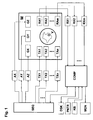
- Fig. 1 schematically shows an MR measuring system which is suited for performing the inventive method.
- the system contains a main magnet M for generating the basic magnetic field which is substantially homogeneous and static in a volume under investigation V.
- Three sets of gradient coils GX, GY, and GZ are introduced into the bore of the main magnet M, which surround the volume under investigation V, and can superpose additional magnetic fields of controllable duration and strength with constant gradients on the basic field.
- Gradient amplifiers AX, AY, and AZ which are driven by a sequence control unit SEQ for timely generation of gradient pulses, provide the gradient coils GX, GY, GZ with electric current for generating substantially linear gradient fields.
- transmitting elements TA1 to TAn are located in the gradient field system, the entirety of which is also called transmitting antenna means. They surround an object under investigation O and are fed by several independent RF power transmitters TX1...TXn. The RF pulses generated by these RF power transmitters TX1...TXn are determined by the sequence control unit SEQ and triggered at the correct time. The transmitting elements TA1 to TAn irradiate RF pulses onto the object under investigation O located in the volume under investigation V (as described in more detail in Fig. 8 ), thereby exciting the nuclear spins.
- the resulting magnetic resonance signals are converted into electric voltage signals using one or more RF receiver elements RA1, ..., RAm, which are then supplied to a corresponding number of receiver units RX1,...,RXm.
- the overall receiver elements RA1,..,RAm are also called receiver antenna means that consists of m receiver elements RA1, .., RAm. These are also located within the gradient coils GX, GY, GZ and surround the object under investigation O.
- the transmitting and receiver antenna means may also be designed and connected in such a fashion that one or more of the transmitting elements TA1 to TAn are also used for receiving the magnetic resonance signals. In this case, which is not considered in Fig.
- switching over between transmitting and receiving operation is effected by one or more electronic transmitting-receiver switch points that are controlled by the sequence control unit SEQ.
- this antenna(s) is/are connected to the corresponding RF power transmitter(s) and is/are separated from the allocated receiver channels, while for the receiver phases, the transmitters are separated and the receiver channel is connected.
- the received signals are amplified by the receiving units RX1 to RXm shown in Fig. 1 , and are converted into digital signals using conventional signal processing methods, and passed on to an electronic computer system COMP.
- the controlling computer system COMP serves to operate the entire MR measuring system and initiates performance of the pulse sequences through corresponding communication with the sequence control unit SEQ.
- the user-controlled or automatic execution of programs for adjusting the measuring system properties and/or for generating magnetic resonance images is also provided on this control computer system COMP, as well as the display of the reconstructed images, storage and management of measurement and image data and control programs.
- this computer system has at least one processor, one working memory, one computer keyboard KB, one display instrument PNTR, e.g. a computer mouse, one screen MON and one external digital storage unit DSK.
- the inventive method for determining the spatial distribution of magnetic resonance signals from a predetermined imaging area which consists of at least one predetermined extended and interrelated region within a volume under investigation of a magnetic resonance apparatus, is based on the principle to also impose spatial phase distribution onto the nuclear spins using a multi-dimensional RF pulse during excitation, in addition to spatial selection and amplitude modulation, and measure the resulting magnetic resonance signals.
- phase encoding step When the phases are imposed in several repetitive steps of this process, which comprises at least one excitation and at least one measuring period, called phase encoding step below, wherein in each step, the imposed phase distribution is varied in accordance with a predetermined phase encoding scheme for spatial encoding of the excited nuclear spins, the spatial distribution and/or spatial allocation of the magnetic resonance signals or values derived therefrom can be calculated from the measuring data in a reconstruction step.
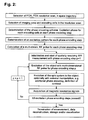
- Fig. 2 shows the inventive method steps which are described in more detail below:
- phase encoding scheme must be selected to obtain spatially accurate images and resolution, which are sufficient for the special case of application under the real conditions of the experiment.
- the encoding specification initially determines the allocations between the individual encoding cells and spatial codes. If each encoding cell is moreover allocated to a representative point in the imaging area, which, for spatially exact imaging should generally be located at least within the corresponding encoding cell, the encoding specification represents a mathematical image of the amount of spatial codes in the imaging area.
- the number of defined spatial codes corresponds to the number of encoding cells
- these spatial codes be recognized in the acquired magnetic resonance signals in the reconstruction step, and on this basis, the representative locations of the encoding cells are reconstructed for the corresponding signal components. Due to the discrete nature of the resolution grid, the phase distribution that is predetermined for each phase encoding step thereby corresponds to a discontinuous function of the location.
- phase distributions of the individual phase encoding steps can only be approximately realized due to physical principles and technical imperfections.
- the discontinuities in the phase distributions of the individual phase encoding steps are smoothed and the actually realized phase distribution thus corresponds to a continuous function of the location.
- a set of a finite number of discrete phase values, which is initially predetermined for each phase encoding step thus becomes a continuum of phase values.
- the encoding specification must consequently be defined such that all experimentally realized spatial codes are imaged in a suitable fashion in the volume under investigation.
- the spatial code of any point in the imaging area is observed to describe a criterion for the selection of a spatially accurately imaging encoding scheme.
- the spatial code at this point can be described as a linear combination of the spatial codes of the neighboring encoding cells. If it is then required that each convex linear combination of the spatial codes of spatially neighboring bordering encoding cells corresponds to a spatial code which is imaged by the encoding specification on a point which is located within the convex envelope of the encoding cells that contribute to this linear combination, one obtains a criterion for suitable spatial imaging exactness and resolution.
- This criterion prevents the generation of spatial codes in the transition regions of neighboring encoding cells, which correspond to points within the imaging area that are remote from these encoding cells, and that magnetic resonance signals from these regions superpose other image regions due to this wrong image allocation (so-called ghosts).
- two-dimensional Fourier encoding can be defined in correspondence with this criterion. It is basically possible to calculate a two-dimensional spatial distribution of the magnetic resonance signals using one-dimensional Fourier encoding for encoding a two-dimensional grid. Since this encoding violates the above-described criterion, the image quality will be inadequate due to the mentioned misallocations.
- the inventive method realizes partial, in particular also complete, spatial encoding of the magnetic resonance signals already during excitation of the nuclear spins to be measured, wherein imposition of spatial encoding of the nuclear spins to be measured is performed during excitation of the nuclear spins using multi-dimensional radio frequency pulses. This considerably reduces signal acquisition delays after excitation.
- this method permits spatially resolved measurement of nuclei with very short transverse relaxation times, e.g. 23 Na and 11 B, and tissue with very short transverse relaxation times, e.g. lung parenchyma and cartilage.
- the reduction of the acquisition delay also suppresses motion artefacts.
- the inventive method determines the two-dimensional distribution of magnetic resonance signals of a flat region of the material or tissue to be investigated, wherein, for spatial description within this area, the coordinate pairs are merely determined on the basis of the spatial encoding performed during excitation. When three-dimensional RF pulses are used, this distribution may also be determined for areas of any curvature based on the encoding during excitation.
- It also allows determination of a three-dimensional distribution of magnetic resonance signals within a spatially extended region of any shape of the material or tissue to be investigated. This is realized by using a two-dimensional RF pulse for encoding two spatial directions during excitation, and determining the third coordinate through frequency encoding during data read-out using a read gradient which is orthogonal to the gradients of the two-dimensional RF pulse.
- a three-dimensional RF pulse may alternatively also be used, which permits complete encoding for all three spatial directions already during excitation.
- phase encoding steps of both above-described method variants are performed with basically identical gradient pulses, and encoding is exclusively realized through variation of the amplitude and phase behavior with time of the RF pulses, such that many measuring errors that occur in classical spatial encoding and are caused by imperfections of the gradient generation, are intrinsically compensated for.
- phase ramps are e.g. used for encoding the individual resolution grid cells, wherein the phase values of the encoding cells for one phase encoding step substantially linearly increase in one predetermined spatial direction in each case, the dynamic region of the phase values required for encoding can be fully utilized for maximum extension of the imaging area in this direction, since the regions of the object under investigation, which are located outside of the imaging area, require no phase variation.
- phase variation need e.g. not correspond to the bases of a substantially spatially continuous function, as is the case in conventional Fourier encoding methods. If Fourier encoding is used in connection with the inventive method, the linearly increasing phase values to be realized for a phase encoding step may e.g. be allocated to the encoding cells in any order.
- a three-dimensional imaging area can be encoded with a three-, two- or one-dimensional scheme
- a two-dimensional imaging area can be encoded with a two- or one-dimensional scheme, and be accordingly reconstructed.
- An encoding scheme is preferred whose dimension corresponds to the distribution to be determined and which prevents small deviations in phase definition during excitation from causing great changes in the locations reconstructed from the actually realized phase values.
- the invention is particularly advantageous in that the imaging area can be very well adjusted to the region(s) which is/are of interest for spatially resolved investigation within the object under investigation, e.g. due to anatomical, morphological or functional conditions.
- the accuracy of this adjustment is primarily determined by the predetermined resolution grid, as long as the experimental conditions are set up in accordance with this grid.
- This adaptility also excludes certain regions of the object under investigation which could disturb the measurement, e.g. pulsating blood vessels in case of in-vivo investigations.
- the limitation of spatial encoding to the imaging area due to the associated reduced number of phase encoding steps may moreover be advantageous with respect to the measuring time to be used, in particular, when this imaging area is very small compared to the dimensions of the object under investigation and is to be investigated with high spatial resolution.
- the inventive method offers the possibility to efficiently perform magnetic resonance microscopy of inner structures of an extended object under investigation, and offers the additional advantage that tissue and materials can also be detected with extremely short relaxation times.
- Additional spatial encoding through classical phase encoding in a period subsequent to excitation and/or through classical frequency encoding during data acquisition can be advantageously used for different aims and applications. This depends i.a. on whether and to which extent this additional spatial encoding with respect to the encoded volume and/or with respect to the encoding direction is basically redundant or complementary with respect to the encoding performed during excitation, and how the later time of this encoding enters the measured spatial information. For example, by using this additional spatial encoding, the spatial resolution of the magnetic resonance signals of substantially resting nuclear spins can be improved, when the two encodings complement each other. Imaging errors may also be corrected when both encodings provide basically identical spatial information.
- spatial encoding performed during excitation and the later classical spatial encoding are e.g. advantageously performed in different volumes of the object under investigation, thereby gaining information about the motion of nuclear spins from the excitation volume to the classically encoded detection volume within the delay time.
- the inventive method may also be advantageously used in volume-selective spectroscopy: By dividing the region to be investigated into several encoding cells as the imaging area, one separate spectrum can be reconstructed for each encoding cell. When the magnetic basic field within the imaging area is inhomogeneous, the spectra of the individual encoding cells are displaced relative to each other. This instrumental imperfection can be corrected by moving the individual spectra on top of each other, e.g. by using a spectral reference line or due to known magnetic field charts, and the overall spectrum obtained through superposition from the individual spectra corrected in this fashion has a better spectral resolution than a spectrum obtained from the region to be investigated without inventive spatial encoding.
- FIG. 5 A preferred embodiment is explained below with respect to Figs. 5 - 13 . It concerns acquisition of a two-dimensional image of the magnetic resonance signals of a thin layer of an object under investigation. Two-dimensional spatial encoding within this layer is realized through excitation with two-dimensional RF pulses, and slice selection is realized using refocusing pulses under the action of a gradient which is orthogonal to this slice.
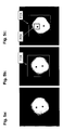
- a pilot image of a section through the object under investigation is initially acquired with conventional magnetic resonance acquisition technology.
- the pilot image of Fig. 5a is a cylindrical liquid phantom with two immersed plastic rods.
- an excitation region FOX field of excitation
- the excitation region FOX is comprehensively superposed by an orthogonal resolution grid with 64x64 square resolution grid cells (not shown). This resolution grid corresponds to the discrete image points of the excitation pattern of the transverse magnetization, i.e. it determines the spatial resolution for realizing this excitation pattern.
- the imaging area FOV is then defined within the excitation area FOX, which is to be imaged by the experiment ( Fig. 5c ).
- the imaging area FOV is a partial area of the excitation area FOX and corresponds to 16x16 fields of the resolution grid in this embodiment.
- the experiment is moreover planned by using a k-space trajectory that is adjusted to the problem.
- a two-dimensional RF pulse is to be used in this case, and consequently a spiral k-space trajectory would be suitable, which is schematically shown in Fig. 6 and is to be passed through from the outside to the inside in the experiment through corresponding switching of gradient pulses.
- the following definition step determines the phase encoding scheme for spatial encoding during excitation.
- Four neighboring fields of the resolution grid cells of the resolution grid, which are located within the imaging area FOV, are combined in each case into an encoding cell in the present example, to produce a two-dimensional grid of 8x8 encoding cells (shown in Fig. 7 ), which exactly covers the selected imaging area FOV.
- a two-dimensional phase encoding scheme with 64 phase encoding steps is determined for this two-dimensional matrix of 64 encoding cells, which permits later image reconstruction using two-dimensional Fourier transformation.
- a complex excitation pattern must be defined for each phase encoding step, i.e. the amplitude and phase of each of the 64x64 resolution grid cells must be predetermined.
- All resolution grid cells outside of the imaging area FOV are given an amplitude value of 0 for all phase encoding steps, whereas all resolution grid cells located in the imaging area FOV are given the same amplitude which is identical for all phase encoding steps and is calculated from the desired flip angle.
- the experiment is prepared by calculating the gradient and RF pulses to be applied.
- the gradient pulses are determined in accordance with conventional methods, as is described e.g. in paragraph 17.6 in [1].
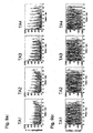
- Fig. 8 shows an object under investigation O, which is surrounded by a transmitting antenna means with four transmitting elements TA1, TA2, TA3, TA4, and a gradient system G.
- a complex RF pulse wave shape is calculated from the corresponding excitation pattern for each of the four transmitting channels.
- the method of Yip [10] or Grissom [11] may thereby be applied.
- the amplitude and phase behaviors of the four RF pulse wave shapes to be simultaneously applied are calculated by solving a matrix equation which connects the excitation pulses and the excitation pattern via a transition matrix, which depends i.a. on the determined transmission profiles of the transmission elements TA1, TA2, TA3, TA4 and the selected k-space trajectory.
- Fig. 9a shows the amplitude dependence
- Fig. 9b shows the phase dependence of RF pulse wave shapes, calculated in this fashion, of the four transmitting elements TA1, TA2, TA3, TA4 for one phase encoding step.
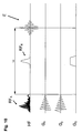
- each phase encoding step contains the sequence of gradient pulses G x , Gy and RF pulse HF A , which is schematically shown in Fig. 10 .
- slice-selective refocusing is performed after a time delay TE/2 using a 180° RF pulse HF R under the effect of a slice selection gradient G s which is applied orthogonally relative to the gradient pulses G x , Gy of the two-dimensional RF pulse.
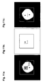
- FIG. 11a shows again the imaging area FOV, which is predetermined by the pilot image, and the grid of the encoding cells.
- Fig. 11b shows the result of reconstruction, i.e. the image of the imaging area FOV measured by excitation phase encoding, and Fig. 11c shows embedding of this image in the pilot image.
- Fig. 11b shows the substantial result of this embodiment.
- Figs. 11a and 11c are only auxiliary views for illustrating the meaning of this result.
Landscapes
- Physics & Mathematics (AREA)
- General Physics & Mathematics (AREA)
- High Energy & Nuclear Physics (AREA)
- Condensed Matter Physics & Semiconductors (AREA)
- Optics & Photonics (AREA)
- Spectroscopy & Molecular Physics (AREA)
- Nuclear Medicine, Radiotherapy & Molecular Imaging (AREA)
- Radiology & Medical Imaging (AREA)
- Engineering & Computer Science (AREA)
- Signal Processing (AREA)
- General Health & Medical Sciences (AREA)
- Health & Medical Sciences (AREA)
- Magnetic Resonance Imaging Apparatus (AREA)
Claims (15)
- Verfahren zur Bestimmung der räumlichen Verteilung von Magnetresonanzsignalen aus einem vorgegebenen Abbildungsgebiet, welches aus mindestens einer ausgedehnten Region innerhalb eines Untersuchungsvolumens einer Kernresonanzapparatur besteht, wobei transversale Magnetisierung von Kernspins durch mehrdimensionale HF-Pulse mittels Magnetfeldgradienten und einer HF-Sendeantenneneinrichtung mit mindestens einem Sendeelement angeregt wird, wobei- in einem Definitionsschritt
eine durch das Schalten von Magnetfeldgradienten zu erzeugende und bei der Anregung zu durchlaufende k-Raum-Trajektorie sowie ein Phasenkodierschema mit Phasenkodierschritten zur Orfskodierung festgelegt werden,- in einem Vorbereitungsschritt
für die gewählte k-Raum-Trajektorie für jedes Sendeelement der Sendeantenneneinrichtung der zeitliche Amplituden- und Phasenverlauf der zur Anregung der transversalen Magnetisierung der Kernspins einzustrahlenden HF-Pulse berechnet wird,- in einem Ausführungsschritt
während jedes Phasenkodierschritts transversale Magnetisierung der Kernspins innerhalb des Untersuchungsvolumens durch einen mehrdimensionalen HF-Puls angeregt wird, eine Phasenkodierung nach dem Phasenkodierschema stattfindet und Magnetresonanzsignale mittels einer Empfangsantenneneinrichtung aufgenommen werden,- in einem Rekonstruktionsschritt
aus den in allen Phasenkodierschritten aufgenommenen Magnetresonanzsignalen eine zwei- oder dreidimensionale räumliche Verteilung und/oder eine räumliche Zuordnung der Magnetresonanzsignale und/oder daraus abgeleiteter Größen berechnet wird, und- in einem Darstellungs-/Speicherungsschritt
die Ergebnisse der Rekonstruktion und/oder eine oder mehrere daraus abgeleitete Größen gespeichert und/oder dargestellt werden,
dadurch kennzeichnet,- dass im Definitionsschritt
ein das Untersuchungsobjekt abdeckendes zwei- oder dreidimensionales Auflösungsraster mit Auflösungsraster-Zellen vorgegeben wird,
für jede Region des Abbildungsgebietes ein mindestens zweidimensionales Gitter unmittelbar benachbarter Kodierzellen festgelegt wird, wobei jede Kodierzelle aus einer oder mehreren Auflösungsraster-Zellen des Abbildungsgebiets besteht, für welche dieselbe Ortskodierung erfolgen soll,
und für jeden Phasenkodierschritt ein komplexes Anregungsmuster durch Vorgabe der Amplituden und Phasen der in allen Auflösungsraster-Zellen anzuregenden transversalen Magnetisierung definiert wird, in dem die den Auflösungsraster-Zellen innerhalb des Abbildungsgebietes zugeordneten Amplituden einer vorgegebenen Verteilung entsprechend für jeden Phasenkodierschritt identisch, die den restlichen Auflösungsraster-Zellen zugeordneten Amplituden auf Null und die den Auflösungsraster-Zellen innerhalb des Abbildungsgebietes zugeordneten Phasen dem festgelegten Phasenkodierschema gemäß gesetzt werden,- dass im Vorbereitungsschritt
für jedes definierte komplexe Anregungsmuster der Phasenkodierschritte und für jedes Sendeelement die Berechnung des Amplituden- und Phasenverlaufs der einzustrahlenden HF-Pulse erfolgt,- dass im Ausführungsschritt
transversale Magnetisierung der Kernspins wiederholt angeregt wird, wobei für jeden Phasenkodierschritt der oder die für das oder die Sendelemente berechneten HF-Pulse während des Durchlaufens der vorgegebenen k-Raum-Trajektorie appliziert werden, so dass innerhalb des Abbildungsgebiets die Phasenkodierung während der Anregung der transversalen Magnetisierung der Kernspins erfolgt. - Verfahren nach Anspruch 1, dadurch gekennzeichnet, dass die Anregung der transversalen Magnetisierung der Kernspins mittels einer Sendeantenneneinrichtung mit mindestens zwei Sendeelementen erfolgt.
- Verfahren nach Anspruch 2, dadurch gekennzeichnet, dass ein Undersampling der k-Raum-Trajektorie erfolgt.
- Verfahren nach einem der vorangehenden Ansprüche, dadurch gekennzeichnet, dass jeder Phasenkodierschritt mit identischen Gradientenpulsen vorgenommen wird.
- Verfahren nach einem der vorangehenden Ansprüche, dadurch gekennzeichnet, dass die verwendete k-Raum-Trajektorie mindestens einen spiralförmigen Teil umfasst, der von außen nach innen oder von innen nach außen durchlaufen wird.
- Verfahren nach einem der vorangehenden Ansprüche, dadurch gekennzeichnet, dass das Abbildungsgebiet an anatomische, morphologische oder funktionelle Gegebenheiten des Untersuchungsobjekts angepasst wird.
- Verfahren nach einem der vorangehenden Ansprüche, dadurch gekennzeichnet, dass ein zweidimensionaler HF-Puls zur Anregung verwendet wird und eine räumliche Selektion in der dritten Raumrichtung durch eine schichtselektive Phasenrefokussierung erfolgt.
- Verfahren nach einem der Ansprüche 1 bis 6, dadurch gekennzeichnet, dass ein zweidimensionaler HF-Puls zur Anregung verwendet wird und eine Ortskodierung und/oder eine räumliche Selektion in der dritten Raumrichtung über Frequenzkodierung durch Einwirkung eines Gradienten in der zur Anregungskodierung orthogonalen Richtung während der Datenaufnahme erfolgt.
- Verfahren nach einem der Ansprüche 1 bis 6, dadurch gekennzeichnet, dass in jedem Phasenkodierschritt ein FID oder Spinecho aufgenommen wird und die räumliche Verteilung und/oder räumliche Zuordnung eines oder einer Kombination mehrerer, entsprechender Datenpunkte des FID bzw. Spinechos bestimmt wird.
- Verfahren nach einem der Ansprüche 1 bis 6, dadurch gekennzeichnet, dass in jedem Phasenkodierschritt ein FID oder Spinecho aufgenommen wird, aus welchem die spektrale Verteilung berechnet wird, und die räumliche Verteilung und/oder die räumliche Zuordnung einer Komponenten oder einer Kombination mehrerer Komponenten der spektralen Verteilung oder daraus abgeleiteter Größen bestimmt wird.
- Verfahren nach einem der vorangehenden Ansprüche, dadurch gekennzeichnet, dass das Phasenkodierschema derart festlegt wird, dass verschiedene, nicht unmittelbar räumlich benachbarte Auflösungsraster-Zellen innerhalb des Abbildungsgebietes dieselbe Ortskodierung erhalten.
- Verfahren nach einem der vorangehenden Ansprüche, dadurch gekennzeichnet, dass ortsabhängig jeweils unterschiedlich viele benachbarte Auflösungsraster-Zellen innerhalb des Abbildungsgebietes dieselbe Ortskodierung erhalten und damit das Phasenkodierschema derart festlegt wird, dass eine räumlich variierende Ortsauflösung erzielt wird, die den Gegebenheiten des Untersuchungsobjekts angepasst werden kann.
- Verfahren nach einem der vorangehenden Ansprüche, dadurch gekennzeichnet, dass die Anregungsamplituden innerhalb der Abbildungsregion einer Gleichverteilung entsprechend vorgegeben werden.
- Verfahren nach einem der vorangehenden Ansprüche, dadurch gekennzeichnet, dass eine der Anregung nachgelagerte separate Ortskodierung mittels Einwirkung von Gradienten zur Gewinnung zusätzlicher Ortsinformationen der Magnetresonanzsignale benutzt wird.
- Verfahren nach einem der vorangehenden Ansprüche, dadurch gekennzeichnet, dass die Zuordnungen der Magnetresonanzsignale zu den Kodierzellen, die aus der Phasenkodierung bei der Anregung der Kernspins gewonnenen wurden, dazu verwendet werden, ortsabhängige Korrekturen der aufgenommen Signale und/oder rekonstruierten und/oder daraus abgeleiteten Daten vorzunehmen, insbesondere Korrekturen von Fehlern, die durch räumliche Inhomogenitäten des Grundmagnetfeldes hervorgerufen werden.
Applications Claiming Priority (2)
| Application Number | Priority Date | Filing Date | Title |
|---|---|---|---|
| DE102007044463A DE102007044463B4 (de) | 2007-09-18 | 2007-09-18 | Verfahren zur Bestimmung der räumlichen Verteilung von Magnetresonanzsignalen durch mehrdimensionale HF-Anregungspulse |
| PCT/EP2008/007617 WO2009036936A1 (en) | 2007-09-18 | 2008-09-13 | Magnetic resonance using multi-dimensional rf excitation pulses |
Publications (2)
| Publication Number | Publication Date |
|---|---|
| EP2193385A1 EP2193385A1 (de) | 2010-06-09 |
| EP2193385B1 true EP2193385B1 (de) | 2011-03-02 |
Family
ID=40130855
Family Applications (1)
| Application Number | Title | Priority Date | Filing Date |
|---|---|---|---|
| EP08802167A Not-in-force EP2193385B1 (de) | 2007-09-18 | 2008-09-13 | Magnetresonanz unter verwendung von mehrdimensionalen rf-erregungsimpulsen |
Country Status (5)
| Country | Link |
|---|---|
| US (1) | US8082127B2 (de) |
| EP (1) | EP2193385B1 (de) |
| AT (1) | ATE500518T1 (de) |
| DE (2) | DE102007044463B4 (de) |
| WO (1) | WO2009036936A1 (de) |
Families Citing this family (26)
| Publication number | Priority date | Publication date | Assignee | Title |
|---|---|---|---|---|
| DE102006058162B3 (de) * | 2006-12-09 | 2008-06-12 | Bruker Biospin Mri Gmbh | Verfahren zur Gewinnung von Amplituden- und Phasenverläufen von HF-Pulsen für die räumlich-selektive Anregung |
| US8154289B2 (en) * | 2008-04-11 | 2012-04-10 | The General Hospital Corporation | Method for joint sparsity-enforced k-space trajectory and radiofrequency pulse design |
| JP5449805B2 (ja) * | 2008-04-25 | 2014-03-19 | 株式会社東芝 | 磁気共鳴イメージング装置 |
| DE102008021736B3 (de) * | 2008-04-30 | 2009-12-10 | Bruker Biospin Mri Gmbh | Verfahren zur Bestimmung der räumlichen Verteilung von Magnetresonanzsignalen beim Einsatz von lokalen ortskodierenden Magnetfeldern |
| US8032335B2 (en) * | 2008-05-02 | 2011-10-04 | Emory University | Evaluating magnetic resonance spectra |
| WO2010047245A1 (ja) * | 2008-10-20 | 2010-04-29 | 株式会社 日立メディコ | 磁気共鳴イメージング装置及び方法 |
| DE102008061455B4 (de) | 2008-12-10 | 2011-03-17 | Siemens Aktiengesellschaft | Verfahren und Vorrichtung zur Bestimmung einer vorbestimmten Signalamplitude bei MR-Messungen |
| DE102009002112B3 (de) | 2009-04-01 | 2010-08-19 | Bruker Biospin Mri Gmbh | Verfahren zur Gewinnung von Amplituden- und Phasenverläufen von HF-Pulsen für die räumlich-selektive Anregung |
| US8305077B2 (en) * | 2009-07-06 | 2012-11-06 | University Of Utah Research Foundation | Phase sensitive radio frequency mapping for magnetic resonance imaging |
| DE102009045464B4 (de) | 2009-10-07 | 2011-09-15 | Bruker Biospin Mri Gmbh | Verfahren zur ortsabhängigen Änderung der Magnetisierung in einem Objekt im Rahmen eines Experimentes der magnetischen Resonanz |
| DE102010038775B4 (de) * | 2010-08-02 | 2012-10-31 | Siemens Aktiengesellschaft | Dynamische Phasenkorrektur bei einem Mehrkanal-HF-Sendemodul |
| DE102011007825B4 (de) * | 2011-04-20 | 2012-11-22 | Bruker Biospin Mri Gmbh | Verfahren zur Bestimmung der räumlichen Verteilung von Magnetresonanzsignalen in Subvolumen eines Untersuchungsobjektes |
| US8866478B2 (en) | 2011-07-13 | 2014-10-21 | Siemens Aktiengesellschaft | Method and processor and magnetic resonance apparatus for designing RF pulses to mitigate off-resonance effects |
| US9086446B2 (en) * | 2011-11-29 | 2015-07-21 | General Electric Company | Method and system for B1 field mapping in magnetic resonance imaging |
| WO2013172980A1 (en) * | 2012-05-16 | 2013-11-21 | Wollin Ventures, Inc. | Apparatus and method for mapping and measurement of spatially and temporally distributed induced small phase deviations in magnetic resonance utilizing deconvolution |
| US11131734B2 (en) * | 2012-12-13 | 2021-09-28 | Gagan Sidhu | Processing multidimensional signals |
| CN105120745B (zh) * | 2013-05-17 | 2017-12-19 | 株式会社日立制作所 | 磁共振成像装置以及磁共振成像方法 |
| US20150134261A1 (en) * | 2013-11-14 | 2015-05-14 | J. Michael O'Connor | Synchronization of patient motion detection equipment with medical imaging systems |
| US9995808B2 (en) * | 2014-03-10 | 2018-06-12 | Vanderbilt University | MRI using RF gradients for spatial encoding |
| US11047935B2 (en) | 2015-05-14 | 2021-06-29 | Ohio State Innovation Foundation | Systems and methods for estimating complex B1+ fields of transmit coils of a magnetic resonance imaging (MRI) system |
| WO2018136705A1 (en) | 2017-01-19 | 2018-07-26 | Ohio State Innovation Foundation | Estimating absolute phase of radio frequency fields of transmit and receive coils in a magnetic resonance |
| CN108696468B (zh) * | 2018-04-25 | 2020-10-02 | 哈尔滨工业大学 | 一种基于欠采样的二相编码信号的参数估计方法 |
| EP3709043B1 (de) * | 2019-03-11 | 2023-08-23 | Siemens Healthcare GmbH | Verfahren und vorrichtung zur steuerung eines magnetresonanzbildgebungssystems |
| CN111624673B (zh) * | 2020-04-24 | 2023-12-05 | 博微太赫兹信息科技有限公司 | 一种采用压缩感知码分复用的人体安检系统 |
| US20240069134A1 (en) * | 2021-02-24 | 2024-02-29 | Case Western Reserve University | System and method for b1-selective excitation for spatial localization in magnetic resonance imaging |
| DE102021203270A1 (de) * | 2021-03-31 | 2022-10-06 | Siemens Healthcare Gmbh | Verfahren zur verbesserten simultanen Aufnahme von Messdaten aus zumindest zwei Schichten eines Untersuchungsobjekts mittels Magnetresonanz |
Family Cites Families (13)
| Publication number | Priority date | Publication date | Assignee | Title |
|---|---|---|---|---|
| US4689566A (en) * | 1985-07-17 | 1987-08-25 | Advanced Nmr Systems, Inc. | NMR phase encoding using phase varying rf pulses |
| GB8819705D0 (en) * | 1988-08-19 | 1988-09-21 | Royal Marsden Hospital | Improvements in nmr spectroscopy localisation |
| US5270653A (en) | 1992-04-10 | 1993-12-14 | The Board Of Trustees Of The Leland Stanford Junior University | Selective three dimensional excitation for magnetic resonance applications |
| DE19543079A1 (de) | 1995-11-18 | 1997-05-22 | Philips Patentverwaltung | Verfahren zum Bestimmen der räumlichen und/oder spektralen Verteilung der Kernmagnetisierung |
| US5903149A (en) | 1997-04-11 | 1999-05-11 | The Trustees Of The University Of Pennsylvania | Three-dimensional localized proton NMR spectroscopy using a hybrid of one-dimensional hadamard with two-dimensional chemical shift imaging |
| US6873153B2 (en) * | 2003-07-07 | 2005-03-29 | Yeda Research And Development Co., Ltd. | Method and apparatus for acquiring multidimensional spectra and improved unidimensional spectra within a single scan |
| US7251520B2 (en) * | 2003-07-08 | 2007-07-31 | General Electric Company | Method and apparatus of slice selective magnetization preparation for moving table MRI |
| DE102004011874B4 (de) * | 2004-03-11 | 2006-04-20 | Universitätsklinikum Freiburg | Verfahren zur Messung der Magnetresonanz (NMR) mittels Continuously Refocused Multiecho Spectroscopic Imaging |
| US20060132132A1 (en) * | 2004-12-21 | 2006-06-22 | General Electric Company | Method and system for MR scan acceleration using selective excitation and parallel transmission |
| DE102005051021A1 (de) * | 2005-10-25 | 2007-04-26 | Universitätsklinikum Freiburg | Apparaturen und Verfahren zur kernspintomographischen Aufnahme mit lokalen Magnetfeldgradienten in Verbindung mit lokalen Empfangsspulen |
| US7719269B2 (en) * | 2006-11-21 | 2010-05-18 | General Electric Company | System and method for fast MR imaging of metabolites at selective excitation frequencies |
| DE102007054744B4 (de) * | 2007-11-16 | 2009-09-10 | Universitätsklinikum Freiburg | NMR-Tomographieverfahren auf Basis von NBSEM mit 2D-Ortskodierung durch zwei gegeneinander verdrehte Multipol-Gradientenfelder |
| US7772844B2 (en) * | 2008-01-30 | 2010-08-10 | General Electric Company | System and method for tissue specific MR imaging of metabolites using spectral-spatially formed stimulated echo |
-
2007
- 2007-09-18 DE DE102007044463A patent/DE102007044463B4/de not_active Expired - Fee Related
-
2008
- 2008-09-13 DE DE602008005329T patent/DE602008005329D1/de active Active
- 2008-09-13 EP EP08802167A patent/EP2193385B1/de not_active Not-in-force
- 2008-09-13 US US12/678,292 patent/US8082127B2/en not_active Expired - Fee Related
- 2008-09-13 WO PCT/EP2008/007617 patent/WO2009036936A1/en not_active Ceased
- 2008-09-13 AT AT08802167T patent/ATE500518T1/de not_active IP Right Cessation
Also Published As
| Publication number | Publication date |
|---|---|
| US8082127B2 (en) | 2011-12-20 |
| DE102007044463B4 (de) | 2009-05-14 |
| US20100286500A1 (en) | 2010-11-11 |
| EP2193385A1 (de) | 2010-06-09 |
| ATE500518T1 (de) | 2011-03-15 |
| DE602008005329D1 (de) | 2011-04-14 |
| WO2009036936A1 (en) | 2009-03-26 |
| DE102007044463A1 (de) | 2009-04-02 |
Similar Documents
| Publication | Publication Date | Title |
|---|---|---|
| US8082127B2 (en) | Method for determining the spatial distribution of magnetic resonance signals through multi-dimensional RF excitation pulses | |
| US7843195B2 (en) | Method for determining the spatial distribution of magnetic resonance signals with use of local spatially encoding magnetic fields | |
| US7999545B2 (en) | Method for obtaining amplitude and phase profiles of RF pulses for spatially selective excitation | |
| US10557903B2 (en) | Slice multiplexing method and apparatus for magnetic resonance imaging | |
| JP6166232B2 (ja) | 磁気共鳴制御シーケンスの決定 | |
| JP6270709B2 (ja) | 磁気共鳴生データの再構成方法および装置 | |
| US9689945B2 (en) | Virtual coil emulation in parallel transmission MRI | |
| US9977108B2 (en) | Metal resistant MR imaging reference scan | |
| EP2615470A1 (de) | MR-Bildgebung mit B1-Kartierung | |
| EP2496954B1 (de) | MR-Bildgebung mithilfe von Navigatoren | |
| EP4071494A1 (de) | Verfahren zur erfassung eines dreidimensionalen magnetresonanzbilddatensatzes und zur erzeugung eines bewegungskorrigierten bilddatensatzes | |
| US8076939B2 (en) | Method for fast magnetic resonance radiofrequency coil transmission profile mapping | |
| US20140070805A1 (en) | Mr imaging with b1 mapping | |
| US20090121714A1 (en) | Method and magnetic resonance system for determining the flip angle distribution in a volume of an examination subject | |
| US7109711B2 (en) | MRI method and apparatus with elimination of the ambiguity artifact | |
| EP3044604B1 (de) | Metallbeständige mr-bildgebung | |
| EP2902794A1 (de) | MR-Bildgebung mithilfe von mehrkanaliger HF-Anregung | |
| EP4246170A1 (de) | Verfahren zur erfassung eines magnetresonanzbilddatensatzes und zur erzeugung eines bewegungskorrigierten bilddatensatzes | |
| CN104101849A (zh) | 磁共振系统控制序列的确定 | |
| EP3191862B1 (de) | Magnetresonanzbildgebung mit null-echozeit | |
| US7038453B2 (en) | Method and magnetic resonance tomography apparatus for spatially resolved measurement of the B1 field distribution | |
| CN102866371A (zh) | 磁场不敏感的化学交换饱和转移成像 | |
| US6323646B1 (en) | Method and apparatus for producing diffusion weighted MR images | |
| US6239599B1 (en) | Method and apparatus for identifying errors in magnetic resonance imaging examinations | |
| US20050240095A1 (en) | Variable flip angle, sar-reduced state free precession mri acquisition |
Legal Events
| Date | Code | Title | Description |
|---|---|---|---|
| PUAI | Public reference made under article 153(3) epc to a published international application that has entered the european phase |
Free format text: ORIGINAL CODE: 0009012 |
|
| 17P | Request for examination filed |
Effective date: 20100419 |
|
| AK | Designated contracting states |
Kind code of ref document: A1 Designated state(s): AT BE BG CH CY CZ DE DK EE ES FI FR GB GR HR HU IE IS IT LI LT LU LV MC MT NL NO PL PT RO SE SI SK TR |
|
| AX | Request for extension of the european patent |
Extension state: AL BA MK RS |
|
| GRAP | Despatch of communication of intention to grant a patent |
Free format text: ORIGINAL CODE: EPIDOSNIGR1 |
|
| DAX | Request for extension of the european patent (deleted) | ||
| GRAS | Grant fee paid |
Free format text: ORIGINAL CODE: EPIDOSNIGR3 |
|
| GRAA | (expected) grant |
Free format text: ORIGINAL CODE: 0009210 |
|
| AK | Designated contracting states |
Kind code of ref document: B1 Designated state(s): AT BE BG CH CY CZ DE DK EE ES FI FR GB GR HR HU IE IS IT LI LT LU LV MC MT NL NO PL PT RO SE SI SK TR |
|
| REG | Reference to a national code |
Ref country code: GB Ref legal event code: FG4D |
|
| REG | Reference to a national code |
Ref country code: CH Ref legal event code: EP |
|
| REG | Reference to a national code |
Ref country code: IE Ref legal event code: FG4D |
|
| REF | Corresponds to: |
Ref document number: 602008005329 Country of ref document: DE Date of ref document: 20110414 Kind code of ref document: P |
|
| REG | Reference to a national code |
Ref country code: DE Ref legal event code: R096 Ref document number: 602008005329 Country of ref document: DE Effective date: 20110414 |
|
| REG | Reference to a national code |
Ref country code: NL Ref legal event code: VDEP Effective date: 20110302 |
|
| PG25 | Lapsed in a contracting state [announced via postgrant information from national office to epo] |
Ref country code: SE Free format text: LAPSE BECAUSE OF FAILURE TO SUBMIT A TRANSLATION OF THE DESCRIPTION OR TO PAY THE FEE WITHIN THE PRESCRIBED TIME-LIMIT Effective date: 20110302 Ref country code: HR Free format text: LAPSE BECAUSE OF FAILURE TO SUBMIT A TRANSLATION OF THE DESCRIPTION OR TO PAY THE FEE WITHIN THE PRESCRIBED TIME-LIMIT Effective date: 20110302 Ref country code: LT Free format text: LAPSE BECAUSE OF FAILURE TO SUBMIT A TRANSLATION OF THE DESCRIPTION OR TO PAY THE FEE WITHIN THE PRESCRIBED TIME-LIMIT Effective date: 20110302 Ref country code: ES Free format text: LAPSE BECAUSE OF FAILURE TO SUBMIT A TRANSLATION OF THE DESCRIPTION OR TO PAY THE FEE WITHIN THE PRESCRIBED TIME-LIMIT Effective date: 20110613 Ref country code: NO Free format text: LAPSE BECAUSE OF FAILURE TO SUBMIT A TRANSLATION OF THE DESCRIPTION OR TO PAY THE FEE WITHIN THE PRESCRIBED TIME-LIMIT Effective date: 20110602 Ref country code: LV Free format text: LAPSE BECAUSE OF FAILURE TO SUBMIT A TRANSLATION OF THE DESCRIPTION OR TO PAY THE FEE WITHIN THE PRESCRIBED TIME-LIMIT Effective date: 20110302 Ref country code: GR Free format text: LAPSE BECAUSE OF FAILURE TO SUBMIT A TRANSLATION OF THE DESCRIPTION OR TO PAY THE FEE WITHIN THE PRESCRIBED TIME-LIMIT Effective date: 20110603 |
|
| LTIE | Lt: invalidation of european patent or patent extension |
Effective date: 20110302 |
|
| PG25 | Lapsed in a contracting state [announced via postgrant information from national office to epo] |
Ref country code: CY Free format text: LAPSE BECAUSE OF FAILURE TO SUBMIT A TRANSLATION OF THE DESCRIPTION OR TO PAY THE FEE WITHIN THE PRESCRIBED TIME-LIMIT Effective date: 20110302 Ref country code: AT Free format text: LAPSE BECAUSE OF FAILURE TO SUBMIT A TRANSLATION OF THE DESCRIPTION OR TO PAY THE FEE WITHIN THE PRESCRIBED TIME-LIMIT Effective date: 20110302 Ref country code: NL Free format text: LAPSE BECAUSE OF FAILURE TO SUBMIT A TRANSLATION OF THE DESCRIPTION OR TO PAY THE FEE WITHIN THE PRESCRIBED TIME-LIMIT Effective date: 20110302 Ref country code: FI Free format text: LAPSE BECAUSE OF FAILURE TO SUBMIT A TRANSLATION OF THE DESCRIPTION OR TO PAY THE FEE WITHIN THE PRESCRIBED TIME-LIMIT Effective date: 20110302 Ref country code: SI Free format text: LAPSE BECAUSE OF FAILURE TO SUBMIT A TRANSLATION OF THE DESCRIPTION OR TO PAY THE FEE WITHIN THE PRESCRIBED TIME-LIMIT Effective date: 20110302 Ref country code: BG Free format text: LAPSE BECAUSE OF FAILURE TO SUBMIT A TRANSLATION OF THE DESCRIPTION OR TO PAY THE FEE WITHIN THE PRESCRIBED TIME-LIMIT Effective date: 20110602 |
|
| PG25 | Lapsed in a contracting state [announced via postgrant information from national office to epo] |
Ref country code: BE Free format text: LAPSE BECAUSE OF FAILURE TO SUBMIT A TRANSLATION OF THE DESCRIPTION OR TO PAY THE FEE WITHIN THE PRESCRIBED TIME-LIMIT Effective date: 20110302 |
|
| PG25 | Lapsed in a contracting state [announced via postgrant information from national office to epo] |
Ref country code: EE Free format text: LAPSE BECAUSE OF FAILURE TO SUBMIT A TRANSLATION OF THE DESCRIPTION OR TO PAY THE FEE WITHIN THE PRESCRIBED TIME-LIMIT Effective date: 20110302 Ref country code: PT Free format text: LAPSE BECAUSE OF FAILURE TO SUBMIT A TRANSLATION OF THE DESCRIPTION OR TO PAY THE FEE WITHIN THE PRESCRIBED TIME-LIMIT Effective date: 20110704 |
|
| PG25 | Lapsed in a contracting state [announced via postgrant information from national office to epo] |
Ref country code: RO Free format text: LAPSE BECAUSE OF FAILURE TO SUBMIT A TRANSLATION OF THE DESCRIPTION OR TO PAY THE FEE WITHIN THE PRESCRIBED TIME-LIMIT Effective date: 20110302 Ref country code: CZ Free format text: LAPSE BECAUSE OF FAILURE TO SUBMIT A TRANSLATION OF THE DESCRIPTION OR TO PAY THE FEE WITHIN THE PRESCRIBED TIME-LIMIT Effective date: 20110302 Ref country code: IS Free format text: LAPSE BECAUSE OF FAILURE TO SUBMIT A TRANSLATION OF THE DESCRIPTION OR TO PAY THE FEE WITHIN THE PRESCRIBED TIME-LIMIT Effective date: 20110702 Ref country code: SK Free format text: LAPSE BECAUSE OF FAILURE TO SUBMIT A TRANSLATION OF THE DESCRIPTION OR TO PAY THE FEE WITHIN THE PRESCRIBED TIME-LIMIT Effective date: 20110302 |
|
| PLBE | No opposition filed within time limit |
Free format text: ORIGINAL CODE: 0009261 |
|
| STAA | Information on the status of an ep patent application or granted ep patent |
Free format text: STATUS: NO OPPOSITION FILED WITHIN TIME LIMIT |
|
| 26N | No opposition filed |
Effective date: 20111205 |
|
| PG25 | Lapsed in a contracting state [announced via postgrant information from national office to epo] |
Ref country code: PL Free format text: LAPSE BECAUSE OF FAILURE TO SUBMIT A TRANSLATION OF THE DESCRIPTION OR TO PAY THE FEE WITHIN THE PRESCRIBED TIME-LIMIT Effective date: 20110302 Ref country code: DK Free format text: LAPSE BECAUSE OF FAILURE TO SUBMIT A TRANSLATION OF THE DESCRIPTION OR TO PAY THE FEE WITHIN THE PRESCRIBED TIME-LIMIT Effective date: 20110302 |
|
| REG | Reference to a national code |
Ref country code: DE Ref legal event code: R097 Ref document number: 602008005329 Country of ref document: DE Effective date: 20111205 |
|
| PG25 | Lapsed in a contracting state [announced via postgrant information from national office to epo] |
Ref country code: MC Free format text: LAPSE BECAUSE OF NON-PAYMENT OF DUE FEES Effective date: 20110930 |
|
| PG25 | Lapsed in a contracting state [announced via postgrant information from national office to epo] |
Ref country code: IT Free format text: LAPSE BECAUSE OF FAILURE TO SUBMIT A TRANSLATION OF THE DESCRIPTION OR TO PAY THE FEE WITHIN THE PRESCRIBED TIME-LIMIT Effective date: 20110302 |
|
| REG | Reference to a national code |
Ref country code: IE Ref legal event code: MM4A |
|
| PG25 | Lapsed in a contracting state [announced via postgrant information from national office to epo] |
Ref country code: IE Free format text: LAPSE BECAUSE OF NON-PAYMENT OF DUE FEES Effective date: 20110913 |
|
| PG25 | Lapsed in a contracting state [announced via postgrant information from national office to epo] |
Ref country code: MT Free format text: LAPSE BECAUSE OF FAILURE TO SUBMIT A TRANSLATION OF THE DESCRIPTION OR TO PAY THE FEE WITHIN THE PRESCRIBED TIME-LIMIT Effective date: 20110302 |
|
| REG | Reference to a national code |
Ref country code: CH Ref legal event code: PL |
|
| PG25 | Lapsed in a contracting state [announced via postgrant information from national office to epo] |
Ref country code: LU Free format text: LAPSE BECAUSE OF NON-PAYMENT OF DUE FEES Effective date: 20110913 |
|
| PG25 | Lapsed in a contracting state [announced via postgrant information from national office to epo] |
Ref country code: LI Free format text: LAPSE BECAUSE OF NON-PAYMENT OF DUE FEES Effective date: 20120930 Ref country code: CH Free format text: LAPSE BECAUSE OF NON-PAYMENT OF DUE FEES Effective date: 20120930 |
|
| PG25 | Lapsed in a contracting state [announced via postgrant information from national office to epo] |
Ref country code: TR Free format text: LAPSE BECAUSE OF FAILURE TO SUBMIT A TRANSLATION OF THE DESCRIPTION OR TO PAY THE FEE WITHIN THE PRESCRIBED TIME-LIMIT Effective date: 20110302 |
|
| PG25 | Lapsed in a contracting state [announced via postgrant information from national office to epo] |
Ref country code: HU Free format text: LAPSE BECAUSE OF FAILURE TO SUBMIT A TRANSLATION OF THE DESCRIPTION OR TO PAY THE FEE WITHIN THE PRESCRIBED TIME-LIMIT Effective date: 20110302 |
|
| REG | Reference to a national code |
Ref country code: FR Ref legal event code: PLFP Year of fee payment: 9 |
|
| REG | Reference to a national code |
Ref country code: FR Ref legal event code: PLFP Year of fee payment: 10 |
|
| REG | Reference to a national code |
Ref country code: FR Ref legal event code: PLFP Year of fee payment: 11 |
|
| P01 | Opt-out of the competence of the unified patent court (upc) registered |
Effective date: 20231027 |
|
| REG | Reference to a national code |
Ref country code: GB Ref legal event code: 732E Free format text: REGISTERED BETWEEN 20240822 AND 20240828 |
|
| PGFP | Annual fee paid to national office [announced via postgrant information from national office to epo] |
Ref country code: DE Payment date: 20240919 Year of fee payment: 17 |
|
| PGFP | Annual fee paid to national office [announced via postgrant information from national office to epo] |
Ref country code: GB Payment date: 20240923 Year of fee payment: 17 |
|
| PGFP | Annual fee paid to national office [announced via postgrant information from national office to epo] |
Ref country code: FR Payment date: 20240924 Year of fee payment: 17 |
|
| REG | Reference to a national code |
Ref country code: DE Ref legal event code: R081 Ref document number: 602008005329 Country of ref document: DE Owner name: BRUKER BIOSPIN GMBH & CO. KG, DE Free format text: FORMER OWNER: BRUKER BIOSPIN MRI GMBH, 76275 ETTLINGEN, DE |
|
| REG | Reference to a national code |
Ref country code: DE Ref legal event code: R119 Ref document number: 602008005329 Country of ref document: DE |
|
| GBPC | Gb: european patent ceased through non-payment of renewal fee |
Effective date: 20250913 |
|
| PG25 | Lapsed in a contracting state [announced via postgrant information from national office to epo] |
Ref country code: GB Free format text: LAPSE BECAUSE OF NON-PAYMENT OF DUE FEES Effective date: 20250913 |
|
| PG25 | Lapsed in a contracting state [announced via postgrant information from national office to epo] |
Ref country code: DE Free format text: LAPSE BECAUSE OF NON-PAYMENT OF DUE FEES Effective date: 20260401 |
|
| PG25 | Lapsed in a contracting state [announced via postgrant information from national office to epo] |
Ref country code: FR Free format text: LAPSE BECAUSE OF NON-PAYMENT OF DUE FEES Effective date: 20250930 |