EP2193388B1 - Distanzmessinstrument und verfahren - Google Patents
Distanzmessinstrument und verfahren Download PDFInfo
- Publication number
- EP2193388B1 EP2193388B1 EP07818567.5A EP07818567A EP2193388B1 EP 2193388 B1 EP2193388 B1 EP 2193388B1 EP 07818567 A EP07818567 A EP 07818567A EP 2193388 B1 EP2193388 B1 EP 2193388B1
- Authority
- EP
- European Patent Office
- Prior art keywords
- signal
- light
- input
- output
- variable gain
- Prior art date
- Legal status (The legal status is an assumption and is not a legal conclusion. Google has not performed a legal analysis and makes no representation as to the accuracy of the status listed.)
- Active
Links
Images


Classifications
-
- G—PHYSICS
- G01—MEASURING; TESTING
- G01C—MEASURING DISTANCES, LEVELS OR BEARINGS; SURVEYING; NAVIGATION; GYROSCOPIC INSTRUMENTS; PHOTOGRAMMETRY OR VIDEOGRAMMETRY
- G01C3/00—Measuring distances in line of sight; Optical rangefinders
- G01C3/02—Details
- G01C3/06—Use of electric means to obtain final indication
- G01C3/08—Use of electric radiation detectors
-
- H—ELECTRICITY
- H03—ELECTRONIC CIRCUITRY
- H03G—CONTROL OF AMPLIFICATION
- H03G3/00—Gain control in amplifiers or frequency changers
- H03G3/20—Automatic control
- H03G3/30—Automatic control in amplifiers having semiconductor devices
- H03G3/3084—Automatic control in amplifiers having semiconductor devices in receivers or transmitters for electromagnetic waves other than radiowaves, e.g. lightwaves
-
- G—PHYSICS
- G01—MEASURING; TESTING
- G01S—RADIO DIRECTION-FINDING; RADIO NAVIGATION; DETERMINING DISTANCE OR VELOCITY BY USE OF RADIO WAVES; LOCATING OR PRESENCE-DETECTING BY USE OF THE REFLECTION OR RERADIATION OF RADIO WAVES; ANALOGOUS ARRANGEMENTS USING OTHER WAVES
- G01S17/00—Systems using the reflection or reradiation of electromagnetic waves other than radio waves, e.g. lidar systems
- G01S17/02—Systems using the reflection of electromagnetic waves other than radio waves
- G01S17/06—Systems determining position data of a target
- G01S17/08—Systems determining position data of a target for measuring distance only
- G01S17/10—Systems determining position data of a target for measuring distance only using transmission of interrupted, pulse-modulated waves
-
- G—PHYSICS
- G01—MEASURING; TESTING
- G01S—RADIO DIRECTION-FINDING; RADIO NAVIGATION; DETERMINING DISTANCE OR VELOCITY BY USE OF RADIO WAVES; LOCATING OR PRESENCE-DETECTING BY USE OF THE REFLECTION OR RERADIATION OF RADIO WAVES; ANALOGOUS ARRANGEMENTS USING OTHER WAVES
- G01S7/00—Details of systems according to groups G01S13/00, G01S15/00, G01S17/00
- G01S7/48—Details of systems according to groups G01S13/00, G01S15/00, G01S17/00 of systems according to group G01S17/00
- G01S7/481—Constructional features, e.g. arrangements of optical elements
- G01S7/4814—Constructional features, e.g. arrangements of optical elements of transmitters alone
-
- G—PHYSICS
- G01—MEASURING; TESTING
- G01S—RADIO DIRECTION-FINDING; RADIO NAVIGATION; DETERMINING DISTANCE OR VELOCITY BY USE OF RADIO WAVES; LOCATING OR PRESENCE-DETECTING BY USE OF THE REFLECTION OR RERADIATION OF RADIO WAVES; ANALOGOUS ARRANGEMENTS USING OTHER WAVES
- G01S7/00—Details of systems according to groups G01S13/00, G01S15/00, G01S17/00
- G01S7/48—Details of systems according to groups G01S13/00, G01S15/00, G01S17/00 of systems according to group G01S17/00
- G01S7/481—Constructional features, e.g. arrangements of optical elements
- G01S7/4818—Constructional features, e.g. arrangements of optical elements using optical fibres
-
- G—PHYSICS
- G01—MEASURING; TESTING
- G01S—RADIO DIRECTION-FINDING; RADIO NAVIGATION; DETERMINING DISTANCE OR VELOCITY BY USE OF RADIO WAVES; LOCATING OR PRESENCE-DETECTING BY USE OF THE REFLECTION OR RERADIATION OF RADIO WAVES; ANALOGOUS ARRANGEMENTS USING OTHER WAVES
- G01S7/00—Details of systems according to groups G01S13/00, G01S15/00, G01S17/00
- G01S7/48—Details of systems according to groups G01S13/00, G01S15/00, G01S17/00 of systems according to group G01S17/00
- G01S7/483—Details of pulse systems
- G01S7/486—Receivers
- G01S7/4868—Controlling received signal intensity or exposure of sensor
-
- G—PHYSICS
- G01—MEASURING; TESTING
- G01S—RADIO DIRECTION-FINDING; RADIO NAVIGATION; DETERMINING DISTANCE OR VELOCITY BY USE OF RADIO WAVES; LOCATING OR PRESENCE-DETECTING BY USE OF THE REFLECTION OR RERADIATION OF RADIO WAVES; ANALOGOUS ARRANGEMENTS USING OTHER WAVES
- G01S7/00—Details of systems according to groups G01S13/00, G01S15/00, G01S17/00
- G01S7/48—Details of systems according to groups G01S13/00, G01S15/00, G01S17/00 of systems according to group G01S17/00
- G01S7/497—Means for monitoring or calibrating
Definitions
- the present invention relates to a distance measuring instrument and a distance measuring method.
- the invention relates to a distance measuring instrument and method where modulated measuring light is emitted towards an object and wherein measuring light received back from the object is detected and analyzed. A value representing a distance from the object is determined based on such analysis.
- a conventional distance measuring instrument comprises a laser generating pulses of measuring light, and optics to direct the pulses of measuring light towards an object. Pulses of measuring light received back from the object are supplied to a light sensor to generate electrical signals corresponding to the light pulses, and the electrical pulse signals are amplified and analyzed. The analysis includes determination of occurrence times between subsequent pulses to determine the distance from the object based on the determined occurrence times.
- US 2005/0094238 A1 discloses a distance measuring instrument comprising a light source, a light detector, optics configured to direct measuring light emitted from the light source towards an object and to direct measuring light received back from the object to the detector, a first signal analyser, a second signal analyser, and a variable gain amplifier, wherein an output of the light sensor is connected to an input of the variable gain amplifier, and output of the variable gain amplifier is connected to a signal input of the first signal analyzer, an output of the first signal analyzer is connected to a gain setting input of the variable gain amplifier, an output of the variable gain amplifier is connected to an input of the second signal analyzer, and wherein the second signal analyzer is configured to determine occurrence times of a predetermined signal feature of signals supplied to its input relative to emission times of pulses of measuring light directed to the object.
- the distance measuring instrument comprises a variable gain amplifier for amplifying a detected signal, wherein a higher gain is applied when the detected signal has a low intensity and wherein a relatively lower gain -is applied when the detected signal has a relatively higher intensity.
- the distance measuring instrument comprises a first analyzer for analyzing the detected signal such that the gain of the variable gain amplifier can be set based on a result of this analysis.
- the distance measuring instrument comprises a signal delay module for delaying a first portion of a detected signal, wherein a first analysis of a second portion of the detected signal is performed while the first portion is delayed.
- a signal delay module for delaying a first portion of a detected signal, wherein a first analysis of a second portion of the detected signal is performed while the first portion is delayed.
- the gain value is determined such that the amplified signal outputted from the variable gain amplifier has a substantially constant intensity which is relatively independent of the intensity of the detected signal.
- the amplified signal can then be subject to further analysis, wherein this analysis is relatively independent of the intensity of the original detected signal. This can be of a particular advantage in practice since measuring light received back from the object and the corresponding detected signals may vary by many orders of magnitude, depending on the distance of the object from the measuring instrument and on an albedo of the object.
- a distance measuring instrument comprises at least one light source; at least one light detector; optics to direct measuring light emitted from the at least one light source towards an object and to direct measuring light received back from the object to the at least one detector; a signal delay module; a first signal analyzer; and a variable gain amplifier; wherein: an output of the at least one light sensor is connected to an input of the signal delay module; the output of the at least one light sensor is connected to a signal input of the first signal analyzer; an output of the signal delay module is connected to a signal input of the variable gain amplifier; and an output of the first signal analyzer is connected to a gain setting input of the variable gain amplifier.
- connection is not limited to mean directly connected but shall also encompass functional connections with intermediate components.
- an output of a first component is connected to an input of a second component this comprises a direct connection wherein an electrical conductor directly supplies an outputted signal from the first component substantially unchanged to the input of the second component, and this also comprise that the connection is via one or more additional components, such as an intermediate amplifier or filter which modifies the signal outputted from the first component before it is inputted to the second component.
- additional components such as an intermediate amplifier or filter which modifies the signal outputted from the first component before it is inputted to the second component.
- the connection is a functional connection in that, if the signal outputted from the first component undergoes gradual or prompt changes, a corresponding and maybe modified change will be applied to the input of the second component.
- the signal delay module delays an inputted signal by a predetermined signal delay time before it is outputted.
- the signal delay time can be greater than or equal to one of a processing time associated with the first signal analyzer, a settling time associated with the variable gain amplifier, and a sum of the processing time of the first signal analyzer and the settling time of the variable gain amplifier.
- the processing time associated with the first signal analyzer is defined in the context of the present invention as the time elapsed from the application of an ideal instantaneous step signal to the input of the first signal analyzer to a time at which the output of the first signal analyzer has entered and remained within a value range between 0.5 to 1.5 times the final value established at the output of the first signal analyzer.
- the settling time associated with the variable gain amplifier is defined in the context of the present invention as the time elapsed from supplying the settled output from the first signal analyzer to the variable gain amplifier and a time when the variable gain amplifier has adjusted its amplification to its final value with an accuracy within 0.5 to 1.5 times the final value of the adjusted amplification.
- the signal delay time is greater than one of 0.5 ns, 1.0 ns, 3 ns, 5 ns and 7 ns.
- the first signal analyzer is configured to provide an output signal at its output which is indicative of an intensity of an input signal supplied to its signal input.
- the output signal can be indicative of a peak value of the input signal, wherein a maximum amplitude of the input signal may represent the peak value.
- other values such as an integrated energy and other suitable values, can be determined by the first signal analyzer to be indicative of the intensity or other characteristics of the input signal.
- variable gain amplifier is an analog amplifier.
- variable gain amplifier comprises a divider circuit.
- variable gain amplifier is a digital amplifier. According to exemplary embodiments herein, the variable gain amplifier comprises plural fixed gain amplifiers.
- the at least one light source of the distance measuring instrument comprises a signal laser and a light amplifier including at least one fiber doped with a rare earth element such as erbium and ytterbium.
- a rare earth element such as erbium and ytterbium.
- the doped fiber laser has advantages over Q-switched microchip lasers used as light sources in conventional distance measuring instruments.
- the Q-switched microchip laser does not allow a precise definition of emission times of light pulses, whereas the doped fiber laser allows for an accurate timing of emitted light pulses.
- the monitoring portion 10 of the emitted light 9 is directed to the detector to allow the analyzing and control system 21 to monitor the emitted measuring light.
- the analyzing and control system 21 may determine occurrence times of particular features of that portion 10 which are relevant for the distance measurement.
- a start time of a distance measurement can be determined based on the detection and analysis of the monitoring portion 10 of the light 9 emitted from the light source 5.
- a larger portion 17 of the light 9 emitted from the source 5 traverses the partially reflective surface 13 and is reflected from a mirror surface 15, and surface 13 and is reflected from a mirror surface 15, and further reflected from a mirror 18 such that the measuring light reflected from mirror 18 is directed along an optical axis 22 of a lens 23.
- a portion of the light pulse directed to the object is branched off by reflective surfaces 13 and 14 to be incident on detector 9 which is the same detector which also receives the light pulse reflected back from the object.
- detector 9 which is the same detector which also receives the light pulse reflected back from the object.
- both the start time and the stop time of the distance measurement are derived from light pulses incident on the same detector 9.
- the start time of the distance measurement is determined by other principles.
- the instrument may comprise an additional light detector, such as a PIN diode to receive a portion of the light pulse emitted towards the object. The start time of the distance measurement can then be generated based on output signals of such additional detector.
- the start time of the distance measurement directly from an occurrence time of a trigger signal for emitting light pulses from the light source.
- a trigger signal for emitting light pulses from the light source it is possible to calibrate the instrument relative to an object disposed at a known distance from the instrument, for example.
- the analyzing and control system 21 comprises an analyzer 31 for analyzing shapes or characteristics of the electrical signals provided at the output 29 of detector 9.
- intensities of the signals outputted from the detector 9 may vary by plural orders of magnitude depending on a distance of the object 3 from the instrument 1 and on an albedo of the object 3.
- the signals provided by the detector 9 have a very high dynamic range, accordingly, whereas the analyzer 31 has a limited dynamic range determined by a configuration of the analyzer 31. Therefore, the analyzer and control system 21 comprises a variable gain amplifier 33 configured to amplify signals provided by the detector 9 with a suitable gain such that the amplified signal has intensities within a reduced dynamic range suitable for analysis by analyzer 31.
- An output 35 of the variable gain amplifier 33 is connected to a first signal input 36 of analyzer 31.
- the delay module is designed such that it has a delay time of 5 ns or 6 ns or more.
- a configuration of the signal analyzer 41 and the variable gain amplifier 33 is shown in more detail in Figure 2 .
- the signal analyzer 41 comprises a high speed peak detector and hold module 67 having a signal input S providing the signal input 45 of the signal analyzer 41, a reset input R providing the reset input 55 of the signal analyzer 41, and an output O which is connected to a first signal input S 1 of an analog MAX module 69 which outputs the maximum of the two signals supplied to its inputs S 1 and S 2 .
- the input S 2 is used to supply a signal S f to the signal analyzer 41, wherein the signal S f represents a maximum gain to be applied to the variable gain amplifier 33.
- a fixed gain corresponding to a level Vg can be supplied to input S 2 of the MUX module 71 to set the gain of the variable gain amplifier 33 to a value represented by level V g .
- the gain of the x/y divider 61 is then set to 1/V g , which is independent on the intensity of the signal S supplied to the input 45 of the signal analyzer 41. This mode effectively disables the signal analyzer 41 and can be used when the adaptive amplification of the inputted signals S depending on their intensities is not desired.
- the memory 83 is accessible from a controller 91 which can be any suitable computing device or network of devices such as personal computers or other hardware.
- the controller 91 can be connected to user interface devices, such as a display 92 and a keyboard 93, or other suitable user interfaces such as touch screens, for example.
- user interface devices such as a display 92 and a keyboard 93, or other suitable user interfaces such as touch screens, for example.
- the controller 91 accessing the memory 83 can perform an analysis of the recorded digital values. For example, the controller may determine features of the digitized signal, such as occurrences of signal values exceeding a threshold or a center of gravity of a digitized pulse signal.
- the controller 91 may also calculate a time when the determined signal feature occurred. Further, if there are two subsequent digitized pulses stored in the memory, the controller can determine the centers of gravity of both signals in terms of memory addresses and then calculate a temporal distance between the occurrence of two pulses based on a rate of the clock 81 advancing the address generator 85.
- the distance measuring instrument as shown in Figure 1 further comprises an actuator 95 driven by the controller 91 for changing an orientation of the optical axis 22 of optics 7.
- the optics 7, light source 5 and detector 9 can be arranged as a module which is rotatable relative to a stand placed on the ground about a horizontal axis and a vertical axis.
- the controller 91 can then drive the actuator 95 such that the object 3 is scanned with measuring light wherein the distance of subsequent scan points of the object 3 from the measuring instrument 1 is determined as illustrated above.
- the resulting data also refer to as a point cloud, can be stored by the controller 91 for further analysis in a memory, such as a hard disc 97 shown in Figure 1 .
- FIG 4 is a schematic illustration of a portion of an analyzer and control system 21a of a distance measuring instrument 1a which can be of a similar structure as that illustrated with reference to Figure 1 above.
- a signal analyzer 41a shown in Figure 4 provides the combined functions of a high speed peak detector and hold module and MAX module as represented by a functional box 41' shown in broken lines in Figure 2 .
- the signal analyzer 41a comprises a gain 1 buffer, for example an operational amplifier 101 having a non-inverted input which is supplied with the input signal S via an ideal diode 103, and an inverted input which is supplied with a feedback from its output.
- a hold capacitor 105 is connected to the non-inverting input of the operational amplifier 101 and is charged with a voltage S f representing the maximum gain upon operation of a reset switch 107.
- FIG. 5 shows an exemplary embodiment of a variable gain amplifier 33b of an analyzer and control system 21b of a distance measuring instrument 1b which can be similar in structure to that shown in Figure 1 .
- the variable gain amplifier 33b comprises an xy multiplier 111 having a X input which is supplied with the signal S to be amplified via a constant gain amplifier 63b, wherein it is also possible to omit the amplifier 63b and directly supply the signal S to be amplified to the X input of the xy multiplier.
- An operational amplifier 113 receives the signal S 0 representing the reciprocal gain at its inverting input via a resistor, and a non-inverting input of operational amplifier 113 is connected to ground.
- An output of the operational amplifier 113 provides the output O of the variable gain amplifier 33b at an output 35b, wherein the output of the operational amplifier 131 is also connected to the Y input of the xy multiplier 111.
- An output of the xy multiplier is supplied as a feedback via a resistor R to the inverting input of operational amplifier 113.
- FIG. 6 is a schematic illustration of a further embodiment of a variable gain amplifier 33c which may have an improved bandwidth, in particular for low levels of input signal S, as compared to the embodiment shown in Figure 5 .
- the variable gain amplifier 33c comprises an xy multiplier 121 having an X input supplied with the signal S to be amplified via a fixed gain amplifier 63c, and an Y input connected to an output of a xy divider 123.
- the xy divider has an X input supplied with a constant signal (represented as "1" in Figure 6 ), and an Y input supplied with the reciprocal gain S 0 .
- FIG. 7 shows a further embodiment of a variable gain amplifier 33d which could be used in the distance measuring instrument shown in Figure 1 .
- the variable gain amplifier 33d comprises an xy multiplier 127 having an X input supplied with the signal S to be amplified, and an output which is connected to an X input of a further xy multiplier 129.
- An output of the xy multiplier 129 provides the output of the variable gain amplifier 33d.
- the reciprocal gain S 0 is supplied to the input of a square rooter 131, and an output of the square rooter 131 is connected to an Y input of a xy divider 133.
- a constant signal (represented by "1" in Figure 7 ) is supplied to an X input of xy divider 133.
- An output of the xy divider 133 is connected to Y inputs of both xy multipliers 127 and 129.
- FIG. 8 illustrates a portion of a further embodiment of an analyzer and control system 21e which could be used in a distance measuring instrument according to an embodiment of the invention.
- a signal analyzer 41e and a variable gain amplifier 33e are implemented using digital electronics.
- the signal analyzer 41e comprises an analog digital converter 141 supplied with the signal S generated by a light detector.
- the signal is digitized by the analog digital converter 141 and supplied as a digital signal to a maximum encoder 143 which provides a maximum value of the received digital values at an output 42e of the signal analyzer 41e.
- the variable gain amplifier 33e comprises a digital variable gain amplifier 151 having a signal input which is supplied with the signal to be amplified from a delay module 51e.
- the digital representation of the peak signal provided at the output 42e of the signal analyzer 41e can be directly supplied to a digital gain input of digital variable gain amplifier 151.
- a look-up table 153 is provided to receive the representation of the peak value and to translate this peak value to a gain which is supplied to the digital gain input of the digital variable gain amplifier 151.
- the look-up table is prepared in advance to take possible non-linear effects of the digital variable gain amplifier 151 into account or to achieve a desired further variation of the gain to be applied for amplification of the signal S based on the peak value detected by signal analyzer 41e.
- FIG. 9 is a schematic illustration of a portion of an analyzer and control system 21f according to a still further embodiment of the present invention.
- a signal analyzer 41f of system 21f comprises an array of plural high speed comparators and latches 161. For example, a number of the comparators and latches may be six. Each of the comparators and latches is supplied with the signal S to be analyzed, and the signal analyzer 41f further comprises an array of plural maximum encoders 163, wherein each maximum encoder is connected to a corresponding latch of the array of comparators and latches 161. The outputs of the plural maximum encoders 163 form a digital representation of the analyzed signal S.
- These outputs of the maximum encoder 163 also drive a corresponding number of high speed turn on/off switched amplifiers 33f such that an output 35f thereof provides the delayed and amplified signal S wherein the gain applied for amplification is dependent on a peak level of the signal S.
- the signal analyzer 31 is generally configured to determine occurrence times of signal features of the signal S generated by the light source 9.
- Figure 10 is a schematic illustration of possible temporal pulse shapes of signal S.
- Figure 10a shows a pulse 171 of a relatively small peak value
- Figure 10b shows a pulse 172 of a relatively higher peak value.
- An occurrence time of the signal speaks is indicated by t p . Since it is not easily possible to determine the occurrence times t p of the peak values, the signal analyzer 31 can be configured to determine occurrence times t f of features different from the occurrence times t p of the peak values. For example, the occurrence times t f can be defined as those times when the signal exceeds a predetermined constant threshold Lc.
- FIG 11 illustrates an embodiment of a signal analyzer 31g which could be used in the distance measuring instrument illustrated in Figure 1 .
- the signal analyzer 31g comprises a very fast comparator 181 having a first input receiving the signal to be analyzed from a delay module (not shown in Figure 11 ), and having a second input connected to an output of a multiplier 183.
- Multiplier 183 has an input connected to a second signal input 185 of the signal analyzer 31g and which is connected to an output of signal analyzer 41 and representing the gain to be applied by the variable gain amplifier 33.
- the multiplier is configured to multiply the signal supplied to its input by a fixed factor, such as 0.5 in the illustrated example.
- An output S d of the comparator 181 may then provide a step-shaped signal which changes value when the signal supplied at input 36g exceeds the signal supplied at input 85 and multiplied by the fixed factor.
- the occurrence time of change of value of the signal S d can then be used as the feature time t f of the analyzed signal, and such feature time t f is a better representation of the occurrence time tp of the peak value of the signal at varying signal intensities as compared to using a constant threshold as illustrated in Figure 10 above.
- the signal analyzer shown in Figure 3 further comprises an analog digital converter 187 to translate the analog value provided by signal analyzer 41 and which represents the gain applied to the variable gain amplifier into a digital value.
- This digital value is accessible by the controller 91 and can be taken into account when the occurrence times of the signals are determined by the controller 91.
- Figure 12 illustrates a further embodiment of a signal analyzer 31h which has a configuration similar to that shown in Figure 11 in that multipliers 183a are connected to inputs of vary fast comparators 181a.
- the other inputs of the vary fast comparators 181a are all supplied with the amplified signal to be analyzed.
- an array of multipliers 183a and comparators 181h is provided, wherein the multipliers 183a are configured to multiply their input signals with different fixed vectors x 1 ,..., xi, ..., x n .
- Outputs S d1 ,..., S di ,..., S dn represent occurrence times of different features of the analyzed signals, wherein the different occurrence times are those times where the signal exceeds different signal levels determined by the multiplication factors xi of the multipliers 183h. This allows to analyze the occurrence times at different levels of the signal, wherein the signal noise will be different at different signal levels. The possibility of analyzing the signal at different levels may then improve the total accuracy.
- Figure 13 illustrates a further embodiment of components of an analyzing and control system 21k which can be used in embodiments of the distance measuring instrument.
- the analyzing and control system 21k comprises a signal analyzer 41k for determining the gain to be used for amplifying a signal S as supplied to both the signal analyzer 41k and a delay module 51k.
- the arrangement of components shown in Figure 13 is similar to that shown in Figure 2 , wherein a variable gain amplifier 33k is embodied as a multiplier 111k.
- baluns 251 are connected to an output 42k of the signal analyzer 41k and an output 53k of the delay module 51k, respectively, for supplying the respective signals to the multiplier 111k via two symmetric lines.
- a level shifter 253 is provided in the symmetric line between the output 42k of the signal analyzer 41k and an input of the multiplier 111k.
- a further balun 251 is connected to the symmetric line output of the multiplier 111k such that an output 35k of the amplified signal is again on an asymmetric line.
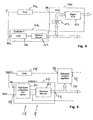
- FIG 15 shows a possible embodiment of a light source 5i which can be used in the distance measuring instrument shown in Figure 1 .
- the light source 5i comprises a signal laser 201 driven by a controller 91i to generate light pulses at a repetition rate determined by controller 91i and which may range, for example, from 1 kHz to 1000 kHz.
- the signal laser 201 may have an output power in a range from 1 to 20 mW, for example. It is, however, also possible to use light sources of a substantially higher output power having peak powers of about 5 W, for example.
- the signal laser may include a temperature stabilization or not.
- the laser light generated by the signal laser is amplified by a two-stage amplifier 203 having a first stage 205 and a second stage 207, wherein each stage comprises a single mode rare earth doped fiber 209 and a wavelength division multiplexer 211.
- the rare earth element used for doping the fiber is erbium in the present example.
- Both the light to be amplified and the pump light are supplied to the doped fibers 205 via the wavelength division multiplexers 211.
- the pump light is generated by a pump laser 213 and supplied to the wavelength division multiplexers 211 of stages 205 and 207 via a beam splitter 215.
- an optical filter 217 is provided between the two stages 205 and 207.
- the filter 217 may include an optical isolator, a wavelength filter and a time gating device, such as an acousto optic modulator, an electro optic modulator and a saturable absorber.
- the filter 217 is a narrowband wavelength filter and an optical isolator.
- the light is amplified in a single mode rare earth doped fiber, wherein the pump light is supplied into the fiber via a wavelength division multiplexer. It is also possible to use double clad fibers having a single mode rare earth doped core included in a clad to which the pump light is supplied. The pump light then enters the core on the clad.
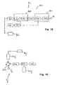
- FIG 16 schematically illustrates a further embodiment of a light source 5j which can be used in the instrument illustrated in Figure 1 .
- the light source 5j in Figure 16 comprises a signal laser 201j generating output light which is supplied to a port 1 of a circulator 221. This light is outputted from a port 2 of the circulator 221 to be supplied to a rare earth doped fiber 209j.
- An amplified signal emitted from the fiber 209j traverses a wavelength division multiplexer 221j and is reflected from a combined filter and mirror 223 such that it again traverses the wavelength division multiplexer 221j to be further amplified in a doped fiber 209j.
- the further amplified light enters the circulator 221 at its port 2 and exits the circulator 221 at its port 3 to form measuring light 9j which can be emitted towards an object.
- the doped fiber 209 is pumped with light from a pump laser 213j which is coupled into the fiber via the wavelength division multiplexer 221j.
Landscapes
- Engineering & Computer Science (AREA)
- Physics & Mathematics (AREA)
- General Physics & Mathematics (AREA)
- Radar, Positioning & Navigation (AREA)
- Remote Sensing (AREA)
- Computer Networks & Wireless Communication (AREA)
- Electromagnetism (AREA)
- Optical Radar Systems And Details Thereof (AREA)
Claims (14)
- Entfernungsmessgerät, das Folgendes umfasst:mindestens eine Lichtquelle (5);mindestens einen Lichtdetektor (9);eine Optik (7), die dafür konfiguriert ist, Messlicht, das von der mindestens einen Lichtquelle (5) ausgesendet wird, auf ein Objekt (3) zu richten und Messlicht, das von dem Objekt zurückkommend empfangen wird, auf den mindestens einen Lichtdetektor (9) zu richten;einen ersten Signalanalysator (41);einen zweiten Signalanalysator (31);einen Verstärker mit variabler Verstärkung (33);wobei:ein Ausgang (29) des mindestens einen Lichtdetektors (9) mit einem Signaleingang (45) des ersten Signalanalysators (41) verbunden ist;ein Ausgang (42) des ersten Signalanalysators (41) mit einem Verstärkungseinstelleingang (43) des Verstärkers mit variabler Verstärkung (33) verbunden ist;ein Ausgang (35) des Verstärkers mit variabler Verstärkung (33) mit einem ersten Eingang (36) des zweiten Signalanalysators (31) verbunden ist;wobei der zweite Signalanalysator (31) dafür konfiguriert ist, Zeitpunkte des Auftretens eines zuvor festgelegten Signalmerkmals von Signalen, die seinem ersten Eingang (36) zugeführt werden, relativ zu Abstrahlungszeiten von auf das Objekt (3) gerichteten Pulsen von Messlicht zu bestimmen;gekennzeichnet durchein Signalverzögerungsmodul (51);wobei:der Ausgang (29) des mindestens einen Lichtdetektors (9) des Weiteren mit einem Eingang (52) des Signalverzögerungsmoduls (51) verbunden ist;ein Ausgang (53) des Signalverzögerungsmoduls (51) mit einem Signaleingang (37) des Verstärkers mit variabler Verstärkung (33) verbunden ist.
- Entfernungsmessgerät gemäß Anspruch 1, wobei der erste Signalanalysator (41) mindestens eines der folgenden Merkmale aufweist:- er ist dafür konfiguriert, an seinem Ausgang ein Ausgangssignal bereitzustellen, das einen Spitzenwert eines Eingangssignals anzeigt, das in seinen Signaleingang eingespeist wird;- er umfasst einen Amplitudendetektor (67); und- er umfasst einen Rücksetzungseingang (55).
- Entfernungsmessgerät gemäß Anspruch 1 oder 2, wobei der Verstärker mit variabler Verstärkung (33) einen Teilerschaltkreis (61; 123, 133) umfasst, wobei der Verstärker mit variabler Verstärkung des Weiteren einen ersten Multiplikatorschaltkreis (121, 125) umfasst, wobei ein Ausgang des Teilerschaltkreises mit einem ersten Eingang des ersten Multiplikatorschaltkreises verbunden ist,
wobei der Verstärker mit variabler Verstärkung (33) des Weiteren einen zweiten Multiplikator (127) umfasst, wobei ein erster Eingang des zweiten Multiplikators mit dem Ausgang (53) des Signalverzögerungsmoduls verbunden ist, wobei ein Ausgang des zweiten Multiplikators (127) mit einem zweiten Eingang des ersten Multiplikators (125) verbunden ist,
wobei der Verstärker mit variabler Verstärkung des Weiteren einen Quadratwurzelbildner (131) umfasst, wobei ein Eingang des Quadratwurzelbildners (131) mit einem Ausgang (52) des ersten Signalanalysators (51) verbunden ist und ein Ausgang des Quadratwurzelbildners (131) mit einem ersten Eingang des Teilerschaltkreises (133) verbunden ist. - Entfernungsmessgerät gemäß einem der Ansprüche 1 bis 3, wobei der Verstärker mit variabler Verstärkung einen digitalen Verstärker mit variabler Verstärkung (151) und einen Maximumcodierer (143) und eine Nachschlagetabelle (153) umfasst, wobei ein Ausgang des Maximumcodierers (143) mit einem Eingang der Nachschlagetabelle (153) verbunden ist und ein Ausgang der Nachschlagetabelle mit einem Verstärkungseinstelleingang des digitalen Verstärkers mit variabler Verstärkung (151) verbunden ist.
- Entfernungsmessgerät gemäß einem der Ansprüche 1 bis 4, wobei der zweite Signalanalysator (31) mindestens eines der folgenden Merkmale aufweist:- er ist dafür konfiguriert, den Zeitpunkt des Auftretens als einen Zeitpunkt zu bestimmen, in dem das Signal, das in den ersten Eingang des zweiten Signalanalysators eingespeist wird, einen zuvor festgelegten Pegel überschreitet; und- er umfasst einen ersten Analog-Digital-Wandler (75), der dafür konfiguriert ist, eine Reihe von digitalen Werten zu generieren, die aufeinanderfolgende Lesewerte eines Signals darstellen, das in den ersten Signaleingang (36) des zweiten Signalanalysators eingespeist wurde;- er ist dafür konfiguriert, die generierte Reihe von digitalen Werten auf der Basis eines Ausgangssignals des ersten Signalanalysators (41) zu verarbeiten.
- Entfernungsmessgerät gemäß einem der Ansprüche 1 bis 5, das des Weiteren einen Auslöserschaltkreis (91) umfasst, der einen Ausgang hat, der mit der mindestens einen Lichtquelle (5) verbunden ist, wobei der Auslöserschaltkreis und die mindestens eine Lichtquelle dafür konfiguriert sind, die mindestens eine Lichtquelle so zu betreiben, dass sie aufeinanderfolgende Messlicht-Pulse aussendet.
- Entfernungsmessgerät gemäß Anspruch 6, wobei die Optik (7) dafür konfiguriert ist, einen Teil des Messlichts, das von der mindestens einen Lichtquelle (5) ausgesendet wird, direkt auf den mindestens einen Detektor (9) zu richten, ohne diesen Teil auf das Objekt (3) zu richten.
- Entfernungsmessgerät gemäß einem der Ansprüche 1 bis 7, wobei die mindestens eine Lichtquelle (5) Folgendes umfasst:mindestens eine Lichtleitfaser (209), die mit einem Seltenerd-Element dotiert ist,einen Pumplaser (213), der mit der mindestens einen Lichtleitfaser (209) verbunden ist, undeinen Signallaser (201), der mit der mindestens einen Lichtleitfaser (209) verbunden ist,wobei die mindestens eine Lichtleitfaser (209) dafür konfiguriert ist, Licht, das von dem Signallaser (201) als das Messlicht empfangen wurde, zu verstärken und auszusenden.
- Entfernungsmessgerät gemäß Anspruch 8, wobei das Seltenerd-Element mindestens eines von Ytterbium und Erbium umfasst, und/oder wobei die mindestens eine Lichtleitfaser eine zweifach ummantelte Faser ist, die einen Monomoden-Faserkern aufweist.
- Entfernungsmessverfahren, das Folgendes umfasst:Aussenden eines Messlicht-Pulses in Richtung eines Objekts;Empfangen eines Messlicht-Pulses von dem Objekt und Erzeugen eines Pulssignals, das dem Messlicht-Puls entspricht, der von dem Objekt kommend empfangen wurde;Verzögern eines ersten Abschnitts des generierten Pulssignals über einen zuvor festgelegten Zeitraum;Erzeugen eines Intensitätssignals, das eine Intensität des generierten Pulssignals anzeigt, während der erste Abschnitt des generierten Pulssignals verzögert wird;Verstärken des verzögerten ersten Abschnitts des generierten Pulssignals unter Verwendung einer Verstärkung, die von dem generierten Intensitätssignal abhängig ist;Bestimmen eines Wertes, der eine Entfernung darstellt, auf der Basis eines Zeitpunktes des Auftretens eines Signalmerkmals des verstärkten verzögerten ersten Abschnitts des generierten Pulssignals relativ zu einer Zeit, die von einer Aussendezeit des in Richtung des Objekts ausgesendeten Messlicht-Pulses abhängig ist.
- Entfernungsmessverfahren gemäß Anspruch 10, wobei das Erzeugen des Intensitätssignals das Bestimmen eines Maximalwertes des generierten Pulssignals enthält.
- Entfernungsmessverfahren gemäß Anspruch 10 oder 11, wobei das Verstärken des verzögerten ersten Abschnitts des generierten Pulssignals das Teilen eines dem verzögerten ersten Abschnitt entsprechenden Signals durch das Intensitätssignal umfasst.
- Entfernungsmessverfahren gemäß einem der Ansprüche 10 bis 12, das des Weiteren das Erzeugen eines Lichtpulses umfasst, wobei ein erster Abschnitt des generierten Lichtpulses den in Richtung des Objekts ausgesendeten Messlicht-Puls bildet; und
Empfangen eines zweiten Abschnitts des generierten Lichtpulses, ohne ihn auf das Objekt zu richten, und Erzeugen eines Pulssignals entsprechend dem empfangenen zweiten Abschnitt von Licht, das nicht auf das Objekt gerichtet wird. - Entfernungsmessverfahren gemäß Anspruch 13, wobei ein erstes Pulssignal generiert wird, das dem empfangenen zweiten Abschnitt von Licht entspricht, das nicht auf das Objekt gerichtet wird;
wobei ein zweites Pulssignal generiert wird, das dem Messlicht-Puls entspricht, der von dem Objekt kommend empfangen wird; und
wobei der Wert, der die Entfernung darstellt, anhand einer zeitlichen Distanz zwischen den ersten und zweiten Pulssignalen bestimmt wird.
Applications Claiming Priority (1)
| Application Number | Priority Date | Filing Date | Title |
|---|---|---|---|
| PCT/EP2007/008487 WO2009039875A1 (en) | 2007-09-28 | 2007-09-28 | Distance measuring instrument and method |
Publications (2)
| Publication Number | Publication Date |
|---|---|
| EP2193388A1 EP2193388A1 (de) | 2010-06-09 |
| EP2193388B1 true EP2193388B1 (de) | 2016-03-09 |
Family
ID=39434328
Family Applications (1)
| Application Number | Title | Priority Date | Filing Date |
|---|---|---|---|
| EP07818567.5A Active EP2193388B1 (de) | 2007-09-28 | 2007-09-28 | Distanzmessinstrument und verfahren |
Country Status (4)
| Country | Link |
|---|---|
| US (3) | US8149391B2 (de) |
| EP (1) | EP2193388B1 (de) |
| CN (1) | CN101828128B (de) |
| WO (1) | WO2009039875A1 (de) |
Families Citing this family (28)
| Publication number | Priority date | Publication date | Assignee | Title |
|---|---|---|---|---|
| CN101828128B (zh) | 2007-09-28 | 2013-06-05 | 天宝3D扫描公司 | 距离测量仪器和方法 |
| EP2182379B1 (de) * | 2008-10-30 | 2012-09-19 | Sick Ag | Entfernungsmessender Laserscanner |
| US9091754B2 (en) | 2009-09-02 | 2015-07-28 | Trimble A.B. | Distance measurement methods and apparatus |
| US8922923B2 (en) | 2011-03-01 | 2014-12-30 | Seagate Technology Llc | Interleaved automatic gain control for asymmetric data signals |
| TWI476364B (zh) | 2011-05-09 | 2015-03-11 | Lin Cho Yi | 感測方法與裝置 |
| US9572682B2 (en) | 2011-09-29 | 2017-02-21 | Arthromeda, Inc. | System and method for precise prosthesis positioning in hip arthroplasty |
| EP2597483B8 (de) * | 2011-11-25 | 2017-06-07 | Safran Vectronix AG | Entfernungsmesser |
| US9157989B2 (en) | 2012-08-29 | 2015-10-13 | Trimble Ab | Distance measurement methods and apparatus |
| US9597096B2 (en) | 2013-03-15 | 2017-03-21 | Arthromeda, Inc. | Systems and methods for providing alignment in total knee arthroplasty |
| EP2846173B1 (de) | 2013-09-09 | 2019-06-19 | Trimble AB | Mehrdeutigkeitsausgleich in der Flugzeitmessung |
| JP6299500B2 (ja) * | 2014-01-29 | 2018-03-28 | 株式会社東京精密 | 多点距離測定装置及び方法並びに形状測定装置 |
| CN106461780B (zh) * | 2014-05-28 | 2019-06-18 | 特林布尔有限公司 | 补偿的距离测量的方法和装置 |
| JP6269334B2 (ja) * | 2014-06-12 | 2018-01-31 | 株式会社東京精密 | 多点距離測定装置及び形状測定装置 |
| US9812486B2 (en) * | 2014-12-22 | 2017-11-07 | Google Inc. | Time-of-flight image sensor and light source driver having simulated distance capability |
| CN104777470A (zh) * | 2015-03-20 | 2015-07-15 | 中国科学院合肥物质科学研究院 | 一种扩展脉冲激光近程动态增益范围电路 |
| CN106160706A (zh) * | 2015-04-24 | 2016-11-23 | 南京理工大学 | 一种双通道时刻鉴别电路 |
| WO2017210418A1 (en) * | 2016-06-01 | 2017-12-07 | Velodyne Lidar, Inc. | Multiple pixel scanning lidar |
| EP3330741B1 (de) * | 2016-12-05 | 2019-02-13 | Sick Ag | Optoelektronischer sensor und verfahren zur erfassung von objekten in einem erfassungsbereich |
| US10830878B2 (en) * | 2016-12-30 | 2020-11-10 | Panosense Inc. | LIDAR system |
| US10139478B2 (en) | 2017-03-28 | 2018-11-27 | Luminar Technologies, Inc. | Time varying gain in an optical detector operating in a lidar system |
| CN107356937A (zh) * | 2017-08-25 | 2017-11-17 | 长春德信光电技术有限公司 | 一种基于激光探测技术的行走机器人碰撞预警装置 |
| EP3489719B1 (de) | 2017-11-23 | 2023-09-20 | Trimble AB | Verbesserter elektronischer entfernungsmesser |
| JP7013925B2 (ja) * | 2018-02-23 | 2022-02-01 | 株式会社デンソー | 光学的測距装置およびその方法 |
| DE102018129246B4 (de) * | 2018-11-21 | 2020-10-15 | Infineon Technologies Ag | Interferenzdetektierung und -minderung für lidarsysteme |
| JP7581864B2 (ja) * | 2020-12-25 | 2024-11-13 | 株式会社リコー | 物体検出装置、移動体、物体検出方法及びプログラム |
| CN113093202B (zh) * | 2021-03-09 | 2024-05-14 | 南京理工大学 | 一种数字化全波形激光雷达系统 |
| US12498468B2 (en) | 2021-12-15 | 2025-12-16 | Waymo Llc | Lower power linearization of lidar signals |
| CN115561770B (zh) * | 2022-09-15 | 2025-08-05 | 广州大学 | 一种激光雷达脉冲峰值自适应检测和拟合测距系统 |
Citations (2)
| Publication number | Priority date | Publication date | Assignee | Title |
|---|---|---|---|---|
| FR2562283A1 (fr) * | 1984-04-03 | 1985-10-04 | Lmt Radio Professionelle | Circuit de regulation du niveau de crete d'impulsions operant impulsion par impulsion |
| US20030181179A1 (en) * | 2002-03-25 | 2003-09-25 | Hooman Darabi | Analog power detection for gain control operations |
Family Cites Families (7)
| Publication number | Priority date | Publication date | Assignee | Title |
|---|---|---|---|---|
| US4373804A (en) * | 1979-04-30 | 1983-02-15 | Diffracto Ltd. | Method and apparatus for electro-optically determining the dimension, location and attitude of objects |
| US4856899A (en) * | 1985-12-20 | 1989-08-15 | Yokogawa Electric Corporation | Optical frequency analyzer using a local oscillator heterodyne detection of incident light |
| JPH10173456A (ja) * | 1996-12-11 | 1998-06-26 | Fujitsu Ltd | 信号増幅回路 |
| US6439460B1 (en) * | 2000-12-15 | 2002-08-27 | Yu-Chun Chang | Instant synchronous automatic gain control apparatus |
| US6594000B2 (en) * | 2001-01-25 | 2003-07-15 | Science And Technology Corporation | Automatic gain control system for use with multiple wavelength signal detector |
| FI20020279A0 (fi) | 2002-02-12 | 2002-02-12 | Juha Tapio Kostamovaara | Menetelmä ja järjestely liipaisun ja liipaisun ajoituksen suorittamiseksi |
| CN101828128B (zh) | 2007-09-28 | 2013-06-05 | 天宝3D扫描公司 | 距离测量仪器和方法 |
-
2007
- 2007-09-28 CN CN2007801008598A patent/CN101828128B/zh active Active
- 2007-09-28 EP EP07818567.5A patent/EP2193388B1/de active Active
- 2007-09-28 WO PCT/EP2007/008487 patent/WO2009039875A1/en not_active Ceased
-
2010
- 2010-03-24 US US12/731,048 patent/US8149391B2/en active Active
-
2012
- 2012-03-09 US US13/416,814 patent/US8514376B2/en active Active
-
2013
- 2013-08-15 US US13/968,216 patent/US9605955B2/en active Active
Patent Citations (2)
| Publication number | Priority date | Publication date | Assignee | Title |
|---|---|---|---|---|
| FR2562283A1 (fr) * | 1984-04-03 | 1985-10-04 | Lmt Radio Professionelle | Circuit de regulation du niveau de crete d'impulsions operant impulsion par impulsion |
| US20030181179A1 (en) * | 2002-03-25 | 2003-09-25 | Hooman Darabi | Analog power detection for gain control operations |
Non-Patent Citations (2)
| Title |
|---|
| GEISER P ET AL: "A subnanosecond pulsed laser-source for mid-infrared LIDAR", APPLIED PHYSICS B ; LASERS AND OPTICS, SPRINGER, BERLIN, DE, vol. 83, no. 2, 1 May 2006 (2006-05-01), pages 175 - 179, XP019337746, ISSN: 1432-0649, DOI: 10.1007/S00340-006-2158-5 * |
| LIEGEOIS F ET AL: "Pulsed high-peak-power and single-frequency fibre laser design for LIDAR aircraft safety application", PROCEEDINGS OF SPIE, S P I E - INTERNATIONAL SOCIETY FOR OPTICAL ENGINEERING, US, vol. 6396, 1 January 2006 (2006-01-01), pages 1 - 10, XP009110883, ISSN: 0277-786X, ISBN: 978-0-89252-037-4, DOI: 10.1117/12.688203 * |
Also Published As
| Publication number | Publication date |
|---|---|
| US8149391B2 (en) | 2012-04-03 |
| EP2193388A1 (de) | 2010-06-09 |
| WO2009039875A1 (en) | 2009-04-02 |
| US20100195088A1 (en) | 2010-08-05 |
| US8514376B2 (en) | 2013-08-20 |
| US9605955B2 (en) | 2017-03-28 |
| CN101828128B (zh) | 2013-06-05 |
| US20140055770A1 (en) | 2014-02-27 |
| US20120170018A1 (en) | 2012-07-05 |
| CN101828128A (zh) | 2010-09-08 |
Similar Documents
| Publication | Publication Date | Title |
|---|---|---|
| EP2193388B1 (de) | Distanzmessinstrument und verfahren | |
| EP3009859B1 (de) | Entfernungsmessvorrichtung | |
| US5619317A (en) | Light-wave distance meter based on light pulses | |
| EP0502283A1 (de) | Temperaturverteilungsanalysator mit optischer Faser | |
| CN105598582B (zh) | 一种激光能量调节装置及激光微加工设备 | |
| EP2191281B1 (de) | Gasströmungsgeschwindigkeitssensor | |
| US7103077B2 (en) | System and method for measuring and controlling an energy of an ultra-short pulse of a laser beam | |
| JP2008286697A (ja) | 分布型光ファイバセンサ | |
| CN104777471B (zh) | 一种脉冲激光近程动态增益控制电路 | |
| JP2017198536A (ja) | 波長制御器及び差分吸収ライダ装置 | |
| RU167276U1 (ru) | Лазерный дальномер с повышенным разрешением по дальности | |
| US20230258784A1 (en) | Optical Switch for Dynamic Range Lidar | |
| CN106323469B (zh) | 一种电控光取样系统、方法及太赫兹时域光谱仪 | |
| JP5515199B2 (ja) | 光パルス試験装置及びその調整方法 | |
| CN117310726A (zh) | 测距系统、方法和装置 | |
| CN114389146B (zh) | 一种产生多脉冲激光的激光装置及其控制方法 | |
| CN112740491A (zh) | 激光装置及激光波形控制方法 | |
| CN115728736A (zh) | 一种激光雷达系统 | |
| CN107768977B (zh) | 一种基于双光束调制的量子级联激光器的脉冲调控系统 | |
| CN119044923B (zh) | 一种fmcw激光雷达信号处理方法及系统 | |
| TWM469131U (zh) | 光纖式脈衝雷射系統 | |
| CN220874012U (zh) | 用于量子密钥分发器件安全性测试的自注入窄脉冲激光器 | |
| CN121655841A (zh) | 基于弱光脉冲信号同步探测的点源透过率测试系统及方法 | |
| JPH05107119A (ja) | 温度分布検出装置 |
Legal Events
| Date | Code | Title | Description |
|---|---|---|---|
| PUAI | Public reference made under article 153(3) epc to a published international application that has entered the european phase |
Free format text: ORIGINAL CODE: 0009012 |
|
| 17P | Request for examination filed |
Effective date: 20100330 |
|
| AK | Designated contracting states |
Kind code of ref document: A1 Designated state(s): AT BE BG CH CY CZ DE DK EE ES FI FR GB GR HU IE IS IT LI LT LU LV MC MT NL PL PT RO SE SI SK TR |
|
| AX | Request for extension of the european patent |
Extension state: AL BA HR MK RS |
|
| DAX | Request for extension of the european patent (deleted) | ||
| 17Q | First examination report despatched |
Effective date: 20120207 |
|
| REG | Reference to a national code |
Ref country code: DE Ref legal event code: R079 Ref document number: 602007045191 Country of ref document: DE Free format text: PREVIOUS MAIN CLASS: G01S0007489000 Ipc: G01S0017100000 |
|
| GRAP | Despatch of communication of intention to grant a patent |
Free format text: ORIGINAL CODE: EPIDOSNIGR1 |
|
| RIC1 | Information provided on ipc code assigned before grant |
Ipc: G01S 17/10 20060101AFI20150311BHEP Ipc: G01S 7/486 20060101ALI20150311BHEP Ipc: G01S 7/481 20060101ALI20150311BHEP Ipc: H03G 3/30 20060101ALI20150311BHEP |
|
| INTG | Intention to grant announced |
Effective date: 20150327 |
|
| GRAJ | Information related to disapproval of communication of intention to grant by the applicant or resumption of examination proceedings by the epo deleted |
Free format text: ORIGINAL CODE: EPIDOSDIGR1 |
|
| GRAP | Despatch of communication of intention to grant a patent |
Free format text: ORIGINAL CODE: EPIDOSNIGR1 |
|
| GRAP | Despatch of communication of intention to grant a patent |
Free format text: ORIGINAL CODE: EPIDOSNIGR1 |
|
| INTG | Intention to grant announced |
Effective date: 20151123 |
|
| GRAS | Grant fee paid |
Free format text: ORIGINAL CODE: EPIDOSNIGR3 |
|
| GRAA | (expected) grant |
Free format text: ORIGINAL CODE: 0009210 |
|
| AK | Designated contracting states |
Kind code of ref document: B1 Designated state(s): AT BE BG CH CY CZ DE DK EE ES FI FR GB GR HU IE IS IT LI LT LU LV MC MT NL PL PT RO SE SI SK TR |
|
| REG | Reference to a national code |
Ref country code: GB Ref legal event code: FG4D |
|
| REG | Reference to a national code |
Ref country code: AT Ref legal event code: REF Ref document number: 779907 Country of ref document: AT Kind code of ref document: T Effective date: 20160315 Ref country code: CH Ref legal event code: EP |
|
| REG | Reference to a national code |
Ref country code: IE Ref legal event code: FG4D |
|
| REG | Reference to a national code |
Ref country code: DE Ref legal event code: R096 Ref document number: 602007045191 Country of ref document: DE |
|
| REG | Reference to a national code |
Ref country code: LT Ref legal event code: MG4D |
|
| REG | Reference to a national code |
Ref country code: NL Ref legal event code: MP Effective date: 20160309 |
|
| PG25 | Lapsed in a contracting state [announced via postgrant information from national office to epo] |
Ref country code: FI Free format text: LAPSE BECAUSE OF FAILURE TO SUBMIT A TRANSLATION OF THE DESCRIPTION OR TO PAY THE FEE WITHIN THE PRESCRIBED TIME-LIMIT Effective date: 20160309 Ref country code: ES Free format text: LAPSE BECAUSE OF FAILURE TO SUBMIT A TRANSLATION OF THE DESCRIPTION OR TO PAY THE FEE WITHIN THE PRESCRIBED TIME-LIMIT Effective date: 20160309 Ref country code: GR Free format text: LAPSE BECAUSE OF FAILURE TO SUBMIT A TRANSLATION OF THE DESCRIPTION OR TO PAY THE FEE WITHIN THE PRESCRIBED TIME-LIMIT Effective date: 20160610 |
|
| REG | Reference to a national code |
Ref country code: AT Ref legal event code: MK05 Ref document number: 779907 Country of ref document: AT Kind code of ref document: T Effective date: 20160309 |
|
| PG25 | Lapsed in a contracting state [announced via postgrant information from national office to epo] |
Ref country code: SE Free format text: LAPSE BECAUSE OF FAILURE TO SUBMIT A TRANSLATION OF THE DESCRIPTION OR TO PAY THE FEE WITHIN THE PRESCRIBED TIME-LIMIT Effective date: 20160309 Ref country code: LV Free format text: LAPSE BECAUSE OF FAILURE TO SUBMIT A TRANSLATION OF THE DESCRIPTION OR TO PAY THE FEE WITHIN THE PRESCRIBED TIME-LIMIT Effective date: 20160309 Ref country code: NL Free format text: LAPSE BECAUSE OF FAILURE TO SUBMIT A TRANSLATION OF THE DESCRIPTION OR TO PAY THE FEE WITHIN THE PRESCRIBED TIME-LIMIT Effective date: 20160309 Ref country code: LT Free format text: LAPSE BECAUSE OF FAILURE TO SUBMIT A TRANSLATION OF THE DESCRIPTION OR TO PAY THE FEE WITHIN THE PRESCRIBED TIME-LIMIT Effective date: 20160309 Ref country code: PL Free format text: LAPSE BECAUSE OF FAILURE TO SUBMIT A TRANSLATION OF THE DESCRIPTION OR TO PAY THE FEE WITHIN THE PRESCRIBED TIME-LIMIT Effective date: 20160309 |
|
| REG | Reference to a national code |
Ref country code: FR Ref legal event code: PLFP Year of fee payment: 10 |
|
| PG25 | Lapsed in a contracting state [announced via postgrant information from national office to epo] |
Ref country code: EE Free format text: LAPSE BECAUSE OF FAILURE TO SUBMIT A TRANSLATION OF THE DESCRIPTION OR TO PAY THE FEE WITHIN THE PRESCRIBED TIME-LIMIT Effective date: 20160309 Ref country code: IS Free format text: LAPSE BECAUSE OF FAILURE TO SUBMIT A TRANSLATION OF THE DESCRIPTION OR TO PAY THE FEE WITHIN THE PRESCRIBED TIME-LIMIT Effective date: 20160709 |
|
| PG25 | Lapsed in a contracting state [announced via postgrant information from national office to epo] |
Ref country code: AT Free format text: LAPSE BECAUSE OF FAILURE TO SUBMIT A TRANSLATION OF THE DESCRIPTION OR TO PAY THE FEE WITHIN THE PRESCRIBED TIME-LIMIT Effective date: 20160309 Ref country code: SK Free format text: LAPSE BECAUSE OF FAILURE TO SUBMIT A TRANSLATION OF THE DESCRIPTION OR TO PAY THE FEE WITHIN THE PRESCRIBED TIME-LIMIT Effective date: 20160309 Ref country code: CZ Free format text: LAPSE BECAUSE OF FAILURE TO SUBMIT A TRANSLATION OF THE DESCRIPTION OR TO PAY THE FEE WITHIN THE PRESCRIBED TIME-LIMIT Effective date: 20160309 Ref country code: PT Free format text: LAPSE BECAUSE OF FAILURE TO SUBMIT A TRANSLATION OF THE DESCRIPTION OR TO PAY THE FEE WITHIN THE PRESCRIBED TIME-LIMIT Effective date: 20160711 Ref country code: RO Free format text: LAPSE BECAUSE OF FAILURE TO SUBMIT A TRANSLATION OF THE DESCRIPTION OR TO PAY THE FEE WITHIN THE PRESCRIBED TIME-LIMIT Effective date: 20160309 |
|
| REG | Reference to a national code |
Ref country code: DE Ref legal event code: R097 Ref document number: 602007045191 Country of ref document: DE |
|
| PG25 | Lapsed in a contracting state [announced via postgrant information from national office to epo] |
Ref country code: BE Free format text: LAPSE BECAUSE OF FAILURE TO SUBMIT A TRANSLATION OF THE DESCRIPTION OR TO PAY THE FEE WITHIN THE PRESCRIBED TIME-LIMIT Effective date: 20160309 Ref country code: IT Free format text: LAPSE BECAUSE OF FAILURE TO SUBMIT A TRANSLATION OF THE DESCRIPTION OR TO PAY THE FEE WITHIN THE PRESCRIBED TIME-LIMIT Effective date: 20160309 |
|
| PLBE | No opposition filed within time limit |
Free format text: ORIGINAL CODE: 0009261 |
|
| STAA | Information on the status of an ep patent application or granted ep patent |
Free format text: STATUS: NO OPPOSITION FILED WITHIN TIME LIMIT |
|
| PG25 | Lapsed in a contracting state [announced via postgrant information from national office to epo] |
Ref country code: DK Free format text: LAPSE BECAUSE OF FAILURE TO SUBMIT A TRANSLATION OF THE DESCRIPTION OR TO PAY THE FEE WITHIN THE PRESCRIBED TIME-LIMIT Effective date: 20160309 |
|
| 26N | No opposition filed |
Effective date: 20161212 |
|
| PG25 | Lapsed in a contracting state [announced via postgrant information from national office to epo] |
Ref country code: BG Free format text: LAPSE BECAUSE OF FAILURE TO SUBMIT A TRANSLATION OF THE DESCRIPTION OR TO PAY THE FEE WITHIN THE PRESCRIBED TIME-LIMIT Effective date: 20160609 |
|
| PG25 | Lapsed in a contracting state [announced via postgrant information from national office to epo] |
Ref country code: MC Free format text: LAPSE BECAUSE OF FAILURE TO SUBMIT A TRANSLATION OF THE DESCRIPTION OR TO PAY THE FEE WITHIN THE PRESCRIBED TIME-LIMIT Effective date: 20160309 |
|
| REG | Reference to a national code |
Ref country code: CH Ref legal event code: PL |
|
| GBPC | Gb: european patent ceased through non-payment of renewal fee |
Effective date: 20160928 |
|
| PG25 | Lapsed in a contracting state [announced via postgrant information from national office to epo] |
Ref country code: SI Free format text: LAPSE BECAUSE OF FAILURE TO SUBMIT A TRANSLATION OF THE DESCRIPTION OR TO PAY THE FEE WITHIN THE PRESCRIBED TIME-LIMIT Effective date: 20160309 |
|
| REG | Reference to a national code |
Ref country code: IE Ref legal event code: MM4A |
|
| PG25 | Lapsed in a contracting state [announced via postgrant information from national office to epo] |
Ref country code: GB Free format text: LAPSE BECAUSE OF NON-PAYMENT OF DUE FEES Effective date: 20160928 Ref country code: LI Free format text: LAPSE BECAUSE OF NON-PAYMENT OF DUE FEES Effective date: 20160930 Ref country code: IE Free format text: LAPSE BECAUSE OF NON-PAYMENT OF DUE FEES Effective date: 20160928 Ref country code: CH Free format text: LAPSE BECAUSE OF NON-PAYMENT OF DUE FEES Effective date: 20160930 |
|
| REG | Reference to a national code |
Ref country code: FR Ref legal event code: PLFP Year of fee payment: 11 |
|
| PG25 | Lapsed in a contracting state [announced via postgrant information from national office to epo] |
Ref country code: LU Free format text: LAPSE BECAUSE OF NON-PAYMENT OF DUE FEES Effective date: 20160928 |
|
| PG25 | Lapsed in a contracting state [announced via postgrant information from national office to epo] |
Ref country code: HU Free format text: LAPSE BECAUSE OF FAILURE TO SUBMIT A TRANSLATION OF THE DESCRIPTION OR TO PAY THE FEE WITHIN THE PRESCRIBED TIME-LIMIT; INVALID AB INITIO Effective date: 20070928 Ref country code: CY Free format text: LAPSE BECAUSE OF FAILURE TO SUBMIT A TRANSLATION OF THE DESCRIPTION OR TO PAY THE FEE WITHIN THE PRESCRIBED TIME-LIMIT Effective date: 20160309 |
|
| PG25 | Lapsed in a contracting state [announced via postgrant information from national office to epo] |
Ref country code: MT Free format text: LAPSE BECAUSE OF NON-PAYMENT OF DUE FEES Effective date: 20160930 Ref country code: TR Free format text: LAPSE BECAUSE OF FAILURE TO SUBMIT A TRANSLATION OF THE DESCRIPTION OR TO PAY THE FEE WITHIN THE PRESCRIBED TIME-LIMIT Effective date: 20160309 |
|
| REG | Reference to a national code |
Ref country code: FR Ref legal event code: PLFP Year of fee payment: 12 |
|
| PGFP | Annual fee paid to national office [announced via postgrant information from national office to epo] |
Ref country code: DE Payment date: 20250926 Year of fee payment: 19 |
|
| PGFP | Annual fee paid to national office [announced via postgrant information from national office to epo] |
Ref country code: FR Payment date: 20250925 Year of fee payment: 19 |