EP2193452B1 - Verfahren und system zur drahtlosen kommunikation mit geräten im schlafmodus in einem sensorsteuerungsnetz - Google Patents
Verfahren und system zur drahtlosen kommunikation mit geräten im schlafmodus in einem sensorsteuerungsnetz Download PDFInfo
- Publication number
- EP2193452B1 EP2193452B1 EP08831513.0A EP08831513A EP2193452B1 EP 2193452 B1 EP2193452 B1 EP 2193452B1 EP 08831513 A EP08831513 A EP 08831513A EP 2193452 B1 EP2193452 B1 EP 2193452B1
- Authority
- EP
- European Patent Office
- Prior art keywords
- communication
- automation
- schedule
- automation component
- component
- Prior art date
- Legal status (The legal status is an assumption and is not a legal conclusion. Google has not performed a legal analysis and makes no representation as to the accuracy of the status listed.)
- Active
Links
Images


Classifications
-
- H—ELECTRICITY
- H04—ELECTRIC COMMUNICATION TECHNIQUE
- H04L—TRANSMISSION OF DIGITAL INFORMATION, e.g. TELEGRAPHIC COMMUNICATION
- H04L12/00—Data switching networks
- H04L12/02—Details
- H04L12/12—Arrangements for remote connection or disconnection of substations or of equipment thereof
-
- H—ELECTRICITY
- H04—ELECTRIC COMMUNICATION TECHNIQUE
- H04L—TRANSMISSION OF DIGITAL INFORMATION, e.g. TELEGRAPHIC COMMUNICATION
- H04L12/00—Data switching networks
- H04L12/28—Data switching networks characterised by path configuration, e.g. LAN [Local Area Networks] or WAN [Wide Area Networks]
- H04L12/2803—Home automation networks
- H04L12/2838—Distribution of signals within a home automation network, e.g. involving splitting/multiplexing signals to/from different paths
-
- H—ELECTRICITY
- H04—ELECTRIC COMMUNICATION TECHNIQUE
- H04L—TRANSMISSION OF DIGITAL INFORMATION, e.g. TELEGRAPHIC COMMUNICATION
- H04L12/00—Data switching networks
- H04L12/28—Data switching networks characterised by path configuration, e.g. LAN [Local Area Networks] or WAN [Wide Area Networks]
- H04L12/40—Bus networks
- H04L12/40006—Architecture of a communication node
- H04L12/40039—Details regarding the setting of the power status of a node according to activity on the bus
-
- H—ELECTRICITY
- H04—ELECTRIC COMMUNICATION TECHNIQUE
- H04L—TRANSMISSION OF DIGITAL INFORMATION, e.g. TELEGRAPHIC COMMUNICATION
- H04L12/00—Data switching networks
- H04L12/28—Data switching networks characterised by path configuration, e.g. LAN [Local Area Networks] or WAN [Wide Area Networks]
- H04L12/2803—Home automation networks
- H04L2012/284—Home automation networks characterised by the type of medium used
- H04L2012/2841—Wireless
-
- H—ELECTRICITY
- H04—ELECTRIC COMMUNICATION TECHNIQUE
- H04L—TRANSMISSION OF DIGITAL INFORMATION, e.g. TELEGRAPHIC COMMUNICATION
- H04L12/00—Data switching networks
- H04L12/28—Data switching networks characterised by path configuration, e.g. LAN [Local Area Networks] or WAN [Wide Area Networks]
- H04L12/40—Bus networks
- H04L2012/4026—Bus for use in automation systems
-
- Y—GENERAL TAGGING OF NEW TECHNOLOGICAL DEVELOPMENTS; GENERAL TAGGING OF CROSS-SECTIONAL TECHNOLOGIES SPANNING OVER SEVERAL SECTIONS OF THE IPC; TECHNICAL SUBJECTS COVERED BY FORMER USPC CROSS-REFERENCE ART COLLECTIONS [XRACs] AND DIGESTS
- Y02—TECHNOLOGIES OR APPLICATIONS FOR MITIGATION OR ADAPTATION AGAINST CLIMATE CHANGE
- Y02D—CLIMATE CHANGE MITIGATION TECHNOLOGIES IN INFORMATION AND COMMUNICATION TECHNOLOGIES [ICT], I.E. INFORMATION AND COMMUNICATION TECHNOLOGIES AIMING AT THE REDUCTION OF THEIR OWN ENERGY USE
- Y02D30/00—Reducing energy consumption in communication networks
- Y02D30/50—Reducing energy consumption in communication networks in wire-line communication networks, e.g. low power modes or reduced link rate
Definitions
- the present disclosure generally relates to communications within wireless mesh networks operating within a building automation system.
- the present disclosure relates to a method and a system for communicating with sleeping wireless devices deployed within the building automation system.
- a building automation system typically integrates and controls elements and services within a structure such as the heating, ventilation and air conditioning (HVAC) system, security services, fire systems and the like.
- HVAC heating, ventilation and air conditioning
- FLNs field level networks
- the field level networks provide general control for a particular floor or region of the structure.
- a field level network may be an RS-485 compatible network that includes one or more controllers or application specific controllers configured to control the elements or services within floor or region.
- the controllers may, in turn, be configured to receive an input from a sensor or other device such as, for example, a room temperature sensor (RTS) deployed to monitor the floor or region.
- the input, reading or signal provided to the controller in this example, may be a temperature indication representative of the physical temperature.
- the temperature indication can be utilized by a process control routine such as a proportional-integral control routine executed by the controller to drive or adjust a damper, heating element, cooling element or other actuator towards a predefined set-point.
- Information such as the temperature indication, sensor readings and/or actuator positions provided to one or more controllers operating within a given field level network may, in turn, be communicated to an automation level network (ALN) or building level network (BLN) configured to, for example, execute control applications, routines or loops, coordinate time-based activity schedules, monitor priority based overrides or alarms and provide field level information to technicians.
- APN automation level network
- BBN building level network
- Building level networks and the included field level networks may, in turn, be integrated into an optional management level network (MLN) that provides a system for distributed access and processing to allow for remote supervision, remote control, statistical analysis and other higher level functionality.
- MSN management level network
- Examples and additional information related to BAS configuration and organization may be found in the co-pending U.S. patent application serial No. 11/590,157 (2006P18573 US), filed on October 31, 2006, and co-pending U.S. patent application serial No. 10/915,034 (2004P13093 US), filed on August 8, 2004.
- Wireless devices such as devices that comply with IEEE 802.15.4/ZigBee protocols, may be implemented within the control scheme of a building automation system without incurring additional wiring or installation costs.
- ZigBee-compliant devices such as full function devices (FFD) and reduced function devices (RFD) may be interconnected to provide a device net or mesh within the building automation system.
- full function devices are designed with the processing power necessary to establish peer-to-peer connections with other full function devices and/or execute control routines specific to a floor or region of a field level network.
- Full function devices are typically line powered devices which are always awake and/or active and ready to communicate. Each of the full function devices may, in turn, communicate with one or more of the reduced function devices in a hub and spoke arrangement.
- Reduced function devices such as the temperature sensor described above are designed with limited processing power necessary to perform a specific task(s) and communicate information directly to the connected full function device. Reduced function devices are typically battery powered devices which remain asleep and/or inactive for extended periods of time to conserve battery power.
- Document US2007/0161352 discloses a control system uses a wireless network to provide communication between host computer and field devices. The wake up time of the field devices is scheduled by a controller.
- the present disclosure generally provides communicating with wireless devices deployed within a building automation system (BAS).
- a mobile wireless device or tool may be configured and utilized to manually or automatically communicate with sleeping or inactive wireless devices and/or automation components within the BAS.
- a method of communicating with automation components configured for use within a building automation system includes determining a first communication schedule such that the first communication schedule configured to govern an activity schedule for use by an automation component, communicating the first communication schedule to the automation component such that the automation component currently implements a second communication schedule to govern the activity schedule, and adjusting the second communication schedule to equal the communicated first communication schedule such that the activity schedule increases a communication frequency in response to the adjustment.
- a mobile device for communicating with automation components within a building automation system.
- the device includes a processor in communication with a memory.
- the processor may be configured to determine a first communication schedule, the first communication schedule configured to govern an activity schedule for use by an automation component, communicate the first communication schedule to the automation component via a wireless communication component, wherein the automation component currently implements a second communication schedule to govern the activity schedule, and adjust the second communication schedule within the automaton component to equal the communicated first communication schedule, wherein the activity schedule increases a communication frequency in response to the adjustment.
- the method, tool and teaching provided relate to communications between automation components operating within a building automation system (BAS).
- BAS building automation system
- the embodiments discussed herein include automation components, wireless communication components and/or transceivers.
- the devices may be IEEE 802.15.4/ZigBee-compliant automation components such as: a personal area network (PAN) coordinator which may be implemented as a field panel transceiver (FPX); a full function device (FFD) implemented as a floor level device transceiver (FLNX); and a reduced function device (RFD) implemented as a wireless room temperature sensor (WRTS) that may be utilized in a building automation system (BAS).
- PAN personal area network
- FDD full function device
- FLNX floor level device transceiver
- RFID reduced function device
- WRTS wireless room temperature sensor
- the devices identified herein are provided as an example of automation components, wireless devices and transceivers that may be integrated and utilized within a building automation system embodying the teachings disclosed herein and are not intended to limit the type, functionality and interoperability of the devices and teaching discussed and claimed herein.
- the disclosed building automation system describes automation components that may include separate wireless communication components and transceivers, however it will be understood that that the wireless communication component and transceiver may be integrated into a single automation component operable within the building automation system.
- the APOGEE® system may implement RS-485 wired communications, Ethernet, proprietary and standard protocols, as well as known and/or foreseeable wireless communications standards such as, for example, IEEE 802.15.4 wireless communications which are compliant with the ZigBee standards and/or ZigBee certified wireless devices or automation components.
- ZigBee standards, proprietary protocols or other standards are typically implemented in embedded applications that may utilize low data rates and/or require low power consumption.
- ZigBee standards and protocols are suitable for establishing inexpensive, self-organizing, mesh networks which may be suitable for industrial control and sensing applications such as building automation.
- automation components configured in compliance with ZigBee standards or protocols may require limited amounts of power allowing individual wireless devices, to operate for extended periods of time on a finite battery charge.
- the wired or wireless devices such as the IEEE 802.15.4/ZigBee-compliant automation components may include, for example, an RS-232 connection with an RJ-11 or other type of connector, an RJ-45 Ethernet compatible port, and/or a universal serial bus (USB) connection.
- These wired, wireless devices or automation components may, in turn, be configured to include or interface with a separate wireless transceiver or other communications peripheral thereby allowing the wired device to communicate with the building automation system via the above-described wireless protocols or standards.
- the separate wireless transceiver may be coupled to a wireless device such as a IEEE 802.15.4/ ZigBee-compliant automation component to allow for communications via a second communications protocol such as, for example, 802.11 x protocols (802.11a, 802.11b ... 802.11n, etc.) or any other communication protocol.
- a wireless device such as a IEEE 802.15.4/ ZigBee-compliant automation component to allow for communications via a second communications protocol such as, for example, 802.11 x protocols (802.11a, 802.11b ... 802.11n, etc.) or any other communication protocol.
- MMI man-machine interface
- FIG. 1 illustrates an exemplary building automation system or control system 100 that may incorporate the methods, systems and teaching provided herein.
- the control system 100 includes a first network 102 such as an automation level network (ALN) or management level network (MLN) in communication with one or more controllers such as a plurality of terminals 104 and a modular equipment controller (MEC) 106.
- the MEC or controller 106 is a programmable device which may couple the first network 102 to a second network 108 such as a field level network (FLN).
- the first network 102 may be wired or wirelessly coupled or in communication with the second network 108.
- the second network 108 may include a first wired network portion 122 and a second wired network portion 124 that connect to building automation components 110 (individually identified as automation components 110a to 110f).
- the second wired network portion 124 may be coupled to wireless building automation components 112 via the automation component 126.
- the building automation components 112 may include wireless devices individually identified as automation components 112a to 112f.
- the automation component 112f may be a wired device, that may or may not, include wireless functionality, that connects to the automation component 112e. In this configuration, the automation component 112f may utilize or share the wireless functionality provided by the automation component 112e to define an interconnected wireless node 114.
- the automation components 112a to 112f may, in turn, communicate or connect to the first network 102 via, for example, the controller 106 and/or an automation component 126.
- the automation component 126 may be a field panel, FPX or another full function device in communication with the second wired network portion 124 which, in turn, may be in communication with the first network 102.
- the control system 100 may further include automation components 116 which may be individually identified by the reference numerals 116a to 116i.
- the automation components 116a to 116i may be configured or arranged to establish one or more wireless sensor and control networks (WSCN) such as the mesh networks 118a and 118b.
- WSCN wireless sensor and control networks
- the automation components 116a to 116i such as, for example, full or reduced function devices and/or configurable terminal equipment controllers (TEC), may cooperate to wirelessly communicate information between the first network 102, the control system 100 and other devices within the mesh networks or subnets 118a and 118b.
- TEC configurable terminal equipment controller
- the automation component 116a may communicate with other automation components 116b to 116f within the mesh network 118a by sending a message addressed to the network identifier, alias and/or media access control (MAC) address assigned to each of the interconnected automation components 116a to 116f and/or to a field panel 120.
- the individual automation components 116a to 116f within the mesh network 118a may communicate directly with the field panel 120 or alternatively, the individual automation components 116a to 116f may be configured in a hierarchal manner such that only one of the components, for example, automation component 116c, communicates with the field panel 120.
- the automation components 116g to 116i of the mesh network 118b may, in turn, communicate with the individual automation components 116a to 116f of the mesh network 118a or the field panel 120.
- the automation components 116a to 116i deployed within the mesh networks 118a, 118b may be battery-powered long life devices configured to "sleep" or remain inactive in a low powered state.
- one or more of the one or more of the automation components 116 a to 116i may be line-powered devices configured to remain "awake” or active all of the time.
- the controller 106 may be a line powered "parent" to the "children" devices, which in this example are the automation components 116a to 116f, of the mesh network 118a.
- the automation component 116a When, for example, the automation component 116a, which may be a battery powered device, awakens or reactivates from a predefined sleep period, it may be configured to poll, check or otherwise communicate with the parent controller 106.
- the polling or communications between the automation component 116a and the controller 106 serves, in this example, to transfer any messages, commands and/or instructions stored on the controller 106 which may have been directed towards the automation component 116a during the predefined sleep or inactive period.
- the automation components 112e and 112f defining the wireless node 114 may wirelessly communicate with the second network 108, and the automation components 116g to 116i of the mesh network 118b to facilitate communications between different elements, sections and networks within the control system 100.
- Wireless communication between individual automation components 112, 116 and/or the mesh networks 118a, 118b may be conducted in a direct or point-to-point manner, or in an indirect or routed manner through the nodes or devices comprising the nodes or networks 102, 108, 114 and 118.
- the first wired network portion 122 is not provided, and further wireless connections may be utilized.
- FIG. 2 illustrates an exemplary detailed view of one automation component 116a to 116i.
- FIG. 2 illustrates the automation component 116a.
- the automation component 116a may be a full function device or a reduced function device. While the automation component 116a is illustrated and discussed herein, the configuration, layout and componentry may be utilized in connection with any of the automation components deployed within the control system 100 shown and discussed in connection with FIG. 1.
- the automation component 116a in this exemplary embodiment may include a processor 202 such as an INTEL® PENTIUM®, an AMD® ATHLON® or other 8, 12, 16, 24, 32 or 64 bit classes of processors in communication with a memory 204 or storage medium.
- the memory 204 or storage medium may contain random access memory (RAM) 206, flashable or non-flashable read only memory (ROM) 208 and/or a hard disk drive (not shown), or any other known or contemplated storage device or mechanism.
- the automation component may further include a communication component 210.
- the communication component 210 may include, for example, the ports, hardware and software necessary to implement wired communications with the control system 100.
- the communication component 210 may alternatively, or in addition to, contain a wireless transmitter 212 and a receiver 214 (or an integrated transceiver) communicatively coupled to an antenna 216 or other broadcast hardware.
- the sub-components 202, 204 and 210 of the exemplary automation component 116a may be coupled and configured to share information with each other via a communications bus 218.
- computer readable instructions or code such as software or firmware may be stored on the memory 204.
- the processor 202 may read and execute the computer readable instructions or code via the communications bus 218.
- the resulting commands, requests and queries may be provided to the communication component 210 for transmission via the transmitter 212 and the antenna 216 to other automation components 200, 112 and 116 operating within the first and second networks 102 and 108.
- Sub-components 202 to 218 may be discrete components or may be integrated into one (1) or more integrated circuits, multichip modules, and or hybrids.
- the exemplary automation component 116a may be, for example, a WRTS deployed or emplaced within the structure.
- the WRTS may monitor or detect the temperature within a region or area of the structure.
- a temperature signal or indication representative of the detected temperature may further be generated by the WRTS.
- the automation component 116a may be, for example, an actuator coupled to a sensor or other automation component.
- the actuator may receive a signal, indication or command from another automation component 116b to 116i and adjust the position of a mechanical component in accordance with the received signal.
- the command or indication may be stored or saved within the memory 204 for later processing or communication to another component within the control system 100.
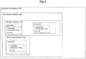
- FIG. 3 illustrates an exemplary physical configuration 300 of automation components 116a to 116i that may be implemented in the control system 100.
- the configuration 300 may represent a wireless FLN, such as the second network 108, including the first and second mesh networks 118a, 118b.
- the exemplary configuration 300 illustrates a structure in which the first mesh network 118a includes two zones 302 and 304 and the second mesh network 118b includes the zone 306.
- the zones include automation components 116a to 116i.
- zone 302 includes automation components 116a to 116c
- zone 304 includes automation components 116d to 116f
- zone 306 includes automation components 116g to 116i.
- Zones, mesh networks and automation components may be deployed within the structure in any know manner or configuration to provide sensor coverage for any space of interest therein.
- the automation components 116a to 116i may, in operation within the control system 100, be configured to control and monitor building systems and functions such as temperature, air flow, etc.
- the deployed automation components 116a to 116i are required to communicate with each other and, for example, the controller 106, the field panel 120 and/or the automation component 126.
- FIG. 4 illustrates an exemplary embodiment of the mobile tool or device 400 that may be utilized in cooperation with the one or more of the automation components 116a to 116i to perform site surveys, commission and diagnostic functions related to the configuration 300 and the control system 100.
- the mobile device 400 may be, for example, a laptop computer, a personal digital assistant (PDA) or smart phone utilizing, for example, Advanced RISC Machine (ARM) architecture or any other system architecture or configuration.
- the mobile device 400 in this exemplary embodiment, may utilize one or more operating systems (OS) or kernels such as, for example, PALM OS®, MICROSOFT MOBILE®, BLACKBERRY OS®, SYMBIAN OS® and/or an open LINUXTM OS.
- OS operating systems
- kernels such as, for example, PALM OS®, MICROSOFT MOBILE®, BLACKBERRY OS®, SYMBIAN OS® and/or an open LINUXTM OS.
- These or other well known operating systems could allow programmers to create a wide variety of programs, software and/or applications for use with the mobile device 400.
- the mobile device 400 may include a touch screen 402 for entering and/or viewing configuration information or data, a memory card slot 404 for data storage and memory expansion.
- the memory card slot 404 may further be utilized with specialized cards and plug-in devices such as, for example, a wireless networking card, to expand the capabilities of functionality of the mobile device 400.
- the mobile device 400 may include an antenna 406 to facility connectivity via one or more communication protocols such as: WiFi (WLAN); Bluetooth or other personal area network (PAN) standard; cellular communications and/or any other communication standard disclosed herein or foreseeable.
- the mobile device 400 may further include an infrared (IR) port 408 for communication via the Infrared Data association (IrDA) standard.
- IR infrared
- the mobile device 400 may be configured and designed with a communication component similar to, and compatible with, the communication component 210 shown and discussed in connection with FIG. 2 .
- the communication components utilized within the one or more of the automation components and the mobile device 400 may be selected and configured to be inter-compatible and compliant with any one of the communication protocols or standards discussed herein.
- the mobile device 400 may, in an embodiment, include or incorporate the components, elements and/or functionality deployed within the automation component 200 shown in FIG. 2 .
- Hard keys 410a to 410d may be provided to allow direct access to predefined functions or entrance of information via a virtual keyboard provided via the touch screen 402.
- the number and configuration of the hard keys may be varied to provide, for example, a full QWERTY keyboard, a numeric keyboard or any other desired arrangement.
- the mobile device 400 may further include a trackball 412, toggle or other navigation input for interaction with emergency information or data presented on the touch screen 402.
- the mobile device 400 may be configured to communicate with the deployed automation components 116a to 116i and one or more of the controller 106, the field panel 120 and/or the automation component 126. Moreover, the mobile device 400 may be configured to communicate with the battery powered or "sleeping" devices, e.g., one or more of the automation components 116a to 116i, utilizing a special or dedicated "WAKEUP" command which may be transmitted directly from the mobile device 400 or via the controller 106, the field panel 120 and/or the automation component 126 associated with the sleeping automation component of interest.
- the battery powered or "sleeping" devices e.g., one or more of the automation components 116a to 116i, utilizing a special or dedicated "WAKEUP" command which may be transmitted directly from the mobile device 400 or via the controller 106, the field panel 120 and/or the automation component 126 associated with the sleeping automation component of interest.
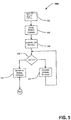
- FIG. 5 illustrates a flowchart 500 detailing the exemplary operation of the mobile device 400 within the configuration 300.
- the flowchart 500 illustrates an exemplary method or algorithm for communicating with one or more of the automation components 116a to 116i (see FIG. 3 ) which may be inactive/asleep, e.g., the internal components of the automation components 116a including components 202, 204, 210 and 220.
- the method provides for communication with one or more of the automation components 116a to 116i either directly or via the controller 106, the field panel 120 and/or the automation component 126, etc.
- the disclosed communication may include a specialized "WAKEUP" command configured to alter or modify the inactive or sleep schedule of the automation component(s) 116a to 116i.
- the mobile device 400 may communicate the special or dedicated WAKEUP command to all of the sleeping or inactive automation components 116a to 116i within the mesh networks 118a and 118b.
- the WAKEUP command may specify how frequently one or more of the automation components 116a to 116i transitions for "sleep" mode to "awake” mode to communicate with the mobile device 400 and how long a normal sleep/wake schedule should be overridden by the schedule communicated by the WAKEUP command. For example, in order to conserve battery power one or more of the automation components 116a to 116i may activate once every sixty (60) seconds.
- the WAKEUP command communicate by the mobile device 400 may be received and cached by one or more of the full function devices such as the controller 106, the field panel 120 and/or the automation component 126 shown in FIGS. 1 and 3 .
- the stored or cached WAKEUP command may, in turn, be communicated to one or more of the automation components 116a to 116i which may be asleep or inactive when the WAKEUP command was initially communicated.
- the WAKEUP command may be delivered.
- the automation components 116a to 116i may respond to the received WAKEUP command.
- the WAKEUP command may include instructions and values for altering the activity schedules for the automation components 116a to 116i.
- the WAKEUP command may direct one or more of the automation components 116a to 116i to activate once a second and/or to remain awake for thirty (30) seconds out of every sixty (60) seconds, e.g., activate once every two (2) seconds.
- the WAKEUP command may direct one or more of the automation components 116a to 116i to remain awake continuously for a period of time, until commanded to resume a normal activity schedule.
- the automation component 116a may be commanded, via the WAKEUP command, to activate once a second for a duration of twenty (20) minutes.
- a timer typically a clock timer associated with the processor 202, may be utilized to determine if the allotted duration of twenty (20) minutes has elapsed. If the period or duration has not elapsed, then at block 510, the automation components 116a from the previous example, may continue to implement the altered activity schedule and evaluate the duration at the block 508. If the period or duration has elapsed, then at block 512, the automation components 116a from the previous example, may return to the normal or standard activity schedule originally implemented before receipt of the WAKEUP command.
- the mobile device 400 may establish a direct communication link with the automation components 116a to 116i.
- the direct communication link eliminates the need for the controller 106, the field panel 120 and/or the automation component 126 to cache and store data from the automation components 116a to 116i which, in turn, shortens the overall communication time.
- the shorten overall communication time may extend the battery life of the reduced function device, automation component 116a in this example, because entire message may be sent as opposed to multiple partial messages.
- the mobile device 400 receives more accurate information via the direct communication link as opposed to delayed data cached and stored on the controller 106, the field panel 120 and/or the automation component 126.
- the reduced function device may experience extended battery life because it can temporarily remain in an active state to communicate and/or receive instructions, etc. In this way, the reduced function device does not have to continually power up and/or activate to poll for messages, rather the reduced function device may typically maintain, i.e., when not modified by the WAKEUP command, a power saving routine that extends the sleeping device battery life.
Landscapes
- Engineering & Computer Science (AREA)
- Computer Networks & Wireless Communication (AREA)
- Signal Processing (AREA)
- Multimedia (AREA)
- Automation & Control Theory (AREA)
- Mobile Radio Communication Systems (AREA)
- Selective Calling Equipment (AREA)
Claims (17)
- Verfahren zum Kommunizieren mit Automatisierungskomponenten (116), die für eine Verwendung innerhalb eines Gebäudeautomationssystems ausgelegt sind, wobei das Gebäudeautomationssystem ein erstes Netzwerk, das ein Automationsebenennetzwerk oder ein Managementebenennetzwerk ist, welches ein erstes Feld-Panel aufweist, ein zweites Netzwerk, das über einen Controller mit dem ersten Netzwerk verbunden ist, wobei das zweite Netzwerk ein Feldebenennetzwerk ist und ein zweites Feld-Panel umfasst, und eine Vielzahl von Automatisierungskomponenten, die Maschennetzwerke bilden, welche jeweils einen oder mehrere Bereiche abdecken und mit den Feld-Panels und dem Controller kommunizieren, umfasst, wobei das Verfahren umfasst:a) Übermitteln (502) eines speziellen oder dedizierten WAKEUP-Befehls von einem Mobilgerät (400) an einen Controller;b) Cachen (504) des empfangenen WAKEUP-Befehls am Controller;c) Bestimmen, am Controller, eines ersten Kommunikationsplans, wobei der erste Kommunikationsplan dafür ausgelegt ist, einen von einer Automatisierungskomponente zu verwendenden Aktivitätsplan zu steuern, um festzulegen, wie häufig die Automatisierungskomponente vom Schlafmodus zum Wachmodus übergeht, um mit dem Mobilgerät zu kommunizieren;d) Übermitteln, vom Controller aus, des gecachten WAKEUP-Befehls einschließlich des ersten Kommunikationsplans an die Automatisierungskomponente, wobei die Automatisierungskomponente gegenwärtig einen zweiten Kommunikationsplan implementiert, um den Aktivitätsplan zu steuern;e) Empfangen des gecachten WAKEUP-Befehls einschließlich des ersten Kommunikationsplans an der Automatisierungskomponente, wobei das Empfangen beinhaltet, dass eine schlafende Automatisierungskomponente gemäß dem zweiten Aktivitätsplan aufwacht, wobei sie ihren zugeordneten Controller abfragt und mit ihm kommuniziert, um eventuelle im Controller gespeicherte Nachrichten, Befehle und/oder Anweisungen zu übertragen, welche möglicherweise für die Automatisierungskomponente bestimmt waren;f) Anpassen, in Reaktion auf den empfangenen Aktivierungsbefehl, des zweiten Kommunikationsplans der Automatisierungskomponente, so dass er gleich dem übermittelten ersten Kommunikationsplan ist, wobei der Aktivitätsplan eine Kommunikationsfrequenz in Reaktion auf die Anpassung erhöht;g) Herstellen einer direkten Kommunikationsverbindung zwischen dem Mobilgerät und der Automatisierungskomponente.
- Verfahren nach Anspruch 1, wobei das Bestimmen des ersten Kommunikationsplans das Identifizieren einer Ziel-Kommunikationsfrequenz beinhaltet.
- Verfahren nach Anspruch 2, wobei das Identifizieren einer Ziel-Kommunikationsfrequenz das Identifizieren einer Dauer beinhaltet.
- Verfahren nach Anspruch 1, wobei der Aktivitätsplan eine erste Periode, die einer inaktiven Periode zugeordnet ist, und eine zweite Periode, die einer aktiven Periode zugeordnet ist, aufweist, wobei die erste Periode länger als die zweite Periode ist.
- Verfahren nach Anspruch 1, wobei der erste Kommunikationsplan die Automatisierungskomponente anweist, sich einmal pro Sekunde zur Kommunikation zu aktivieren.
- Verfahren nach Anspruch 1, welches ferner umfasst:Herstellen einer direkten Kommunikationsverbindung zwischen der Automatisierungskomponente und einem anderen Gerät.
- Verfahren nach Anspruch 1, wobei das andere Gerät ein Mobilgerät ist.
- Verfahren nach Anspruch 1, wobei das Übermitteln des ersten Kommunikationsplans an die Automatisierungskomponente das Übermitteln des ersten Kommunikationsplans an die Automatisierungskomponente über eine zweite Automatisierungskomponente beinhaltet.
- Gerät nach Anspruch 1, welches ferner umfasst:Definieren einer Dauer, während der der erste Kommunikationsplan gleich dem zweiten Kommunikationsplan ist.
- System zur Mobilkommunikation mit Automatisierungskomponenten (116) innerhalb eines Gebäudeautomationssystems, wobei das System ein erstes Netzwerk umfasst, das ein Automationsebenennetzwerk oder ein Managementebenennetzwerk ist, welches ein erstes Feld-Panel aufweist, ein zweites Netzwerk, das über einen Controller mit dem ersten Netzwerk verbunden ist, wobei das zweite Netzwerk ein Feldebenennetzwerk ist und ein zweites Feld-Panel umfasst, und eine Vielzahl von Automatisierungskomponenten, die Maschennetzwerke bilden, welche jeweils einen oder mehrere Bereiche abdecken und mit den Feld-Panels und dem Controller kommunizieren, umfassend:ein Mobilgerät (400), das einen Prozessor aufweist, der mit einem Speicher in Kommunikation steht, wobei der Prozessor dafür ausgelegt ist, den speziellen oder dedizierten WAKEUP-Befehl von dem Mobilgerät an einen Controller zu übermitteln;einen Controller, der dafür ausgelegt ist:den WAKEUP-Befehl zu empfangen (504), der von dem Mobilgerät (400) übermittelt wurde;den empfangenen WAKEUP-Befehl am Controller zu cachen;einen ersten Kommunikationsplan zu bestimmen, wobei der erste Kommunikationsplan dafür ausgelegt ist, einen von einer Automatisierungskomponente zu verwendenden Aktivitätsplan zu steuern, um festzulegen, wie häufig die Automatisierungskomponente vom Schlafmodus zum Wachmodus übergeht, um mit dem Mobilgerät zu kommunizieren;den ersten Kommunikationsplan über eine Drahtloskommunikationskomponente an die Automatisierungskomponente zu übermitteln, wobei die Automatisierungskomponente gegenwärtig einen zweiten Kommunikationsplan implementiert, um den Aktivitätsplan zu steuern;wobei die Automatisierungskomponente den gecachten WAKEUP-Befehl und den ersten Kommunikationsplan empfängt, wobei das Empfangen beinhaltet, dass eine schlafende Automatisierungskomponente gemäß dem zweiten Aktivitätsplan aufwacht, wobei sie ihren zugeordneten Controller abfragt und mit ihm kommuniziert, um eventuelle im Controller gespeicherte Nachrichten, Befehle und/oder Anweisungen zu übertragen, welche möglicherweise für die Automatisierungskomponente bestimmt waren,um den zweiten Kommunikationsplan innerhalb der Automatisierungskomponente anzupassen, so dass er gleich dem übermittelten ersten Kommunikationsplan ist, wobei der Aktivitätsplan eine Kommunikationsfrequenz in Reaktion auf die Anpassung erhöht; undwobei das Mobilgerät eine direkte Kommunikationsverbindung mit der Automatisierungskomponente herstellt.
- System nach Anspruch 10, wobei der Prozessor dafür ausgelegt ist, eine Ziel-Kommunikationsfrequenz zu verwenden, um den ersten Kommunikationsplan zu bestimmen.
- System nach Anspruch 11, wobei die Ziel-Kommunikationsfrequenz eine Dauer beinhaltet.
- System nach Anspruch 10, wobei der Aktivitätsplan eine erste Periode, die einer inaktiven Periode zugeordnet ist, und eine zweite Periode, die einer aktiven Periode zugeordnet ist, aufweist, wobei die erste Periode länger als die zweite Periode ist.
- System nach Anspruch 10, wobei der erste Kommunikationsplan die Automatisierungskomponente anweist, sich einmal pro Sekunde zur Kommunikation zu aktivieren.
- System nach Anspruch 10, wobei die Drahtloskommunikationskomponente dafür ausgelegt ist, eine direkte Kommunikationsverbindung zu der Automatisierungskomponente herzustellen.
- System nach Anspruch 10, wobei der an die Automatisierungskomponente übermittelte erste Kommunikationsplan über eine zweite Automatisierungskomponente an die Automatisierungskomponente übermittelt wird.
- System nach Anspruch 10, wobei der Prozessor ferner dafür ausgelegt ist, eine Dauer zu definieren, während der der erste Kommunikationsplan gleich dem zweiten Kommunikationsplan ist.
Applications Claiming Priority (4)
| Application Number | Priority Date | Filing Date | Title |
|---|---|---|---|
| US99444107P | 2007-09-20 | 2007-09-20 | |
| US99444307P | 2007-09-20 | 2007-09-20 | |
| US12/135,647 US9143332B2 (en) | 2006-10-31 | 2008-06-09 | Method and tool for wireless communications with sleeping devices in a wireless sensor control network |
| PCT/US2008/010747 WO2009038687A2 (en) | 2007-09-20 | 2008-09-15 | Method and tool for wireless communications with sleeping devices in a wireless sensor control network |
Publications (2)
| Publication Number | Publication Date |
|---|---|
| EP2193452A2 EP2193452A2 (de) | 2010-06-09 |
| EP2193452B1 true EP2193452B1 (de) | 2017-11-29 |
Family
ID=40468683
Family Applications (1)
| Application Number | Title | Priority Date | Filing Date |
|---|---|---|---|
| EP08831513.0A Active EP2193452B1 (de) | 2007-09-20 | 2008-09-15 | Verfahren und system zur drahtlosen kommunikation mit geräten im schlafmodus in einem sensorsteuerungsnetz |
Country Status (7)
| Country | Link |
|---|---|
| US (1) | US9143332B2 (de) |
| EP (1) | EP2193452B1 (de) |
| KR (1) | KR101280683B1 (de) |
| CN (1) | CN101939949B (de) |
| BR (1) | BRPI0816416B1 (de) |
| CA (1) | CA2700106C (de) |
| WO (1) | WO2009038687A2 (de) |
Families Citing this family (13)
| Publication number | Priority date | Publication date | Assignee | Title |
|---|---|---|---|---|
| US8024055B1 (en) | 2004-05-15 | 2011-09-20 | Sonos, Inc. | Method and system for controlling amplifiers |
| US8971223B2 (en) * | 2010-05-11 | 2015-03-03 | Qualcomm Incorporated | Wireless personal area network coordinator |
| US8552857B2 (en) | 2010-10-14 | 2013-10-08 | Honeywell International Inc. | Failsafe signal transmission for wireless sensor mesh |
| US20120047921A1 (en) | 2010-11-22 | 2012-03-01 | General Electric Company | Dsm enabling of electro mechanically controlled refrigeration systems |
| US8504216B2 (en) * | 2010-11-22 | 2013-08-06 | General Electric Company | DSM enabling of electro mechanically controlled refrigeration systems |
| EP2538609B1 (de) * | 2011-06-22 | 2016-01-06 | Siemens Aktiengesellschaft | Energieeinsparung in einem netzwerkknoten eines automatisierungsnetzwerks |
| US9036489B2 (en) * | 2012-06-22 | 2015-05-19 | Honey International Inc. | Access point synchronization in Wi-Fi fire detection systems |
| US9477239B2 (en) | 2012-07-26 | 2016-10-25 | Honeywell International Inc. | HVAC controller with wireless network based occupancy detection and control |
| US9594384B2 (en) | 2012-07-26 | 2017-03-14 | Honeywell International Inc. | Method of associating an HVAC controller with an external web service |
| EP2849382A1 (de) * | 2013-09-13 | 2015-03-18 | Assa Abloy Ip Ab | Drahtlose Steuerung in einem Gebäudeautomatisierungssystem |
| US9244516B2 (en) | 2013-09-30 | 2016-01-26 | Sonos, Inc. | Media playback system using standby mode in a mesh network |
| US9609056B2 (en) * | 2014-03-29 | 2017-03-28 | Google Technology Holdings LLC | Methods for obtaining content from a peer device |
| US10261569B2 (en) * | 2015-05-01 | 2019-04-16 | Qualcomm Incorporated | Universal serial bus (USB) host and client devices for supporting scheduled low-power operations |
Family Cites Families (11)
| Publication number | Priority date | Publication date | Assignee | Title |
|---|---|---|---|---|
| US7064671B2 (en) * | 2000-06-23 | 2006-06-20 | Fisher Controls International Llc | Low power regulator system and method |
| KR100433556B1 (ko) * | 2002-08-08 | 2004-05-31 | 삼성전자주식회사 | 애드혹 네트워크상의 링크 상태 동기화 방법, 장치 및데이터구조 |
| US7183899B2 (en) * | 2004-03-15 | 2007-02-27 | Global Gate Technologies, Inc. | Remotely monitored and controlled building automation system |
| DE102004020393A1 (de) * | 2004-04-23 | 2005-11-10 | Endress + Hauser Gmbh + Co. Kg | Funkmodul für Feldgeräte der Automatisierungstechnik |
| US8055387B2 (en) * | 2005-08-22 | 2011-11-08 | Trane International Inc. | Building automation system data management |
| US8050801B2 (en) * | 2005-08-22 | 2011-11-01 | Trane International Inc. | Dynamically extensible and automatically configurable building automation system and architecture |
| JP5101523B2 (ja) | 2006-01-11 | 2012-12-19 | フィッシャー−ローズマウント システムズ, インコーポレイテッド | 低電力無線メッシュネットワークにおけるフィールドデバイスの選択的起動 |
| WO2007104152A2 (en) | 2006-03-14 | 2007-09-20 | Jamie Hackett | Long-range radio frequency receiver-controller module and wireless control system comprising same |
| US8059009B2 (en) * | 2006-09-15 | 2011-11-15 | Itron, Inc. | Uplink routing without routing table |
| US20080082183A1 (en) * | 2006-09-29 | 2008-04-03 | Johnson Controls Technology Company | Building automation system with automated component selection for minimum energy consumption |
| US20090065596A1 (en) * | 2007-05-09 | 2009-03-12 | Johnson Controls Technology Company | Systems and methods for increasing building space comfort using wireless devices |
-
2008
- 2008-06-09 US US12/135,647 patent/US9143332B2/en active Active
- 2008-09-15 CA CA2700106A patent/CA2700106C/en active Active
- 2008-09-15 EP EP08831513.0A patent/EP2193452B1/de active Active
- 2008-09-15 WO PCT/US2008/010747 patent/WO2009038687A2/en not_active Ceased
- 2008-09-15 CN CN200880116824.8A patent/CN101939949B/zh active Active
- 2008-09-15 KR KR1020107008542A patent/KR101280683B1/ko not_active Expired - Fee Related
- 2008-09-15 BR BRPI0816416-9A patent/BRPI0816416B1/pt active IP Right Grant
Also Published As
| Publication number | Publication date |
|---|---|
| CA2700106A1 (en) | 2009-03-26 |
| CN101939949B (zh) | 2014-07-02 |
| EP2193452A2 (de) | 2010-06-09 |
| WO2009038687A2 (en) | 2009-03-26 |
| BRPI0816416B1 (pt) | 2020-09-15 |
| US9143332B2 (en) | 2015-09-22 |
| CA2700106C (en) | 2014-07-15 |
| US20090082885A1 (en) | 2009-03-26 |
| KR101280683B1 (ko) | 2013-07-02 |
| CN101939949A (zh) | 2011-01-05 |
| WO2009038687A3 (en) | 2010-06-24 |
| KR20100066567A (ko) | 2010-06-17 |
Similar Documents
| Publication | Publication Date | Title |
|---|---|---|
| CA2700106C (en) | Method and tool for wireless communications with sleeping devices in a wireless sensor control network | |
| US20090083416A1 (en) | Methods to verify wireless node placement for reliable communication in wireless sensor control networks | |
| US8224282B2 (en) | Method and device to manage power of wireless multi-sensor devices | |
| US8264371B2 (en) | Method and device for communicating change-of-value information in a building automation system | |
| CA2661915C (en) | Method and device for binding an automation component within a building automation system | |
| CA2662014C (en) | Binding methods and devices in a building automation system | |
| US7831282B2 (en) | Wireless node providing improved battery power consumption and system employing the same | |
| US20180132183A1 (en) | Wireless device power saving system and method | |
| CN101401133B (zh) | 低功率无线网状网络中现场设备的选择性激活 | |
| KR101120356B1 (ko) | 무선 노드 오토 리셋 기능 | |
| CN103576664A (zh) | 一种智能家居系统中传送值变化信息的自动化组件和方法 | |
| US10542582B1 (en) | Wireless communication with adaptive responsiveness | |
| CA2836941C (en) | Binding methods and devices in a building automation system |
Legal Events
| Date | Code | Title | Description |
|---|---|---|---|
| PUAI | Public reference made under article 153(3) epc to a published international application that has entered the european phase |
Free format text: ORIGINAL CODE: 0009012 |
|
| 17P | Request for examination filed |
Effective date: 20100319 |
|
| AK | Designated contracting states |
Kind code of ref document: A2 Designated state(s): AT BE BG CH CY CZ DE DK EE ES FI FR GB GR HR HU IE IS IT LI LT LU LV MC MT NL NO PL PT RO SE SI SK TR |
|
| AX | Request for extension of the european patent |
Extension state: AL BA MK RS |
|
| R17D | Deferred search report published (corrected) |
Effective date: 20100624 |
|
| DAX | Request for extension of the european patent (deleted) | ||
| 17Q | First examination report despatched |
Effective date: 20140411 |
|
| RAP1 | Party data changed (applicant data changed or rights of an application transferred) |
Owner name: SIEMENS INDUSTRY, INC. |
|
| GRAP | Despatch of communication of intention to grant a patent |
Free format text: ORIGINAL CODE: EPIDOSNIGR1 |
|
| STAA | Information on the status of an ep patent application or granted ep patent |
Free format text: STATUS: GRANT OF PATENT IS INTENDED |
|
| INTG | Intention to grant announced |
Effective date: 20170623 |
|
| GRAS | Grant fee paid |
Free format text: ORIGINAL CODE: EPIDOSNIGR3 |
|
| GRAA | (expected) grant |
Free format text: ORIGINAL CODE: 0009210 |
|
| STAA | Information on the status of an ep patent application or granted ep patent |
Free format text: STATUS: THE PATENT HAS BEEN GRANTED |
|
| AK | Designated contracting states |
Kind code of ref document: B1 Designated state(s): AT BE BG CH CY CZ DE DK EE ES FI FR GB GR HR HU IE IS IT LI LT LU LV MC MT NL NO PL PT RO SE SI SK TR |
|
| REG | Reference to a national code |
Ref country code: GB Ref legal event code: FG4D |
|
| REG | Reference to a national code |
Ref country code: CH Ref legal event code: EP Ref country code: CH Ref legal event code: NV Representative=s name: SIEMENS SCHWEIZ AG, CH |
|
| REG | Reference to a national code |
Ref country code: AT Ref legal event code: REF Ref document number: 951007 Country of ref document: AT Kind code of ref document: T Effective date: 20171215 |
|
| REG | Reference to a national code |
Ref country code: IE Ref legal event code: FG4D |
|
| REG | Reference to a national code |
Ref country code: DE Ref legal event code: R096 Ref document number: 602008053193 Country of ref document: DE |
|
| REG | Reference to a national code |
Ref country code: SE Ref legal event code: TRGR |
|
| REG | Reference to a national code |
Ref country code: NL Ref legal event code: MP Effective date: 20171129 |
|
| REG | Reference to a national code |
Ref country code: LT Ref legal event code: MG4D |
|
| REG | Reference to a national code |
Ref country code: AT Ref legal event code: MK05 Ref document number: 951007 Country of ref document: AT Kind code of ref document: T Effective date: 20171129 |
|
| PG25 | Lapsed in a contracting state [announced via postgrant information from national office to epo] |
Ref country code: FI Free format text: LAPSE BECAUSE OF FAILURE TO SUBMIT A TRANSLATION OF THE DESCRIPTION OR TO PAY THE FEE WITHIN THE PRESCRIBED TIME-LIMIT Effective date: 20171129 Ref country code: NO Free format text: LAPSE BECAUSE OF FAILURE TO SUBMIT A TRANSLATION OF THE DESCRIPTION OR TO PAY THE FEE WITHIN THE PRESCRIBED TIME-LIMIT Effective date: 20180228 Ref country code: ES Free format text: LAPSE BECAUSE OF FAILURE TO SUBMIT A TRANSLATION OF THE DESCRIPTION OR TO PAY THE FEE WITHIN THE PRESCRIBED TIME-LIMIT Effective date: 20171129 Ref country code: LT Free format text: LAPSE BECAUSE OF FAILURE TO SUBMIT A TRANSLATION OF THE DESCRIPTION OR TO PAY THE FEE WITHIN THE PRESCRIBED TIME-LIMIT Effective date: 20171129 |
|
| PG25 | Lapsed in a contracting state [announced via postgrant information from national office to epo] |
Ref country code: GR Free format text: LAPSE BECAUSE OF FAILURE TO SUBMIT A TRANSLATION OF THE DESCRIPTION OR TO PAY THE FEE WITHIN THE PRESCRIBED TIME-LIMIT Effective date: 20180301 Ref country code: HR Free format text: LAPSE BECAUSE OF FAILURE TO SUBMIT A TRANSLATION OF THE DESCRIPTION OR TO PAY THE FEE WITHIN THE PRESCRIBED TIME-LIMIT Effective date: 20171129 Ref country code: LV Free format text: LAPSE BECAUSE OF FAILURE TO SUBMIT A TRANSLATION OF THE DESCRIPTION OR TO PAY THE FEE WITHIN THE PRESCRIBED TIME-LIMIT Effective date: 20171129 Ref country code: BG Free format text: LAPSE BECAUSE OF FAILURE TO SUBMIT A TRANSLATION OF THE DESCRIPTION OR TO PAY THE FEE WITHIN THE PRESCRIBED TIME-LIMIT Effective date: 20180228 Ref country code: AT Free format text: LAPSE BECAUSE OF FAILURE TO SUBMIT A TRANSLATION OF THE DESCRIPTION OR TO PAY THE FEE WITHIN THE PRESCRIBED TIME-LIMIT Effective date: 20171129 |
|
| PG25 | Lapsed in a contracting state [announced via postgrant information from national office to epo] |
Ref country code: NL Free format text: LAPSE BECAUSE OF FAILURE TO SUBMIT A TRANSLATION OF THE DESCRIPTION OR TO PAY THE FEE WITHIN THE PRESCRIBED TIME-LIMIT Effective date: 20171129 |
|
| PG25 | Lapsed in a contracting state [announced via postgrant information from national office to epo] |
Ref country code: SK Free format text: LAPSE BECAUSE OF FAILURE TO SUBMIT A TRANSLATION OF THE DESCRIPTION OR TO PAY THE FEE WITHIN THE PRESCRIBED TIME-LIMIT Effective date: 20171129 Ref country code: CZ Free format text: LAPSE BECAUSE OF FAILURE TO SUBMIT A TRANSLATION OF THE DESCRIPTION OR TO PAY THE FEE WITHIN THE PRESCRIBED TIME-LIMIT Effective date: 20171129 Ref country code: DK Free format text: LAPSE BECAUSE OF FAILURE TO SUBMIT A TRANSLATION OF THE DESCRIPTION OR TO PAY THE FEE WITHIN THE PRESCRIBED TIME-LIMIT Effective date: 20171129 Ref country code: CY Free format text: LAPSE BECAUSE OF FAILURE TO SUBMIT A TRANSLATION OF THE DESCRIPTION OR TO PAY THE FEE WITHIN THE PRESCRIBED TIME-LIMIT Effective date: 20171129 Ref country code: EE Free format text: LAPSE BECAUSE OF FAILURE TO SUBMIT A TRANSLATION OF THE DESCRIPTION OR TO PAY THE FEE WITHIN THE PRESCRIBED TIME-LIMIT Effective date: 20171129 |
|
| REG | Reference to a national code |
Ref country code: DE Ref legal event code: R097 Ref document number: 602008053193 Country of ref document: DE |
|
| PG25 | Lapsed in a contracting state [announced via postgrant information from national office to epo] |
Ref country code: PL Free format text: LAPSE BECAUSE OF FAILURE TO SUBMIT A TRANSLATION OF THE DESCRIPTION OR TO PAY THE FEE WITHIN THE PRESCRIBED TIME-LIMIT Effective date: 20171129 Ref country code: RO Free format text: LAPSE BECAUSE OF FAILURE TO SUBMIT A TRANSLATION OF THE DESCRIPTION OR TO PAY THE FEE WITHIN THE PRESCRIBED TIME-LIMIT Effective date: 20171129 |
|
| REG | Reference to a national code |
Ref country code: FR Ref legal event code: PLFP Year of fee payment: 11 |
|
| PLBE | No opposition filed within time limit |
Free format text: ORIGINAL CODE: 0009261 |
|
| STAA | Information on the status of an ep patent application or granted ep patent |
Free format text: STATUS: NO OPPOSITION FILED WITHIN TIME LIMIT |
|
| 26N | No opposition filed |
Effective date: 20180830 |
|
| PG25 | Lapsed in a contracting state [announced via postgrant information from national office to epo] |
Ref country code: SI Free format text: LAPSE BECAUSE OF FAILURE TO SUBMIT A TRANSLATION OF THE DESCRIPTION OR TO PAY THE FEE WITHIN THE PRESCRIBED TIME-LIMIT Effective date: 20171129 |
|
| PG25 | Lapsed in a contracting state [announced via postgrant information from national office to epo] |
Ref country code: MC Free format text: LAPSE BECAUSE OF FAILURE TO SUBMIT A TRANSLATION OF THE DESCRIPTION OR TO PAY THE FEE WITHIN THE PRESCRIBED TIME-LIMIT Effective date: 20171129 |
|
| REG | Reference to a national code |
Ref country code: BE Ref legal event code: MM Effective date: 20180930 |
|
| REG | Reference to a national code |
Ref country code: IE Ref legal event code: MM4A |
|
| PG25 | Lapsed in a contracting state [announced via postgrant information from national office to epo] |
Ref country code: LU Free format text: LAPSE BECAUSE OF NON-PAYMENT OF DUE FEES Effective date: 20180915 |
|
| PG25 | Lapsed in a contracting state [announced via postgrant information from national office to epo] |
Ref country code: IE Free format text: LAPSE BECAUSE OF NON-PAYMENT OF DUE FEES Effective date: 20180915 |
|
| PG25 | Lapsed in a contracting state [announced via postgrant information from national office to epo] |
Ref country code: BE Free format text: LAPSE BECAUSE OF NON-PAYMENT OF DUE FEES Effective date: 20180930 |
|
| PG25 | Lapsed in a contracting state [announced via postgrant information from national office to epo] |
Ref country code: MT Free format text: LAPSE BECAUSE OF NON-PAYMENT OF DUE FEES Effective date: 20180915 |
|
| PG25 | Lapsed in a contracting state [announced via postgrant information from national office to epo] |
Ref country code: TR Free format text: LAPSE BECAUSE OF FAILURE TO SUBMIT A TRANSLATION OF THE DESCRIPTION OR TO PAY THE FEE WITHIN THE PRESCRIBED TIME-LIMIT Effective date: 20171129 |
|
| PG25 | Lapsed in a contracting state [announced via postgrant information from national office to epo] |
Ref country code: HU Free format text: LAPSE BECAUSE OF FAILURE TO SUBMIT A TRANSLATION OF THE DESCRIPTION OR TO PAY THE FEE WITHIN THE PRESCRIBED TIME-LIMIT; INVALID AB INITIO Effective date: 20080915 Ref country code: PT Free format text: LAPSE BECAUSE OF FAILURE TO SUBMIT A TRANSLATION OF THE DESCRIPTION OR TO PAY THE FEE WITHIN THE PRESCRIBED TIME-LIMIT Effective date: 20171129 |
|
| PG25 | Lapsed in a contracting state [announced via postgrant information from national office to epo] |
Ref country code: IS Free format text: LAPSE BECAUSE OF FAILURE TO SUBMIT A TRANSLATION OF THE DESCRIPTION OR TO PAY THE FEE WITHIN THE PRESCRIBED TIME-LIMIT Effective date: 20180329 |
|
| PGFP | Annual fee paid to national office [announced via postgrant information from national office to epo] |
Ref country code: SE Payment date: 20220915 Year of fee payment: 15 |
|
| PGFP | Annual fee paid to national office [announced via postgrant information from national office to epo] |
Ref country code: IT Payment date: 20220926 Year of fee payment: 15 |
|
| REG | Reference to a national code |
Ref country code: SE Ref legal event code: EUG |
|
| PG25 | Lapsed in a contracting state [announced via postgrant information from national office to epo] |
Ref country code: SE Free format text: LAPSE BECAUSE OF NON-PAYMENT OF DUE FEES Effective date: 20230916 |
|
| PG25 | Lapsed in a contracting state [announced via postgrant information from national office to epo] |
Ref country code: IT Free format text: LAPSE BECAUSE OF NON-PAYMENT OF DUE FEES Effective date: 20230915 |
|
| PG25 | Lapsed in a contracting state [announced via postgrant information from national office to epo] |
Ref country code: IT Free format text: LAPSE BECAUSE OF NON-PAYMENT OF DUE FEES Effective date: 20230915 |
|
| PGFP | Annual fee paid to national office [announced via postgrant information from national office to epo] |
Ref country code: FR Payment date: 20250915 Year of fee payment: 18 |
|
| REG | Reference to a national code |
Ref country code: CH Ref legal event code: U11 Free format text: ST27 STATUS EVENT CODE: U-0-0-U10-U11 (AS PROVIDED BY THE NATIONAL OFFICE) Effective date: 20251210 |
|
| PGFP | Annual fee paid to national office [announced via postgrant information from national office to epo] |
Ref country code: DE Payment date: 20251120 Year of fee payment: 18 |
|
| PGFP | Annual fee paid to national office [announced via postgrant information from national office to epo] |
Ref country code: GB Payment date: 20251002 Year of fee payment: 18 |
|
| PGFP | Annual fee paid to national office [announced via postgrant information from national office to epo] |
Ref country code: CH Payment date: 20251210 Year of fee payment: 18 |