EP2193475B1 - Optimisation du rapport cyclique ou de l'alimentation d'un lecteur rfid afin de préserver la durée de vie de la batterie - Google Patents
Optimisation du rapport cyclique ou de l'alimentation d'un lecteur rfid afin de préserver la durée de vie de la batterie Download PDFInfo
- Publication number
- EP2193475B1 EP2193475B1 EP08834167A EP08834167A EP2193475B1 EP 2193475 B1 EP2193475 B1 EP 2193475B1 EP 08834167 A EP08834167 A EP 08834167A EP 08834167 A EP08834167 A EP 08834167A EP 2193475 B1 EP2193475 B1 EP 2193475B1
- Authority
- EP
- European Patent Office
- Prior art keywords
- reader
- duty cycle
- time
- rfid tag
- tag
- Prior art date
- Legal status (The legal status is an assumption and is not a legal conclusion. Google has not performed a legal analysis and makes no representation as to the accuracy of the status listed.)
- Not-in-force
Links
Images


Classifications
-
- G—PHYSICS
- G06—COMPUTING OR CALCULATING; COUNTING
- G06K—GRAPHICAL DATA READING; PRESENTATION OF DATA; RECORD CARRIERS; HANDLING RECORD CARRIERS
- G06K7/00—Methods or arrangements for sensing record carriers, e.g. for reading patterns
- G06K7/10—Methods or arrangements for sensing record carriers, e.g. for reading patterns by electromagnetic radiation, e.g. optical sensing; by corpuscular radiation
- G06K7/10009—Methods or arrangements for sensing record carriers, e.g. for reading patterns by electromagnetic radiation, e.g. optical sensing; by corpuscular radiation sensing by radiation using wavelengths larger than 0.1 mm, e.g. radio-waves or microwaves
- G06K7/10316—Methods or arrangements for sensing record carriers, e.g. for reading patterns by electromagnetic radiation, e.g. optical sensing; by corpuscular radiation sensing by radiation using wavelengths larger than 0.1 mm, e.g. radio-waves or microwaves using at least one antenna particularly designed for interrogating the wireless record carriers
- G06K7/10346—Methods or arrangements for sensing record carriers, e.g. for reading patterns by electromagnetic radiation, e.g. optical sensing; by corpuscular radiation sensing by radiation using wavelengths larger than 0.1 mm, e.g. radio-waves or microwaves using at least one antenna particularly designed for interrogating the wireless record carriers the antenna being of the far field type, e.g. HF types or dipoles
-
- G—PHYSICS
- G06—COMPUTING OR CALCULATING; COUNTING
- G06K—GRAPHICAL DATA READING; PRESENTATION OF DATA; RECORD CARRIERS; HANDLING RECORD CARRIERS
- G06K7/00—Methods or arrangements for sensing record carriers, e.g. for reading patterns
- G06K7/0008—General problems related to the reading of electronic memory record carriers, independent of its reading method, e.g. power transfer
-
- G—PHYSICS
- G06—COMPUTING OR CALCULATING; COUNTING
- G06K—GRAPHICAL DATA READING; PRESENTATION OF DATA; RECORD CARRIERS; HANDLING RECORD CARRIERS
- G06K7/00—Methods or arrangements for sensing record carriers, e.g. for reading patterns
- G06K7/10—Methods or arrangements for sensing record carriers, e.g. for reading patterns by electromagnetic radiation, e.g. optical sensing; by corpuscular radiation
- G06K7/10009—Methods or arrangements for sensing record carriers, e.g. for reading patterns by electromagnetic radiation, e.g. optical sensing; by corpuscular radiation sensing by radiation using wavelengths larger than 0.1 mm, e.g. radio-waves or microwaves
- G06K7/10198—Methods or arrangements for sensing record carriers, e.g. for reading patterns by electromagnetic radiation, e.g. optical sensing; by corpuscular radiation sensing by radiation using wavelengths larger than 0.1 mm, e.g. radio-waves or microwaves setting parameters for the interrogator, e.g. programming parameters and operating modes
- G06K7/10207—Methods or arrangements for sensing record carriers, e.g. for reading patterns by electromagnetic radiation, e.g. optical sensing; by corpuscular radiation sensing by radiation using wavelengths larger than 0.1 mm, e.g. radio-waves or microwaves setting parameters for the interrogator, e.g. programming parameters and operating modes parameter settings related to power consumption of the interrogator
-
- G—PHYSICS
- G06—COMPUTING OR CALCULATING; COUNTING
- G06K—GRAPHICAL DATA READING; PRESENTATION OF DATA; RECORD CARRIERS; HANDLING RECORD CARRIERS
- G06K7/00—Methods or arrangements for sensing record carriers, e.g. for reading patterns
- G06K7/10—Methods or arrangements for sensing record carriers, e.g. for reading patterns by electromagnetic radiation, e.g. optical sensing; by corpuscular radiation
- G06K7/10009—Methods or arrangements for sensing record carriers, e.g. for reading patterns by electromagnetic radiation, e.g. optical sensing; by corpuscular radiation sensing by radiation using wavelengths larger than 0.1 mm, e.g. radio-waves or microwaves
- G06K7/10198—Methods or arrangements for sensing record carriers, e.g. for reading patterns by electromagnetic radiation, e.g. optical sensing; by corpuscular radiation sensing by radiation using wavelengths larger than 0.1 mm, e.g. radio-waves or microwaves setting parameters for the interrogator, e.g. programming parameters and operating modes
- G06K7/10217—Methods or arrangements for sensing record carriers, e.g. for reading patterns by electromagnetic radiation, e.g. optical sensing; by corpuscular radiation sensing by radiation using wavelengths larger than 0.1 mm, e.g. radio-waves or microwaves setting parameters for the interrogator, e.g. programming parameters and operating modes parameter settings controlling the transmission power of the interrogator
Definitions
- the inventions relate in general to the use of radio frequency identification (RFID) tags and RFID tag readers (also known as “interrogators”).
- RFID radio frequency identification
- RFID tag readers also known as “interrogators”
- the inventions relate to the configuration and operation of battery-powered RFID tag readers.
- Portable RFID tag readers typically draw high current to provide output power required to read RFID tags at a distance. In battery powered devices, high current quickly depletes the system battery. Duty cycles are typically implemented such that the average current is within acceptable limit. As the duty cycle is reduced, there becomes a point at which reader aggressiveness is significantly reduced. Reader aggressiveness relates to how quickly and easily the reader can read a tag from the user's perspective. Aggressive readers do not appear to the user to be sluggish or incapable of reliable operation at the intended read distance.
- Radio frequency identification (RFID) tags are electronic devices that may be affixed to items whose presence is to be detected and/or monitored. RFID tags are classified based on standards defined by national and international standards bodies (e.g., EPCGlobal and ISO). Standard tag classes include Class 0, Class 1, and Class 1 Generation 2 (referred to herein as "Gen 2"). The presence of an RFID tag, and therefore the presence of the item to which the tag is affixed, may be checked and monitored wirelessly by an "RFID reader”, also known as a “reader-interrogator”, “interrogator”, or simply “reader.” Readers typically have one or more antennas for transmitting radio frequency signals to RFID tags and receiving responses from them. An RFID tag within range of a reader-transmitted signal responds with a signal including a unique identifier.
- EP 0 944 014 A2 describes detecting an RF tag in proximity to an RFID reader operating in a reduced power state.
- EP 0 944 015 A2 describes reading RF transponders at varying ranges by directing transponder that have already been energized and read to stop responding to future energizing events.
- the present invention proposes an RFID reader according to claim 1 and a method according to claim 2 for operating the FRID reader.
- the claimed method optimizes power consumption of an RFID tag reader. Utilizing the methods presented herein a reader optimizes its power consumption such that it uses more average power during times when it is more likely that a successful read will occur and utilizes less average power during periods when a successful read is less likely to occur.
- An algorithm is presented that changes the duty cycle in accordance with predetermined criteria. While presently preferred embodiments of this invention concentrate on changing the duty cycle as the means to optimize reader aggressiveness verses power consumption, changing the peak power can also be used. (again based on the times when it is more likely that a successful read will occur) Changing the power greatly affects the range of the reader but it can still be used to exploit the probability concepts presented.
- the reader learns when the probability of a tag being in range is high and adjusts the duty cycle accordingly.
- the reader can learn user habits such as a user habitually triggering the reader then pointing the reader at the tag a second or two later.
- the reader can learn how long to wait after failing multiple read attempts due to interference from other RFID readers.
- Teen skilled in the art could expand this to provide a cooperation scheme between nearby readers. Such a scheme could use duty cycle adjustments and/or a random hold off time to reduce wasted RF transmissions.
- FIG. 1 illustrates an environment in which RFID tag readers communicate with a population of RFID tags.
- FIG. 2 is a block diagram of an example RFID reader.
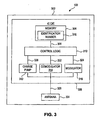
- FIG. 3 is a schematic block diagram of an example radio frequency identification (RFID) tag.
- RFID radio frequency identification
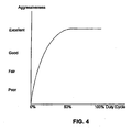
- FIG. 4 is a graphical representation of duty cycle versus aggressiveness.
- FIG 5 is a graphical representation explaining some of the terms used to describe the inventions.
- FIG. 6 is a graphical representation of the probability of a successful read following a trigger during trigger mode operation.
- FIG. 7 is a graphical representation of duty cycle versus time during a read attempt (trigger mode operation).
- FIG. 8 is a graphical representation of autonomous mode operation indicating duty cycle after an RFID tag has been found to be in range.
- FIG. 9 is a flowchart indicating an example of an algorithm and method of operation according to the inventions.
- FIG. 1 illustrates an environment 100 where RFID tag readers 104 (readers 104a and 104b shown in FIG. 1 ) communicate with an exemplary population 120 of RFID tags 102.
- the population 120 of tags includes seven tags 102a-120g.
- a population 120 may include any number of tags 102.
- Environment 100 includes any number of one or more readers 104.
- environment 100 includes a first reader 104a and a second reader 104b.
- Readers 104a and/or 104b may be requested by an external application to address the population of tags 120.
- reader 104a and/or reader 104b may have internal logic that initiates communication, or may have a trigger mechanism that an operator of a reader 104 uses to initiate communication.
- Readers 104a and 104b may also communicate with each other in a reader network (see FIG. 2 ).
- a reader 104 may be continuously commercial powered by attachment to power mains or it may be battery powered. The inventions described herein are particularly applicable to battery powered readers.
- reader 104a "reads" tags 120 by transmitting an interrogation signal 110a to the population of tags 120.
- Interrogation signals may have primary signal at a particular carrier frequency or may comprise a plurality of signals transmitted in a frequency hopping arrangement or some other configuration.
- Readers 104a and 104b typically operate in one or more of the frequency bands allotted for this type of RF communication. For example, the Federal Communication Commission (FCC) defined frequency bands of 902-928 MHz and 2400-2483.5 MHz for certain RFID applications.
- FCC Federal Communication Commission
- Tag population 120 may include tags 102 of various types, such as, for example, various classes of tags as enumerated above.
- the various tags 102 may transmit one or more response signals 112 to an interrogating reader 104.
- Tags of one type for example, respond by alternatively reflecting and absorbing portions of signal 104 according to a time-based pattern. This technique for alternatively absorbing and reflecting signal 104 is referred to as "backscatter modulation.”
- Backscatter modulation may include one or more alpha-numeric characters that uniquely identify a particular tag (and therefore an object to which the tag may be affixed).
- Readers 104a and 104b receive data from response signals 112, such as an identification number of the responding tag 102.
- a reader may be capable of communicating with tags 102 according to various suitable communication protocols, including Class 0, Class 1, EPC Gen 2, other binary traversal protocols and slotted aloha protocols, and any other protocols mentioned elsewhere herein. They may be adapted to support communication protocols to be created in the future.
- Tag population 120 may include one or more tags having a packed object format described herein and/or one or more tags not using the packed object format, such as, for example, standard ISO tags.
- FIG. 2 is a block diagram of an example RFID reader 104.
- Reader 104 includes one or more antennas 202, a receiver and transmitted portion 220 (also referred to as transceiver 220), a baseband processor 212, and a network interface 216. These components of reader 104 may include software, hardware, and/or firmware, or any combination thereof, for performing their functions. If RFID reader 104 is battery powered, it will also contain a battery.
- Baseband processor 212 and network interface 216 are optionally present in reader 104.
- Baseband processor 212 may be present in reader 104, or may be located remote from reader 104.
- network interface 216 may be present in reader 104, to communicate between transceiver portion 220 and a remote server that includes baseband processor 212.
- network interface 216 may be optionally present to communicate between baseband processor 212 and a remote server. In another embodiment, network interface 216 is not present in reader 104.
- reader 104 includes network interface 216 to interface reader 104 with a communications network 218.
- Baseband processor 212 and network interface 216 communicate with each other via a communication link 222.
- Network interface 216 is used to provide an interrogation request 210 to transceiver portion 220 (optionally through baseband processor 212), which may be received from a remote server coupled to communications network 218.
- Baseband processor 212 optionally processes the data of interrogation request 210 prior to being sent to transceiver portion 220.
- Transceiver 220 transmits the interrogation request via antenna 202.
- Reader 104 has at least one antenna 202 for communicating with tags 102 and/or other readers 104.
- Antenna(s) 202 may be any type of reader antenna known to persons skilled in the relevant art(s), including for example and without limitation, a vertical, dipole, loop, Yagi-Uda, slot, and patch antenna type.
- Transceiver 220 receives a tag response via antenna 202. Transceiver 220 outputs a decoded data signal 214 generated from the tag response. Network interface 216 is used to transmit decoded data signal 214 received from transceiver portion 220 (optionally through baseband processor 212) to a remote server coupled to communications network 218. Baseband processor 212 optionally processes the data of decoded data signal 214 prior to being sent over communications network 218.
- network interface 216 enables a wired and/or wireless connection with communications network 218.
- network interface 216 may enable a wireless local area network (WLAN) link (including a IEEE 802.11 WLAN standard link), a Bluetooth link, and/or other types of wireless communication links.
- WLAN wireless local area network
- Communications network 218 may be a local area network (LAN), a wide area network (WAN) (e.g., the Internet), and/or a personal area network (PAN).
- LAN local area network
- WAN wide area network
- PAN personal area network
- an interrogation request may be initiated by a remote computer system/server that communicates with reader 104 over communications network 218.
- reader 104 may include a finger-trigger mechanism, a keyboard, a graphical user interface (GUI), and/or a voice activated mechanism with which a user of reader 104 may interact to initiate an interrogation by reader 104.
- GUI graphical user interface
- transceiver portion 220 includes a RF front-end 204, a demodulator/decoder 206, and a modulator/encoder 208.
- These components of transceiver 220 may include software, hardware, and/or firmware, or any combination thereof, for performing their functions. Example description of these components is provided as follows.
- Modulator/encoder 208 receives interrogation request 210, and is coupled to an input of RF front-end 204. Modulator/encoder 208 encodes interrogation request 210 into a signal format, such as, for example, one of pulse-interval encoding (PIE), FM0, or Miller encoding formats, modulates the encoded signal, and outputs the modulated encoded interrogation signal to RF front-end 204.
- PIE pulse-interval encoding
- FM0 FM0
- Miller encoding formats modulates the encoded signal
- modulated encoded interrogation signal to RF front-end 204.
- RF front-end 204 may include one or more antenna matching elements, amplifiers, filters, an echo-cancellation unit, a down-converter, and/or an up-converter.
- RF front-end 204 receives a modulated encoded interrogation signal from modulator/encoder 208, up-converts (if necessary) the interrogation signal, and transmits the interrogation signal to antenna 202 to be radiated.
- RF front-end 204 receives a tag response signal through antenna 202 and down-converts (if necessary) the response signal to a frequency range amenable to further signal processing.
- Demodulator/decoder 206 is coupled to an output of RF front-end 204, receiving a modulated tag response signal from RF front-end 204.
- the received modulated tag response signal may have been modulated according to amplitude shift keying (ASK) or phase shift keying (PSK) modulation techniques.
- Demodulator/decoder 206 demodulates the tag response signal.
- the tag response signal may include backscattered data formatted according to FM0 or Miller encoding formats in an EPC Gen 2 embodiment
- Demodulator/decoder 206 outputs decoded data signal 214.
- transceiver 220 shown in FIG. 2 is provided for purposes of illustration, and is not intended to be limiting.
- Transceiver 220 may be configured in numerous ways to modulate, transmit, receive, and demodulate RFID communication signals, as would be known to persons skilled in the relevant art(s).
- FIG. 3 is a schematic block diagram of an example radio frequency identification (RFID) tag 102.
- Tag 102 includes a substrate 302, an antenna 304, and an integrated circuit (IC) 306.
- Antenna 304 is formed on a surface of substrate 302.
- Antenna 304 may include any number of one, two, or more separate antennas of any suitable antenna type, including for example dipole, loop, slot, and patch.
- IC 306 includes one or more integrated circuit chips/dies, and can include other electronic circuitry.
- IC 306 is attached to substrate 302, and is coupled to antenna 304.
- IC 306 may be attached to substrate 302 in a recessed and/or non-recessed location.
- IC 306 controls operation of tag 102, and transmits signals to, and receives signals from RFID readers using antenna 304.
- IC 306 includes a memory 308, a control logic 310, a charge pump 312, a demodulator 314, and a modulator 316. Inputs of charge pump 312, and demodulator 314, and an output of modulator 316 are coupled to antenna 304 by antenna signal 328.
- Demodulator 314 demodulates a radio frequency communication signal (e.g., interrogation signal 110) on antenna signal 328 received from a reader by antenna 304.
- Control logic 310 receives demodulated data of the radio frequency communication signal from demodulator 314 on an input signal 322.
- Control logic 310 controls the operation of RFID tag 102, based on internal logic, the information received from demodulator 314, and the contents of memory 308. For example, control logic 310 accesses memory 308 via a bus 320 to determine whether tag 102 is to transmit a logical "1" or a logical "0" (of identification number 318) in response to a reader interrogation.
- Control logic 310 outputs data to be transmitted to a reader (e.g., response signal 112) onto an output signal 324.
- Control logic 310 may include software, firmware, and/or hardware, or any combination thereof.
- control logic 310 may include digital circuitry, such as logic gates, and may be configured as a state machine in an embodiment.
- Modulator 316 is coupled to antenna 304 by antenna signal 328, and receives output signal 324 from control logic 310. Modulator 316 modulates data of output signal 324 (e.g., one or more bits of identification number 318) onto a radio frequency signal (e.g., a carrier signal transmitted by reader 104) received via antenna 304. The modulated radio frequency signal is response signal 112 (see FIG. 1 ), which is received by reader 104.
- modulator 316 includes a switch, such as a single pole, single throw (SPST) switch. The switch is configured in such a manner as to change the return loss of antenna 304. The return loss may be changed in any of a variety of ways.
- SPST single pole, single throw
- the RF voltage at antenna 304 when the switch is in an "on” state may be set lower than the RF voltage at antenna 304 when the switch is in an "off” state by a predetermined percentage (e.g., 30 percent). This may be accomplished by any of a variety of methods known to persons skilled in the relevant art(s).
- Charge pump 312 (or other type of power generation module) is coupled to antenna 304 by antenna signal 328.
- Charge pump 312 receives a radio frequency communication signal (e.g., a carrier signal transmitted by reader 104) from antenna 304, and generates a direct current (DC) voltage level that is output on tag power signal 326.
- a radio frequency communication signal e.g., a carrier signal transmitted by reader 104
- DC direct current
- Tag power signal 326 powers circuits of IC die 306, including control logic 320.
- Charge pump 312 rectifies a portion of the power of the radio frequency communication signal of antenna signal 328 to create a voltage power.
- Charge pump 312 increases the voltage level of the rectified power to a level sufficient to power circuits of IC die 306.
- Charge pump 312 may also include a regulator to stabilize the voltage of tag power signal 326.
- Charge pump 312 may be configured in any suitable way known to persons skilled in the relevant art(s). For description of an example charge pump applicable to tag 102, refer to U.S. Patent No. 6,734,797 , titled "Identification tag Utilizing Charge Pumps for Voltage Supply Generation and Data Recovery," which is incorporated by reference herein in its entirety. Alternative circuits for generating power in a tag, as would be known to persons skilled in the relevant art(s), may be present Further description of charge pump 312 is provided below.
- tag 102 may include any number of modulators, demodulators, charge pumps, and antennas.
- Tag 102 may additionally include further elements, including an impedance matching network and/or other circuitry.
- tag 102 is shown in FIG. 3 as a passive tag, tag 102 may alternatively be an active tag (e.g., powered by battery).
- Memory 308 is typically a non-volatile memory, but can alternatively be a volatile memory, such as a DRAM. Memory 308 stores data, including an identification number 318. In a Gen-2 tag, tag memory 308 may be logically separated into four memory banks.
- FIG. 4 is a graph explaining a basic concept of the inventions. It graphically depicts a relationship between read aggressiveness and duty cycle.
- a user of an RFID tag reader generally perceives that the reader is operating "well" when read attempts result in actual tag reads. If the duty cycle is high, the reader is sending out interrogation signals frequently and tags in the vicinity of the reader are more likely to respond and yield a successful read. If the duty cycle is low, read attempts occur less often and the reader is less likely to successfully read a tag. Such a reader will appear sluggish to the user. A reader operating with a high duty cycle will appear "aggressive" to the user. High aggressiveness, corresponding to high-duty cycle requires high power consumption. This is a problem for portable readers that are battery-operated.
- the inventions described herein control the duty cycle in a manner such that a reader operates aggressively during periods of time when its aggressiveness is likely to result in actual reads and operates less aggressively during periods of time when it is less likely to result in actual reads.
- battery life is conserved without a user perceiving that the aggressiveness of the reader has been significantly reduced.
- the duty cycle is reduced or increased in a manner such that the average duty cycle is less than the maximum duty cycle.
- a "single interrogation" 502 is the smallest transaction between a reader and a tag. An interrogation begins with a transmission from the reader. This transmission may or may not be answered by a tag. Typically, many single interrogations occur spaced over a fixed time interval. Power consumption is typically reduced between these transactions.
- a "read attempt period” 504 includes a plurality of single interrogations.
- the "duty cycle” 510 refers to the time interval 506 that it takes for a single interrogation divided by the time interval 508 from the start of a 1 st interrogation until the end of a second interrogation.
- Readers operate in two distinct reader modes: 1) “trigger mode” and 2) “autonomous mode.”
- trigger mode operation a read attempt period 504 is typically two to five seconds but may have some other duration. During a read attempt period 504 there are many single interrogations.
- Trigger mode operation causes the RFID reader to attempt to read for some read attempt period 504 of time after a trigger takes place. During the read attempt period 504, there are many short single interrogations 502 spaced at some interval. There are many types of triggers that cause the onset of trigger mode operation. Typical triggers include but are not limited to: manual, sound activated, motion, gesture, and orientation.
- FIG. 6 is a graph representing a probability that power consumed during a read attempt period 504 will result in a successful read after a trigger event.
- the probability of a successful read decreases with the passage of time.
- the duty cycle begins at a predetermined maximum shown at time 602.
- the duty cycle 510 is incrementally reduced based on the amount of time elapsed since an RFID tag was actually read.
- autonomous mode operation there are many short read attempts spaced at some interval for as long as autonomous mode is active. No trigger is needed.
- the duty cycle is reset to its high limit any time RFID tag activity is detected, regardless of whether a READ was successful or not.
- the duty cycle is decreased from its high limit to its low limit during a read attempt period 504. The probability that power consumed during a read attempt period 504 will result in a successful read decreases with the passage of time during a read attempt period 504.
- the horizontal axis represents time and the vertical axis represents a probability of a successful read.
- a trigger occurs at a time 602.
- the probability of a successful read is its highest as represented by the portion of the graph at time 604. The highest probability exists due to the possibility a tag is in range when the trigger event occurs.
- the probability of a successful read begins to fall as indicated by time 606.
- time advances from time 608 the probability of a successful read continues to fall as indicated at time 610.
- FIG. 7 is a graphical representation of another concept of the inventions.
- the vertical access represents duty cycle.
- the horizontal axis indicates the passage of time, in this example, 2-5 seconds.
- the duty cycle is set to the maximum limit for the remainder of the read attempt time.
- a trigger event occurs at a time 702.
- a tag is found to be in range but a read attempt fails (e.g. due to noise).
- the duty cycle is reset to its maximum limit because it is known that there is a tag in range.
- Reference numeral 706 indicates a point in time at which there is a timeout due to no tag having been read.
- FIG. 8 is a graphic representation of a concept of the algorithm relating to autonomous mode operation.
- the horizontal axis indicates the passage of time (in this example, tens of minutes) and the vertical axis indicates duty cycle.
- Initialization occurs at a time 802.
- duty cycle is reduced during a time indicated by 804.
- a tag is found to be in range at a time 806 which may or may not yield a successful read.
- the duty cycle again reduces during a time period indicated by 808.
- Much of the time is spent when there are no tags in range. As the user is performing various tasks, there are time periods during which the probability of a tag being in range is low. The probability that a tag is in range for a fixed time period goes down with the passage of time.
- FIG. 9 is a flowchart explaining an example of an algorithm for controlling duty cycle according to the inventions.
- This algorithm demonstrates operation during autonomous mode operation. It is one possible implementation of the concept explained in Figure 8 .
- carrying out the algorithm causes a reduction in duty cycle as time passes during autonomous mode operation.
- DC maximum duty cycle
- T time
- step 906 it is determined whether a first time period (e.g. 60 seconds) has elapsed since a successful read. If the first time period has elapsed, the duty cycle DC is reduced (e.g. to 0.05%) at step 910. If the first time period has not lapsed, control passes to step 912. At step 912, it is determined whether a second time period (e.g. 20 seconds) has elapsed since a successful read. If the second time period has elapsed since a successful read, the duty cycle DC is re-set (e.g. to 0.1 %) at step 914. If the second time period has not lapsed since a successful read, control passes to step 916.
- a first time period e.g. 60 seconds
- the duty cycle DC is reduced (e.g. to 0.05%) at step 910. If the first time period has not lapsed, control passes to step 912.
- a second time period e.g. 20 seconds
- the duty cycle DC is re-set (e.
- step 916 it is determined whether a third time period (e.g. 10 seconds) has lapsed since a successful read. If so, the duty cycle DC is re-set (e.g. to 0.5%) at 920. If, on the other hand, at 916, it is determined that the third time period has not lapsed since a successful read, control passes to step 922. At step 922, it is determined whether a fourth time period (e.g. five seconds) has lapsed since a successful read. If so, the duty cycle DC is reset (e.g. to 2%) at 926. If however, the fourth time period has not lapsed at step 922, a timer is incremented at step 928 and control passes to step 904 via path 930.
- a third time period e.g. 10 seconds
- the duty cycle DC is re-set (e.g. to 0.5%) at 920. If, on the other hand, at 916, it is determined that the third time period has not lapsed since a successful read,
- duty cycle values are intended to be exemplary. Other duty cycle values can be used.
- references in the specification to "one embodiment,” “an embodiment,” “an example embodiment,” etc., indicate that the embodiment described may include a particular feature, structure, or characteristic, but every embodiment may not necessarily include the particular feature, structure, or characteristic. Moreover, such phrases are not necessarily referring to the same embodiment. Further, when a particular feature, structure, or characteristic is described in connection with an embodiment, it is submitted that it is within the knowledge of one skilled in the art to affect such feature, structure, or characteristic in connection with other embodiments whether or not explicitly described.
Landscapes
- Engineering & Computer Science (AREA)
- Physics & Mathematics (AREA)
- Toxicology (AREA)
- Health & Medical Sciences (AREA)
- Theoretical Computer Science (AREA)
- Artificial Intelligence (AREA)
- Computer Vision & Pattern Recognition (AREA)
- General Physics & Mathematics (AREA)
- General Health & Medical Sciences (AREA)
- Electromagnetism (AREA)
- Computer Networks & Wireless Communication (AREA)
- Near-Field Transmission Systems (AREA)
- Mobile Radio Communication Systems (AREA)
- Charge And Discharge Circuits For Batteries Or The Like (AREA)
Claims (8)
- Lecteur RFID (104), comprenant :des premiers moyens (220) pour faire fonctionner en premier le lecteur RFID à un premier cycle de service pendant une première période de temps (804) incluant une pluralité de premiers cycles de service,des seconds moyens (220) pour faire fonctionner en deuxième le lecteur RFID à un second cycle de service inférieur au premier cycle de service pendant une seconde période de temps (808) incluant une pluralité de seconds cycle de service, caractérisé en ce que le lecteur RFID comprend :des moyens (104) pour déterminer les probabilités respectives d'une lecture réussie d'une étiquette RFID pendant les première et seconde périodes de temps,dans lequel si une probabilité d'une lecture réussie de l'étiquette RFID pendant la seconde période de temps est inférieure à la probabilité d'une lecture réussie de l'étiquette RFID pendant la première période de temps, alors les seconds moyens mettent en fonctionnement le lecteur RFID pour réduire de manière incrémentielle le second cycle de service sur la base d'une période de temps écoulée depuis qu'une étiquette RFID a été lue pour la dernière fois jusqu'à ce que un cycle de service minimum prédéterminé soit atteint.
- Procédé pour mettre en fonctionnement un lecteur d'étiquettes RFID (104), comprenant les étapes consistant à :faire fonctionner en premier le lecteur d'étiquettes RFID à un premier cycle de service pendant une première période de temps (804) incluant une pluralité de premiers cycles de service,faire fonctionner en deuxième le lecteur d'étiquettes RFID à un second cycle de service inférieur au premier cycle de service pendant une seconde période de temps (808) incluant une pluralité de seconds cycles de service, caractérisé par :la détermination des probabilités respectives d'une lecture réussie d'une étiquette RFID pendant les première et seconde périodes de temps,dans lequel si une probabilité d'une lecture réussie de l'étiquette RFID pendant la seconde période de temps est inférieure à la probabilité d'une lecture réussie de l'étiquette RFID pendant la première période de temps, mettre alors en fonctionnement le lecteur RFID pour réduire de manière incrémentielle le second cycle de service sur la base d'une période de temps écoulée depuis qu'une étiquette RFID a été lue pour la dernière fois jusqu'à ce que un cycle de service minimum prédéterminé soit atteint.
- Procédé selon la revendication 2, dans lequel la première mise en fonctionnement survient à la suite d'un événement déclencheur (802).
- Procédé selon la revendication 2, dans lequel la première mise en fonctionnement comprend de mettre en fonctionnement le lecteur d'étiquettes RFID (104) dans un mode autonome sans déclencheur quelconque.
- Procédé selon la revendication 2 comprenant en outre :de mettre en fonctionnement le lecteur d'étiquettes RFID (104) à un cycle de service accru en réponse à la détection d'une activité d'étiquette RFID quelconque.
- Procédé selon la revendication 2 comprenant en outre :de réduire le cycle de service à des instants prédéterminés associés à la survenue d'un événement.
- Procédé selon la revendication 6, dans lequel l'événement est une détection d'une activité d'étiquette RFID.
- Procédé selon la revendication 6, dans lequel l'événement est une lecture d'étiquette RFID réussie.
Applications Claiming Priority (2)
| Application Number | Priority Date | Filing Date | Title |
|---|---|---|---|
| US11/860,958 US7825806B2 (en) | 2007-09-25 | 2007-09-25 | Optimizing RFID reader duty cycle or power to preserve battery life |
| PCT/US2008/076364 WO2009042430A2 (fr) | 2007-09-25 | 2008-09-15 | Optimisation du rapport cyclique ou de l'alimentation d'un lecteur rfid afin de préserver la durée de vie de la batterie |
Publications (2)
| Publication Number | Publication Date |
|---|---|
| EP2193475A2 EP2193475A2 (fr) | 2010-06-09 |
| EP2193475B1 true EP2193475B1 (fr) | 2012-11-07 |
Family
ID=40471024
Family Applications (1)
| Application Number | Title | Priority Date | Filing Date |
|---|---|---|---|
| EP08834167A Not-in-force EP2193475B1 (fr) | 2007-09-25 | 2008-09-15 | Optimisation du rapport cyclique ou de l'alimentation d'un lecteur rfid afin de préserver la durée de vie de la batterie |
Country Status (5)
| Country | Link |
|---|---|
| US (1) | US7825806B2 (fr) |
| EP (1) | EP2193475B1 (fr) |
| CN (1) | CN101809588B (fr) |
| CA (1) | CA2700247C (fr) |
| WO (1) | WO2009042430A2 (fr) |
Families Citing this family (16)
| Publication number | Priority date | Publication date | Assignee | Title |
|---|---|---|---|---|
| US7825806B2 (en) | 2007-09-25 | 2010-11-02 | Symbol Technologies, Inc. | Optimizing RFID reader duty cycle or power to preserve battery life |
| US8199015B2 (en) * | 2009-06-03 | 2012-06-12 | Symbol Technologies, Inc. | Thermally controlled duty cycle regulation in an RFID module |
| US8890657B2 (en) * | 2009-10-30 | 2014-11-18 | Symbol Technologies, Inc. | System and method for operating an RFID system with head tracking |
| JP2011170710A (ja) * | 2010-02-19 | 2011-09-01 | Panasonic Electric Works Co Ltd | Icカードリーダ |
| US8953570B2 (en) | 2010-11-23 | 2015-02-10 | Symbol Technologies, Inc. | Radio frequency identification system and related operating methods |
| US8519848B2 (en) * | 2010-12-22 | 2013-08-27 | Symbol Technologies, Inc. | RFID-based inventory monitoring systems and methods with self-adjusting operational parameters |
| US8824961B2 (en) * | 2011-06-28 | 2014-09-02 | Broadcom Corporation | Method and apparatus for reducing NFC multi-protocol polling duration and power consumption |
| US8681001B2 (en) * | 2011-10-26 | 2014-03-25 | Motorola Solutions, Inc. | Method and apparatus for optimizing reader power consumption by varying poll parameters in an automated inventory tracking system |
| CN104507513B (zh) | 2012-03-20 | 2017-04-12 | 史密夫及内修公开有限公司 | 基于动态占空比阈值确定的减压治疗系统的控制操作 |
| US9076119B2 (en) | 2012-09-26 | 2015-07-07 | Symbol Technologies, Llc | RFID-based inventory monitoring systems and methods with self-adjusting operational parameters |
| FI126437B (en) | 2014-07-07 | 2016-11-30 | Metso Flow Control Oy | Additive RFID reader |
| US11961158B2 (en) * | 2017-01-16 | 2024-04-16 | Iota, Llc | Lift systems |
| EP3742341B1 (fr) | 2019-05-20 | 2022-07-27 | Nxp B.V. | Transpondeur rfid et son procédé de fonctionnement |
| JP7565750B2 (ja) * | 2020-10-21 | 2024-10-11 | キヤノン株式会社 | リーダ装置、制御方法、およびプログラム |
| CN112307789B (zh) * | 2020-10-29 | 2024-02-23 | 上海坤锐电子科技有限公司 | 一种电子标签工作方法、电子标签及电子标签系统 |
| CN115496083A (zh) * | 2022-09-27 | 2022-12-20 | 东集技术股份有限公司 | 降低rfid读写器功耗的方法、装置、存储介质及设备 |
Family Cites Families (10)
| Publication number | Priority date | Publication date | Assignee | Title |
|---|---|---|---|---|
| US6111507A (en) * | 1997-02-03 | 2000-08-29 | Sensormatic Electronics Corporation | Energizing circuit for EAS marker deactivation device |
| EP0944015A3 (fr) | 1998-03-17 | 2000-03-01 | Supersensor (Proprietary) Limited | Interrogateur à puissance de sortie maximale variable |
| US6476708B1 (en) | 1998-03-20 | 2002-11-05 | Hid Corporation | Detection of an RFID device by an RF reader unit operating in a reduced power state |
| US6150948A (en) * | 1999-04-24 | 2000-11-21 | Soundcraft, Inc. | Low-power radio frequency identification reader |
| US6784813B2 (en) | 2001-02-12 | 2004-08-31 | Matrics, Inc. | Method, system, and apparatus for remote data calibration of a RFID tag population |
| US6696951B2 (en) * | 2001-06-13 | 2004-02-24 | 3M Innovative Properties Company | Field creation in a magnetic electronic article surveillance system |
| US7145437B2 (en) * | 2003-10-16 | 2006-12-05 | Nokia Corporation | Method, terminal and computer program product for adjusting power consumption of a RFID reader associated with a mobile terminal |
| US7587190B2 (en) * | 2006-05-08 | 2009-09-08 | Texas Instruments Incorporated | Systems and methods for low power clock generation |
| US7546477B2 (en) * | 2006-12-29 | 2009-06-09 | General Electric Company | Wake interval adjustment based on charge level |
| US7825806B2 (en) | 2007-09-25 | 2010-11-02 | Symbol Technologies, Inc. | Optimizing RFID reader duty cycle or power to preserve battery life |
-
2007
- 2007-09-25 US US11/860,958 patent/US7825806B2/en active Active
-
2008
- 2008-09-15 CA CA2700247A patent/CA2700247C/fr not_active Expired - Fee Related
- 2008-09-15 WO PCT/US2008/076364 patent/WO2009042430A2/fr not_active Ceased
- 2008-09-15 CN CN200880108702.4A patent/CN101809588B/zh not_active Expired - Fee Related
- 2008-09-15 EP EP08834167A patent/EP2193475B1/fr not_active Not-in-force
Also Published As
| Publication number | Publication date |
|---|---|
| CN101809588A (zh) | 2010-08-18 |
| US7825806B2 (en) | 2010-11-02 |
| CA2700247A1 (fr) | 2009-04-02 |
| EP2193475A2 (fr) | 2010-06-09 |
| CA2700247C (fr) | 2014-08-05 |
| WO2009042430A3 (fr) | 2010-07-22 |
| WO2009042430A2 (fr) | 2009-04-02 |
| US20090079571A1 (en) | 2009-03-26 |
| CN101809588B (zh) | 2014-03-26 |
Similar Documents
| Publication | Publication Date | Title |
|---|---|---|
| EP2193475B1 (fr) | Optimisation du rapport cyclique ou de l'alimentation d'un lecteur rfid afin de préserver la durée de vie de la batterie | |
| US8836512B2 (en) | Self tuning RFID | |
| US7884702B2 (en) | Queued operations in HF/UHF RFID applications | |
| EP2377067B1 (fr) | Interrogation d'étiquette rfid inclusive ou exclusive et cycle d'interrogations | |
| US20080111661A1 (en) | Method and system for transmission power reduction in RFID interrogators | |
| US8519823B2 (en) | Radio frequency identification (RFID) tag location systems and methods | |
| EP1977375B1 (fr) | Procédé de prévention de collisions entre des lecteurs rfid dans un système rfid | |
| US8237546B2 (en) | Backscatter limited tags | |
| WO2007139665A2 (fr) | Étiquette rfid avec gamme de lecture programmable | |
| US20080191845A1 (en) | Location-Based Power Management in RFID Applications | |
| US20060261952A1 (en) | Adjusting RFID waveform shape in view of signal from an RFID tag | |
| WO2009152139A1 (fr) | Procédés et systèmes de gestion d'énergie de lecteur rfid | |
| US7479874B2 (en) | Verification of singulated RFID tags by RFID readers | |
| US20080001725A1 (en) | Read locking of an RFID tag | |
| KR100730745B1 (ko) | 무선주파수인식 시스템 및 그 제어 방법 | |
| WO2009082619A1 (fr) | Voix sur rfid | |
| US20090153319A1 (en) | RFID Reader/Interrogator Sub-Band Selection | |
| KR20090054050A (ko) | 전력 상승 기법을 적용한 rfid 리더기 및 다중 접속방법 | |
| JP4594250B2 (ja) | 通信装置 | |
| CN100562883C (zh) | 读取射频信号的方法、系统及收发射频信号的装置 |
Legal Events
| Date | Code | Title | Description |
|---|---|---|---|
| PUAI | Public reference made under article 153(3) epc to a published international application that has entered the european phase |
Free format text: ORIGINAL CODE: 0009012 |
|
| 17P | Request for examination filed |
Effective date: 20100322 |
|
| AK | Designated contracting states |
Kind code of ref document: A2 Designated state(s): AT BE BG CH CY CZ DE DK EE ES FI FR GB GR HR HU IE IS IT LI LT LU LV MC MT NL NO PL PT RO SE SI SK TR |
|
| AX | Request for extension of the european patent |
Extension state: AL BA MK RS |
|
| R17D | Deferred search report published (corrected) |
Effective date: 20100722 |
|
| 17Q | First examination report despatched |
Effective date: 20110328 |
|
| DAX | Request for extension of the european patent (deleted) | ||
| GRAP | Despatch of communication of intention to grant a patent |
Free format text: ORIGINAL CODE: EPIDOSNIGR1 |
|
| GRAS | Grant fee paid |
Free format text: ORIGINAL CODE: EPIDOSNIGR3 |
|
| GRAA | (expected) grant |
Free format text: ORIGINAL CODE: 0009210 |
|
| AK | Designated contracting states |
Kind code of ref document: B1 Designated state(s): AT BE BG CH CY CZ DE DK EE ES FI FR GB GR HR HU IE IS IT LI LT LU LV MC MT NL NO PL PT RO SE SI SK TR |
|
| REG | Reference to a national code |
Ref country code: GB Ref legal event code: FG4D |
|
| REG | Reference to a national code |
Ref country code: CH Ref legal event code: EP Ref country code: AT Ref legal event code: REF Ref document number: 583258 Country of ref document: AT Kind code of ref document: T Effective date: 20121115 |
|
| REG | Reference to a national code |
Ref country code: IE Ref legal event code: FG4D |
|
| REG | Reference to a national code |
Ref country code: DE Ref legal event code: R096 Ref document number: 602008020000 Country of ref document: DE Effective date: 20130103 |
|
| REG | Reference to a national code |
Ref country code: AT Ref legal event code: MK05 Ref document number: 583258 Country of ref document: AT Kind code of ref document: T Effective date: 20121107 |
|
| REG | Reference to a national code |
Ref country code: NL Ref legal event code: VDEP Effective date: 20121107 |
|
| REG | Reference to a national code |
Ref country code: LT Ref legal event code: MG4D |
|
| PG25 | Lapsed in a contracting state [announced via postgrant information from national office to epo] |
Ref country code: LT Free format text: LAPSE BECAUSE OF FAILURE TO SUBMIT A TRANSLATION OF THE DESCRIPTION OR TO PAY THE FEE WITHIN THE PRESCRIBED TIME-LIMIT Effective date: 20121107 Ref country code: NO Free format text: LAPSE BECAUSE OF FAILURE TO SUBMIT A TRANSLATION OF THE DESCRIPTION OR TO PAY THE FEE WITHIN THE PRESCRIBED TIME-LIMIT Effective date: 20130207 Ref country code: SE Free format text: LAPSE BECAUSE OF FAILURE TO SUBMIT A TRANSLATION OF THE DESCRIPTION OR TO PAY THE FEE WITHIN THE PRESCRIBED TIME-LIMIT Effective date: 20121107 Ref country code: HR Free format text: LAPSE BECAUSE OF FAILURE TO SUBMIT A TRANSLATION OF THE DESCRIPTION OR TO PAY THE FEE WITHIN THE PRESCRIBED TIME-LIMIT Effective date: 20121107 Ref country code: FI Free format text: LAPSE BECAUSE OF FAILURE TO SUBMIT A TRANSLATION OF THE DESCRIPTION OR TO PAY THE FEE WITHIN THE PRESCRIBED TIME-LIMIT Effective date: 20121107 Ref country code: NL Free format text: LAPSE BECAUSE OF FAILURE TO SUBMIT A TRANSLATION OF THE DESCRIPTION OR TO PAY THE FEE WITHIN THE PRESCRIBED TIME-LIMIT Effective date: 20121107 Ref country code: IS Free format text: LAPSE BECAUSE OF FAILURE TO SUBMIT A TRANSLATION OF THE DESCRIPTION OR TO PAY THE FEE WITHIN THE PRESCRIBED TIME-LIMIT Effective date: 20130307 |
|
| PG25 | Lapsed in a contracting state [announced via postgrant information from national office to epo] |
Ref country code: BE Free format text: LAPSE BECAUSE OF FAILURE TO SUBMIT A TRANSLATION OF THE DESCRIPTION OR TO PAY THE FEE WITHIN THE PRESCRIBED TIME-LIMIT Effective date: 20121107 Ref country code: PL Free format text: LAPSE BECAUSE OF FAILURE TO SUBMIT A TRANSLATION OF THE DESCRIPTION OR TO PAY THE FEE WITHIN THE PRESCRIBED TIME-LIMIT Effective date: 20121107 Ref country code: LV Free format text: LAPSE BECAUSE OF FAILURE TO SUBMIT A TRANSLATION OF THE DESCRIPTION OR TO PAY THE FEE WITHIN THE PRESCRIBED TIME-LIMIT Effective date: 20121107 Ref country code: PT Free format text: LAPSE BECAUSE OF FAILURE TO SUBMIT A TRANSLATION OF THE DESCRIPTION OR TO PAY THE FEE WITHIN THE PRESCRIBED TIME-LIMIT Effective date: 20130307 Ref country code: SI Free format text: LAPSE BECAUSE OF FAILURE TO SUBMIT A TRANSLATION OF THE DESCRIPTION OR TO PAY THE FEE WITHIN THE PRESCRIBED TIME-LIMIT Effective date: 20121107 Ref country code: GR Free format text: LAPSE BECAUSE OF FAILURE TO SUBMIT A TRANSLATION OF THE DESCRIPTION OR TO PAY THE FEE WITHIN THE PRESCRIBED TIME-LIMIT Effective date: 20130208 |
|
| PG25 | Lapsed in a contracting state [announced via postgrant information from national office to epo] |
Ref country code: AT Free format text: LAPSE BECAUSE OF FAILURE TO SUBMIT A TRANSLATION OF THE DESCRIPTION OR TO PAY THE FEE WITHIN THE PRESCRIBED TIME-LIMIT Effective date: 20121107 |
|
| PG25 | Lapsed in a contracting state [announced via postgrant information from national office to epo] |
Ref country code: SK Free format text: LAPSE BECAUSE OF FAILURE TO SUBMIT A TRANSLATION OF THE DESCRIPTION OR TO PAY THE FEE WITHIN THE PRESCRIBED TIME-LIMIT Effective date: 20121107 Ref country code: CZ Free format text: LAPSE BECAUSE OF FAILURE TO SUBMIT A TRANSLATION OF THE DESCRIPTION OR TO PAY THE FEE WITHIN THE PRESCRIBED TIME-LIMIT Effective date: 20121107 Ref country code: EE Free format text: LAPSE BECAUSE OF FAILURE TO SUBMIT A TRANSLATION OF THE DESCRIPTION OR TO PAY THE FEE WITHIN THE PRESCRIBED TIME-LIMIT Effective date: 20121107 Ref country code: BG Free format text: LAPSE BECAUSE OF FAILURE TO SUBMIT A TRANSLATION OF THE DESCRIPTION OR TO PAY THE FEE WITHIN THE PRESCRIBED TIME-LIMIT Effective date: 20130207 Ref country code: DK Free format text: LAPSE BECAUSE OF FAILURE TO SUBMIT A TRANSLATION OF THE DESCRIPTION OR TO PAY THE FEE WITHIN THE PRESCRIBED TIME-LIMIT Effective date: 20121107 |
|
| PG25 | Lapsed in a contracting state [announced via postgrant information from national office to epo] |
Ref country code: RO Free format text: LAPSE BECAUSE OF FAILURE TO SUBMIT A TRANSLATION OF THE DESCRIPTION OR TO PAY THE FEE WITHIN THE PRESCRIBED TIME-LIMIT Effective date: 20121107 Ref country code: IT Free format text: LAPSE BECAUSE OF FAILURE TO SUBMIT A TRANSLATION OF THE DESCRIPTION OR TO PAY THE FEE WITHIN THE PRESCRIBED TIME-LIMIT Effective date: 20121107 |
|
| PLBE | No opposition filed within time limit |
Free format text: ORIGINAL CODE: 0009261 |
|
| STAA | Information on the status of an ep patent application or granted ep patent |
Free format text: STATUS: NO OPPOSITION FILED WITHIN TIME LIMIT |
|
| 26N | No opposition filed |
Effective date: 20130808 |
|
| PG25 | Lapsed in a contracting state [announced via postgrant information from national office to epo] |
Ref country code: ES Free format text: LAPSE BECAUSE OF FAILURE TO SUBMIT A TRANSLATION OF THE DESCRIPTION OR TO PAY THE FEE WITHIN THE PRESCRIBED TIME-LIMIT Effective date: 20130218 |
|
| PG25 | Lapsed in a contracting state [announced via postgrant information from national office to epo] |
Ref country code: CY Free format text: LAPSE BECAUSE OF FAILURE TO SUBMIT A TRANSLATION OF THE DESCRIPTION OR TO PAY THE FEE WITHIN THE PRESCRIBED TIME-LIMIT Effective date: 20121107 |
|
| REG | Reference to a national code |
Ref country code: DE Ref legal event code: R097 Ref document number: 602008020000 Country of ref document: DE Effective date: 20130808 |
|
| PG25 | Lapsed in a contracting state [announced via postgrant information from national office to epo] |
Ref country code: MC Free format text: LAPSE BECAUSE OF FAILURE TO SUBMIT A TRANSLATION OF THE DESCRIPTION OR TO PAY THE FEE WITHIN THE PRESCRIBED TIME-LIMIT Effective date: 20121107 |
|
| REG | Reference to a national code |
Ref country code: CH Ref legal event code: PL |
|
| REG | Reference to a national code |
Ref country code: IE Ref legal event code: MM4A |
|
| PG25 | Lapsed in a contracting state [announced via postgrant information from national office to epo] |
Ref country code: IE Free format text: LAPSE BECAUSE OF NON-PAYMENT OF DUE FEES Effective date: 20130915 Ref country code: LI Free format text: LAPSE BECAUSE OF NON-PAYMENT OF DUE FEES Effective date: 20130930 Ref country code: CH Free format text: LAPSE BECAUSE OF NON-PAYMENT OF DUE FEES Effective date: 20130930 |
|
| PG25 | Lapsed in a contracting state [announced via postgrant information from national office to epo] |
Ref country code: TR Free format text: LAPSE BECAUSE OF FAILURE TO SUBMIT A TRANSLATION OF THE DESCRIPTION OR TO PAY THE FEE WITHIN THE PRESCRIBED TIME-LIMIT Effective date: 20121107 Ref country code: MT Free format text: LAPSE BECAUSE OF FAILURE TO SUBMIT A TRANSLATION OF THE DESCRIPTION OR TO PAY THE FEE WITHIN THE PRESCRIBED TIME-LIMIT Effective date: 20121107 |
|
| PG25 | Lapsed in a contracting state [announced via postgrant information from national office to epo] |
Ref country code: HU Free format text: LAPSE BECAUSE OF FAILURE TO SUBMIT A TRANSLATION OF THE DESCRIPTION OR TO PAY THE FEE WITHIN THE PRESCRIBED TIME-LIMIT; INVALID AB INITIO Effective date: 20080915 Ref country code: LU Free format text: LAPSE BECAUSE OF NON-PAYMENT OF DUE FEES Effective date: 20130915 |
|
| REG | Reference to a national code |
Ref country code: FR Ref legal event code: PLFP Year of fee payment: 8 |
|
| PGFP | Annual fee paid to national office [announced via postgrant information from national office to epo] |
Ref country code: GB Payment date: 20150825 Year of fee payment: 8 |
|
| REG | Reference to a national code |
Ref country code: DE Ref legal event code: R082 Ref document number: 602008020000 Country of ref document: DE Representative=s name: MAIWALD GMBH, DE Ref country code: DE Ref legal event code: R081 Ref document number: 602008020000 Country of ref document: DE Owner name: SYMBOL TECHNOLOGIES, LLC (N.D. GES. D. STAATES, US Free format text: FORMER OWNER: SYMBOL TECHNOLOGIES, INC., HOLTSVILLE, N.Y., US Ref country code: DE Ref legal event code: R082 Ref document number: 602008020000 Country of ref document: DE Representative=s name: KOPF, KORBINIAN, DIPL.-ING.UNIV., MA, DE |
|
| PGFP | Annual fee paid to national office [announced via postgrant information from national office to epo] |
Ref country code: DE Payment date: 20151217 Year of fee payment: 8 |
|
| REG | Reference to a national code |
Ref country code: DE Ref legal event code: R082 Ref document number: 602008020000 Country of ref document: DE Representative=s name: KOPF, KORBINIAN, DIPL.-ING.UNIV., MA, DE |
|
| REG | Reference to a national code |
Ref country code: FR Ref legal event code: PLFP Year of fee payment: 9 |
|
| REG | Reference to a national code |
Ref country code: DE Ref legal event code: R119 Ref document number: 602008020000 Country of ref document: DE |
|
| PGFP | Annual fee paid to national office [announced via postgrant information from national office to epo] |
Ref country code: FR Payment date: 20170214 Year of fee payment: 9 |
|
| GBPC | Gb: european patent ceased through non-payment of renewal fee |
Effective date: 20160915 |
|
| PG25 | Lapsed in a contracting state [announced via postgrant information from national office to epo] |
Ref country code: DE Free format text: LAPSE BECAUSE OF NON-PAYMENT OF DUE FEES Effective date: 20170401 Ref country code: GB Free format text: LAPSE BECAUSE OF NON-PAYMENT OF DUE FEES Effective date: 20160915 |
|
| REG | Reference to a national code |
Ref country code: FR Ref legal event code: ST Effective date: 20180531 |
|
| PG25 | Lapsed in a contracting state [announced via postgrant information from national office to epo] |
Ref country code: FR Free format text: LAPSE BECAUSE OF NON-PAYMENT OF DUE FEES Effective date: 20171002 |