EP2193530B1 - Corps d'enroulement électrique et transformateur à refroidissement forcé - Google Patents
Corps d'enroulement électrique et transformateur à refroidissement forcé Download PDFInfo
- Publication number
- EP2193530B1 EP2193530B1 EP07818709.3A EP07818709A EP2193530B1 EP 2193530 B1 EP2193530 B1 EP 2193530B1 EP 07818709 A EP07818709 A EP 07818709A EP 2193530 B1 EP2193530 B1 EP 2193530B1
- Authority
- EP
- European Patent Office
- Prior art keywords
- transformer
- winding body
- electrical winding
- elements
- extension
- Prior art date
- Legal status (The legal status is an assumption and is not a legal conclusion. Google has not performed a legal analysis and makes no representation as to the accuracy of the status listed.)
- Not-in-force
Links
- 238000004804 winding Methods 0.000 title claims description 125
- 238000001816 cooling Methods 0.000 title description 41
- 230000000694 effects Effects 0.000 claims description 15
- 239000002826 coolant Substances 0.000 claims description 11
- 239000011347 resin Substances 0.000 claims description 6
- 229920005989 resin Polymers 0.000 claims description 6
- 238000009413 insulation Methods 0.000 claims description 4
- 239000013013 elastic material Substances 0.000 claims description 2
- 230000005540 biological transmission Effects 0.000 description 3
- 239000000463 material Substances 0.000 description 3
- 230000006978 adaptation Effects 0.000 description 1
- 230000002411 adverse Effects 0.000 description 1
- 230000015572 biosynthetic process Effects 0.000 description 1
- 238000010276 construction Methods 0.000 description 1
- 230000001419 dependent effect Effects 0.000 description 1
- 230000005611 electricity Effects 0.000 description 1
- 238000005755 formation reaction Methods 0.000 description 1
- 238000010438 heat treatment Methods 0.000 description 1
- 230000006698 induction Effects 0.000 description 1
- 238000009434 installation Methods 0.000 description 1
- 230000010354 integration Effects 0.000 description 1
- 238000004519 manufacturing process Methods 0.000 description 1
- 238000000034 method Methods 0.000 description 1
- 238000009420 retrofitting Methods 0.000 description 1
- 238000007493 shaping process Methods 0.000 description 1
- 239000007787 solid Substances 0.000 description 1
Images




Classifications
-
- H—ELECTRICITY
- H01—ELECTRIC ELEMENTS
- H01F—MAGNETS; INDUCTANCES; TRANSFORMERS; SELECTION OF MATERIALS FOR THEIR MAGNETIC PROPERTIES
- H01F27/00—Details of transformers or inductances, in general
- H01F27/28—Coils; Windings; Conductive connections
- H01F27/2876—Cooling
-
- H—ELECTRICITY
- H01—ELECTRIC ELEMENTS
- H01F—MAGNETS; INDUCTANCES; TRANSFORMERS; SELECTION OF MATERIALS FOR THEIR MAGNETIC PROPERTIES
- H01F27/00—Details of transformers or inductances, in general
- H01F27/08—Cooling; Ventilating
- H01F27/085—Cooling by ambient air
-
- H—ELECTRICITY
- H01—ELECTRIC ELEMENTS
- H01F—MAGNETS; INDUCTANCES; TRANSFORMERS; SELECTION OF MATERIALS FOR THEIR MAGNETIC PROPERTIES
- H01F27/00—Details of transformers or inductances, in general
- H01F27/28—Coils; Windings; Conductive connections
- H01F27/32—Insulating of coils, windings, or parts thereof
- H01F27/322—Insulating of coils, windings, or parts thereof the insulation forming channels for circulation of the fluid
-
- H—ELECTRICITY
- H01—ELECTRIC ELEMENTS
- H01F—MAGNETS; INDUCTANCES; TRANSFORMERS; SELECTION OF MATERIALS FOR THEIR MAGNETIC PROPERTIES
- H01F27/00—Details of transformers or inductances, in general
- H01F27/28—Coils; Windings; Conductive connections
- H01F27/32—Insulating of coils, windings, or parts thereof
- H01F27/324—Insulation between coil and core, between different winding sections, around the coil; Other insulation structures
-
- H—ELECTRICITY
- H01—ELECTRIC ELEMENTS
- H01F—MAGNETS; INDUCTANCES; TRANSFORMERS; SELECTION OF MATERIALS FOR THEIR MAGNETIC PROPERTIES
- H01F27/00—Details of transformers or inductances, in general
- H01F27/28—Coils; Windings; Conductive connections
- H01F27/32—Insulating of coils, windings, or parts thereof
- H01F27/327—Encapsulating or impregnating
Definitions
- the invention relates to a transformer having at least one magnetizable core with a yoke and at least two legs and at least two air-cooled electrical winding bodies each having an electrically conductive winding and a respective winding enclosing insulation, wherein the enclosing insulation encloses the respective Wick-ment and respectively forms a mechanically stable winding body and an electrical winding body is disposed on a leg, wherein between two electrical winding bodies at least one separating element is arranged.
- Such a transformer is from the EP 1 282 142 A2 already known.
- the disclosed therein transformer has air-cooled electrical winding body, between which a single separator is arranged.
- the WO 2000/39817 discloses a winding body with upper and lower winding, between which a cooling channel extends.
- the openings of the cooling channel are connected to a tubular cooling system.
- the DE 1980288 U relates to a cast-resin transformer whose winding body each have a lower and upper winding. Between the upper and lower winding tubular cooling channels extend, which project beyond the winding body on both sides.
- the thermal load of a transformer affects the life of the transformer to a considerable extent.
- a sufficient cooling of the windings is therefore essential.
- cooling channels are arranged between the winding and serve to cool the winding.
- an insulating cylinder for electromagnetic shielding is arranged around the winding.
- the DE 37 32 670 A1 an arrangement of a transformer and a mast in an overhead transmission line for electricity transmission.
- an air-cooled transformer is used in a transmission tower, wherein the above-ground part of the mast is designed as a fireplace and the transformer is supported below the transformer on a mast base.
- a transformer is provided with an essay or a deposit, so that due to the chimney-like article the heat generated in the entire transformer or above the insert in the transformer interior heat can be dissipated.
- Object of the present invention is therefore to provide a transformer of the type mentioned, the cooling is improved.
- the object is achieved in that at least one separating element is arranged between two electrical winding bodies, wherein the separating element consists of at least two side elements which can be fixed to one another on the back side.
- the fixing of the side elements which can be fixed to one another on the back side, provides a simple and subsequent assembly of the separating element between the electrical winding bodies.
- the separating elements can be attached to the core, in particular the yoke, and / or directly to at least one winding body.
- the side elements of the separating element can be fixed rearwardly by means of at least one fastening element, wherein the force effect of the fastening element on the side elements influences the shape of the side elements.
- the fastener serves in particular a screw connection, not only for mutually fastening the rearwardly arranged side elements, but also for shaping and thus adaptation of the side elements to the structural conditions of the intermediate space between the electrical winding bodies or to the outer shape of the electrical winding body.
- the side elements of the separating element are shaped, in particular corrugated, that with a force effect of the fastening element, the shape of the side elements is selectively changed.
- the shape of the side elements can be changed continuously and thus adapted.
- the side elements of a separating element deviating forms of the back-mounted side elements of the separating element can be ensured with the same force effect of the fastener.
- the side elements of the separating element are made of an elastic material.
- the side elements of the separating element have different fastening points, so that the shape of the side elements can be changed by the force effect of a plurality of fastening elements on the side elements.
- a plurality of fastening points of the side elements for example, predeterminable bores in the side elements are connected by means of adjustable in length screw, the relative length distance between certain points of the side elements and thus the shape of the side elements can be adjusted.
- the bolts have a diameter of 15 mm and at both ends a paragraph short length, for example, has only 9 mm in diameter. If the flexible plate material has bores of, for example, 10 mm, the short ends of the bolts can be inserted into them and the length of the cylindrical 15 mm part determines the extent of the deflection of the side elements in the direction of the circular section.
- At least one winding body with an extension element is part of the transformer.
- This provides a very effective cooling of the transformer.
- the dividing elements advantageously protrude, like the extension elements, beyond the outer dimensions of the electrical winding bodies, in particular cast resin winding bodies, and ensure effective cooling of the transformer.
- this transformer has an electrical winding body, wherein the extension element is slidable into the continuous channel.
- the extension member directly encloses the opening of the continuous channel on the surface of the electrical winding body, thereby extending the continuous channel beyond the outer dimensions of the electrical winding body.
- extension element for attachment to the opening of the continuous channels of the electrical winding body
- existing transformers in particular cast resin transformers
- retrofitted in a simple and fast way and thus improved cooling can be ensured.
- the present invention ensures that only within the cooling channels a forced flow of the cooling medium, for example air, arises.
- the temperature and flow patterns of the air at the end of the extension element do not affect the temperature and flow conditions on the immediate surface of the electrical winding body just as much as the solutions in the prior art.
- the extension element is slidable in the continuous channel.
- the extension element is configured such that, relative to the longitudinal axis of the extension element, the extension element is designed as a cylinder and has two overlapping ends in the longitudinal direction.
- the overlap of the ends in the longitudinal direction of the cylinder ensures that the diameter of the extension element can be varied to a great extent without adversely affecting the cylinder shape and thus ensuring a chimney effect.
- the elastic properties of the extension element are chosen so that the open cylinder independently increases the cylinder radius and thus at a Insert within the continuous channel on the inner wall of the continuous channel can be fixed without further aids.
- the extension element has a relation to the longitudinal axis of different cross section and / or diameter.
- the extension element is also - with respect to the longitudinal axis of the extension element - at least partially inclined. Due to the partial inclination of the extension element, it is possible to lead the channel even with a structurally unfavorable above the electrical winding body arrangement beyond the dimensions of the electrical winding body addition.
- the extensions of the channel to a located over the electrical winding body yoke can be ensured by means of a corresponding angled design of the extension element.
- the extension element is made of an elastic and / or flexible material.
- the extension element is arranged on at least one of the end faces-in relation to the longitudinal axis of the electrical winding body.
- the arrangement of the extension element above or below the electrical winding body ensures an extension of the vertical channel path and thus improved cooling due to the chimney effect.
- the extension element can be fixed by means of fastening means on the opening.
- fastening means may for example be angular elements which are arranged simultaneously on the end face of the electrical winding body and on the underside of the extension element.
- closure element is possible, wherein around the opening of the continuous channel and the extension element corresponding formations of a closure element, such as a bayonet closure, are conceivable.
- the extension element could then be inserted into a receptacle of a bayonet closure arranged around the opening of the continuous channel and locked by rotation of the extension element.
- a side element is advantageously arranged radially on the electrical winding body with respect to the longitudinal axis of the electrical winding body, so that an additionally continuous channel is formed on the outer side of the electrical winding body through the gap created in this way.
- the side member is advantageously shaped so that a large air inlet, the cooling medium to the electrical Wicking body is transported and formed by a small distance between the side member and the outer wall of the electrical winding body a narrower channel and thus a reinforced chimney effect.
- the side member is advantageously designed so that the air inlet can suck in a large amount of air as a cooling medium and use for the cooling process within the electrical winding body. This can be ensured with a corresponding air inlet.
- the air inlet can advantageously be open over the entire length, relative to the longitudinal axis of the electrical winding body, or arranged in the form of a partial opening within a side element otherwise completely surrounding the electrical winding body.
- the air inlet is oriented towards a reinforced outer air flow.
- the air inlet can be aligned to a preferred flow direction and / or wind direction in unprotected installation of the electrical winding body in the surrounding medium.
- the air inlet then serves as a kind of windscreen, so that the normal air flow supports the chimney effect for cooling the electrical winding body.
- the side element and / or extension element is at least partially formed from a plastic. As a result, a simple production is ensured and the extension or side member can be easily mounted in or on the electrical winding body.
- the side member is advantageously with retaining elements, such as rods, on the outer wall of the electrical Attached winding body.
- retaining elements such as rods
- the holding element can either form a point-like connection to the electrical winding body in the form of a rod at one of the corners of the side element or, alternatively, a large-area holder, for example along the entire longitudinal side of the side element - with respect to the longitudinal axis of the side element - establish a connection to the electrical winding body ,
- FIG. 1 shows a perspective view of the electrical winding body 1a with feet 4, which form a gap 5 below the electrical winding body 1a.
- air can flow from below into the continuous channels 10a, 10b, 10c (not shown).
- the continuous central channel 10 a (not shown) of the electrical Winding body 1a is a magnetizable core insertable, so that the electrical winding body 1a can be used as part of a transformer.
- an extension member 2 a is inserted, which is exemplified in the form of a cylinder. Through the upper opening of the cylinder, the cooling medium, in particular air, can be discharged from the electrical winding body 1a.
- the air passes through the gap 5 in one of the continuous channels 10a to 10c and flows through the chimney effect from the opening of the extension element 2a. Influencing the flow and convection conditions immediately above the end face of the electrical winding body 1a is greatly reduced or prevented by the present invention.
- the cooling medium When passing through the channel 10 a, the cooling medium absorbs the heat of the surrounding electrical winding body 1 a, whereby the chimney effect arises.
- the thus heated air flows at a high speed through the elongated opening 6a of the continuous passage 10a.
- the air flow emerging from the opening 6a is thus led further beyond the end face of the electrical winding body 1a by means of the extension element 2a.
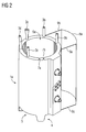
- FIG. 2 shows the electrical winding body 1a with feet 4 to form at least one gap 5 through which the air can be sucked in below the electrical winding body 1a.
- extension elements 3a, 3b, 3c, 3d, 3e are arranged on the upper end side of the electrical winding body 1a.
- the extension elements 3a, 3b, 3c, 3d, 3e are arranged on openings of continuous channels 10a, 10b (not shown) and lead to a forced cooling within the continuous cooling channel 10a, 10b by an increased discharge of the cooling medium.
- two openings 7a, 7b of the continuous channels 10a, 10b are shown.
- a side element 8a is arranged, wherein retaining elements 9a, 9b, 9c fix the side element to the outer surface of the electrical winding body 1a.
- the electric winding body 1a of the first phase has an extension member 2a with respect to the center passage opening 6a of the electrical winding body 1a.
- the channel 10a (not shown) of the central opening 6a is extended upward.
- the extension of the central opening 6a can also take place in the direction of the bottom, so that then an extended, beyond the outer dimensions of the electrical winding body 1a beyond continuous channel 10a is formed.
- the first electrical winding body 1a is partially enclosed by a side member 8a.
- the second electrical winding body 1b is not provided with any extension element. Rather, the middle electric winding body 1a has an air inlet 11 formed by the side members 8b, 8c through which the air is channeled to the electric winding body 1b and rises due to the heating inside the electrical winding body 1b.
- the right side side member 8c is directly connected to the adjoining side member 8d of the third electric winding body 1c.
- the side elements 8c, 8d are directly connected to each other and secured to a yoke, not shown.
- the third electrical winding body 1c has a plurality of extension elements 3a, 3b, 3c, 3d, 3e, which are arranged on the end face of the third electrical winding body 1c.
- the extension elements 3a, 3b, 3c, 3d, 3e can be selectively inserted into the openings 7a, 7b of the continuous channels 10a, 10b, so that not for each opening 7a, 7b, an extension element 3a, 3b, 3c, 3d, 3e due to thermal conditions within the cooling channel 10a, 10b is necessary.
- FIG. 4 shows a perspective view of the electrical winding body 1a with an extension element 2a within the central opening 6a.
- a side member 8a is attached, which leads to forced cooling of the outer surface of the electric winding body 1a due to the space thus formed.
- Due to the integration of feet 4 into the electrical winding body 1a a gap 5 is formed between the bottom of the electrical winding body 1a and the bottom.
- FIG. 5 An electrical winding body 1a is shown with an extension element 2a of the central opening 6a. Furthermore, at the indicated continuous cooling channels 10a, 10b at the openings 7a, 7b (not shown) in this respect extension elements 3a, 3b arranged. With the example shown the FIG. 5 on the one hand, a forced cooling within the central channel 10a and the opening 6a is given by the extension element 2a, so that a cooling of the innermost winding of the winding body 1a is ensured. Furthermore, the extension elements 3a, 3b of the continuous channels 10a, 10b support forced cooling in a central winding region, so that a uniform cooling of the electrical winding body 1a is ensured.
- FIG. 6 shows a perspective view of the transformer 15 according to the invention with three extension elements 2a, 2b, 2c, which are recessed with respect to the yoke 14.
- a separating element 13 according to the invention is mounted, which consists of two back-connected side elements 8b, 8c.
- the separating element 13 is connected to the yoke 14.
- the outer side members 8a, 8d also contribute to improved cooling of the transformer 15.
- the extension elements 2a, 2b, 2c go beyond the yoke 14 and are recessed with respect to the yoke 14. As a result, a subsequent attachment of the extension elements 2a, 2b, 2c is possible.
- the extension elements 2a, 2b, 2c may consist of composable segments which allow a single front and rear mounting of the segments of the extension elements 2a, 2b, 2c and then securely surrounding the yoke 14 by means of a suitable attachment.
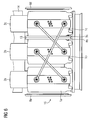
- FIG. 7 is a plan view of the separating element 13 is shown.
- Two differently shaped side elements 8a, 8b are connected to one another by means of a screw connection as a fastening element 12.
- a screw connection as a fastening element 12.
- one of the side elements 8b can be changed by the predetermined length of the screw 12, the shape of the side elements 8a, 8b targeted.
- the shape of the side elements 8a, 8b of the separating element 13 due to several fastening elements 12 is the top view FIG. 8 refer to.
- the shape of the side elements 8a, 8b and thus of the separating element 13 can be specified by the length adjustment of the fasteners 12, for example a screw.
Landscapes
- Engineering & Computer Science (AREA)
- Power Engineering (AREA)
- Coils Of Transformers For General Uses (AREA)
- Transformer Cooling (AREA)
Claims (17)
- Transformateur (15) ayant au moins un noyau magnétisable ayant une culasse (14) ayant au moins deux branches, ainsi qu'au moins deux corps (1a, 1b, 1c) d'enroulement électriques à refroidissement par de l'air ayant respectivement un enroulement conducteur de l'électricité et un isolant entourant l'enroulement respectif, l'isolant entourant entourant l'enroulement respectif et formant respectivement un corps d'enroulement stable mécaniquement et un corps (1a, 1b, 1c) d'enroulement électrique étant disposé sur une branche, au moins un élément (13) de séparation étant disposé entre deux corps (1a, 1b, 1c) d'enroulement électriques,
caractérisé en ce que
l'élément (13) de séparation est constitué d'au moins deux éléments (8a, 8b, 8c, 8d) latéraux pouvant être immobilisés l'un avec l'autre du côté arrière. - Transformateur (15) suivant la revendication 1,
caractérisé en ce que
les éléments (8a, 8b, 8c, 8d) latéraux de l'élément (13) de séparation peuvent être immobilisés sur la paroi arrière à l'aide d'au moins un élément (12) de fixation, l'application de force de l'élément (12) de fixation aux éléments (8a, 8b, 8c, 8d) latéraux influençant la forme des éléments (8a, 8b, 8c, 8d) latéraux. - Transformateur (15) suivant la revendication 1 ou 2,
caractérisé en ce que
les éléments (8a, 8b, 8c, 8d) latéraux de l'élément (13) de séparation sont conformés, en étant notamment ondulés, de manière à ce que, lorsque l'élément (12) de fixation applique une force, la forme des éléments (8a, 8b, 8c, 8d) peut être modifiée. - Transformateur (15) suivant l'une des revendications 1 à 3,
caractérisé en ce que
les éléments (8a, 8b, 8c, 8d) latéraux de l'élément (13) de séparation sont en un matériau élastique. - Transformateur (15) suivant l'une des revendications 1 à 4,
caractérisé en ce que
les éléments (8a, 8b, 8c, 8d) latéraux de l'élément (13) de séparation ont des points de fixation différents, de manière à ce que, lorsque plusieurs éléments (12) de fixation appliquent une force aux éléments (8a, 8b, 8c, 8d) latéraux, la forme des éléments (8a, 8b, 8c, 8d) latéraux puisse être modifiée. - Transformateur (15) suivant l'une des revendications 1 à 5,
caractérisé en ce que
le transformateur (15) est un transformateur à résine de coulée. - Transformateur (15) suivant l'une des revendications précédentes,
caractérisé en ce que
à l'intérieur d'au moins un corps (1a, 1b, 1c) d'enroulement électrique, est disposé au moins un canal (10a, 10b, 10c) traversant ayant une ouverture (6a, 7a, 7b) disposée sur la paroi extérieure du côté frontal du corps (1a, 1b, 1c) d'enroulement électrique, un élément (2a, 3a, 3b, 3c, 3d, 3e) de rallonge entourant directement l'ouverture (6a, 7a, 7b) et prolongeant le canal (10a, 10b, 10c) au-delà du corps (1a, 1b, 1c) d'enroulement électrique. - Transformateur (15) suivant la revendication 7,
caractérisé en ce que
l'élément (2a, 3a, 3b, 3c, 3d, 3e) de rallonge peut coulisser dans le canal (10a, 10b, 10c) traversant. - Transformateur (15) suivant l'une des revendications 7 ou 8,
caractérisé en ce que
l'élément (2a, 3a, 3b, 3c, 3d, 3e) de rallonge a une section transversale et/ou un diamètre différent rapporté à l'axe longitudinal de l'élément (2a, 3a, 3b, 3c, 3d, 3e) de rallonge. - Transformateur (15) suivant l'une des revendications 7 à 9,
caractérisé en ce que
l'élément (2a, 3a, 3b, 3c, 3d, 3e) de rallonge a, rapporté à l'axe longitudinal de l'élément (2a, 3a, 3b, 3c, 3d, 3e) de rallonge, une inclinaison, au moins en partie, et/ou un évidement, notamment par rapport à une culasse (14) supérieure. - Transformateur (15) suivant l'une des revendications 7 à 10,
caractérisé en ce que
l'élément (2a, 3a, 3b, 3c, 3d, 3e) de rallonge est, rapporté à l'axe longitudinal du corps (1a, 1b, 1c) d'enroulement, disposé sur au moins l'un des côtés frontaux du corps (1a, 1b, 1c) d'enroulement électrique. - Transformateur (15) suivant l'une des revendications 7 à 11,
caractérisé en ce que
l'élément (2a, 3a, 3b, 3c, 3d, 3e) de rallonge peut, au moyen d'éléments de fixation, être immobilisé sur et/ou à proximité immédiate de l'ouverture (6a, 7a, 7b). - Transformateur (15) suivant l'une des revendications 7 à 12,
caractérisé en ce que
un élément (8a, 8b, 8c, 8d) latéral peut, rapporté à l'axe longitudinal du corps (1a, 1b, 1c) d'enroulement, être disposé radialement sur le corps (1a, 1b, 1c) d'enroulement électrique et un canal traversant supplémentaire peut être produit par l'espace intermédiaire ainsi ménagé entre la surface extérieure du corps (1a, 1b, 1c) d'enroulement électrique et l'élément (8a, 8b, 8c, 8d) latéral. - Transformateur (15) suivant l'une des revendications 7 à 13,
caractérisé en ce que
l'élément (8a, 8b, 8c, 8d) latéral est conformé de manière à pouvoir, par une entrée (11) d'air, transporter un fluide de refroidissement extérieur au corps (1a, 1b, 1c) d'enroulement électrique et, par une distance à cet effet assez petite, entre l'élément (8a, 8b, 8c, 8d) et la paroi extérieure du corps (1a, 1b, 1c) d'enroulement électrique, il se crée une convexion renforcée du fluide de refroidissement. - Transformateur (15) suivant la revendication 14,
caractérisé en ce que
l'entrée (11) d'air est dirigée dans la direction d'un courant d'air extérieur renforcé du fluide de refroidissement. - Transformateur (15) suivant l'une des revendications 13 à 15,
caractérisé en ce que
l'élément (8a, 8b, 8c, 8d) latéral est, à l'aide d'un élément (9a, 9b, 9c, 9d) de maintien, mis sur la paroi extérieure du corps (1a, 1b, 1c) d'enroulement électrique. - Transformateur (15) suivant l'une des revendications 7 à 16,
caractérisé en ce que
l'élément (2a, 3a, 3b, 3c, 3d, 3e) de rallonge et/ou l'élément (8a, 8b, 8c, 8d) latéral comprend, au moins en partie, une matière plastique.
Applications Claiming Priority (1)
| Application Number | Priority Date | Filing Date | Title |
|---|---|---|---|
| PCT/EP2007/008631 WO2009046733A1 (fr) | 2007-09-28 | 2007-09-28 | Corps d'enroulement électrique et transformateur à refroidissement forcé |
Publications (2)
| Publication Number | Publication Date |
|---|---|
| EP2193530A1 EP2193530A1 (fr) | 2010-06-09 |
| EP2193530B1 true EP2193530B1 (fr) | 2016-09-14 |
Family
ID=39473379
Family Applications (1)
| Application Number | Title | Priority Date | Filing Date |
|---|---|---|---|
| EP07818709.3A Not-in-force EP2193530B1 (fr) | 2007-09-28 | 2007-09-28 | Corps d'enroulement électrique et transformateur à refroidissement forcé |
Country Status (7)
| Country | Link |
|---|---|
| US (1) | US8274350B2 (fr) |
| EP (1) | EP2193530B1 (fr) |
| CN (1) | CN101809686B (fr) |
| BR (1) | BRPI0722111B1 (fr) |
| CA (1) | CA2700669C (fr) |
| MX (1) | MX2010003420A (fr) |
| WO (1) | WO2009046733A1 (fr) |
Families Citing this family (9)
| Publication number | Priority date | Publication date | Assignee | Title |
|---|---|---|---|---|
| DE102011011302B4 (de) * | 2011-02-15 | 2024-11-14 | Sew-Eurodrive Gmbh & Co Kg | Anordnung zum Kühlen einer Spule und Umrichter |
| CN103988268A (zh) * | 2011-10-28 | 2014-08-13 | Abb技术有限公司 | 用于具有非直线芯部的变压器的整体模具 |
| DE102012208545A1 (de) | 2012-05-22 | 2013-11-28 | Schmidbauer Transformatoren und Gerätebau GmbH | Wassergekühlte elektrische Spule |
| PL2866235T3 (pl) * | 2013-10-22 | 2020-04-30 | Abb Schweiz Ag | Transformator wysokiego napięcia |
| DE102014015564A1 (de) | 2014-10-20 | 2016-04-21 | Dynamic E Flow Gmbh | Elektrische Kapillarleitereinheit |
| EP3147915A1 (fr) * | 2015-09-28 | 2017-03-29 | Siemens Aktiengesellschaft | Refroidissement d'un dispositif d'etranglement |
| WO2018231836A1 (fr) * | 2017-06-13 | 2018-12-20 | Radyne Corporation | Ensemble autotransformateur toroïdal portatif |
| DE102017220782A1 (de) * | 2017-11-21 | 2019-05-23 | Siemens Aktiengesellschaft | Transformator zur Befestigung an einem Mast eines Energieverteilungsnetzes |
| US10826297B2 (en) * | 2018-11-06 | 2020-11-03 | General Electric Company | System and method for wind power generation and transmission in electrical power systems |
Citations (4)
| Publication number | Priority date | Publication date | Assignee | Title |
|---|---|---|---|---|
| DE1980288U (de) * | 1966-07-26 | 1968-03-07 | Licentia Gmbh | In giessharz vergossene wicklung von transformatoren und drosselspulen. |
| US3548355A (en) * | 1969-04-10 | 1970-12-15 | Westinghouse Electric Corp | Foil coils with metallic back plates |
| EP1060484A1 (fr) * | 1998-12-29 | 2000-12-20 | Square D Company | Procede et appareil de refroidissement de transformateur |
| EP1282142A2 (fr) * | 2001-07-30 | 2003-02-05 | Siemens Aktiengesellschaft | Système d'enroulement électrique |
Family Cites Families (8)
| Publication number | Priority date | Publication date | Assignee | Title |
|---|---|---|---|---|
| GB671287A (en) * | 1949-12-12 | 1952-04-30 | Giuseppe Scarpa | Winding section for high-voltage transformers |
| DE1056730B (de) * | 1957-06-14 | 1959-05-06 | Licentia Gmbh | Anordnung zur raeumlichen Festlegung von Isolierbarrieren in fluessigkeits-gefuellten Transformatoren, Wandlern, Drosselspulen u. dgl. |
| US4173747A (en) * | 1978-06-08 | 1979-11-06 | Westinghouse Electric Corp. | Insulation structures for electrical inductive apparatus |
| SE9704415D0 (sv) * | 1997-02-03 | 1997-11-28 | Asea Brown Boveri | Horisontell luftkylning i en transformator |
| US6262503B1 (en) * | 1998-10-15 | 2001-07-17 | Massachusetts Institute Of Technology | Method and apparatus for cooling current carrying coil |
| US6924723B1 (en) * | 2000-04-28 | 2005-08-02 | Emf Therapeutics, Inc. | Cooling system for magnetic field generating device |
| US7129808B2 (en) * | 2004-09-01 | 2006-10-31 | Rockwell Automation Technologies, Inc. | Core cooling for electrical components |
| CN1873855A (zh) * | 2006-06-12 | 2006-12-06 | 张长增 | 变压器/电抗器导流散热/消音结构 |
-
2007
- 2007-09-28 US US12/680,337 patent/US8274350B2/en not_active Expired - Fee Related
- 2007-09-28 CA CA2700669A patent/CA2700669C/fr not_active Expired - Fee Related
- 2007-09-28 MX MX2010003420A patent/MX2010003420A/es active IP Right Grant
- 2007-09-28 CN CN2007801008649A patent/CN101809686B/zh not_active Expired - Fee Related
- 2007-09-28 WO PCT/EP2007/008631 patent/WO2009046733A1/fr not_active Ceased
- 2007-09-28 EP EP07818709.3A patent/EP2193530B1/fr not_active Not-in-force
- 2007-09-28 BR BRPI0722111A patent/BRPI0722111B1/pt not_active IP Right Cessation
Patent Citations (4)
| Publication number | Priority date | Publication date | Assignee | Title |
|---|---|---|---|---|
| DE1980288U (de) * | 1966-07-26 | 1968-03-07 | Licentia Gmbh | In giessharz vergossene wicklung von transformatoren und drosselspulen. |
| US3548355A (en) * | 1969-04-10 | 1970-12-15 | Westinghouse Electric Corp | Foil coils with metallic back plates |
| EP1060484A1 (fr) * | 1998-12-29 | 2000-12-20 | Square D Company | Procede et appareil de refroidissement de transformateur |
| EP1282142A2 (fr) * | 2001-07-30 | 2003-02-05 | Siemens Aktiengesellschaft | Système d'enroulement électrique |
Also Published As
| Publication number | Publication date |
|---|---|
| CN101809686A (zh) | 2010-08-18 |
| CN101809686B (zh) | 2012-11-14 |
| US20110175696A1 (en) | 2011-07-21 |
| BRPI0722111B1 (pt) | 2018-11-21 |
| CA2700669C (fr) | 2016-08-30 |
| BRPI0722111A2 (pt) | 2014-04-08 |
| US8274350B2 (en) | 2012-09-25 |
| MX2010003420A (es) | 2010-04-21 |
| WO2009046733A1 (fr) | 2009-04-16 |
| EP2193530A1 (fr) | 2010-06-09 |
| CA2700669A1 (fr) | 2009-04-16 |
Similar Documents
| Publication | Publication Date | Title |
|---|---|---|
| EP2193530B1 (fr) | Corps d'enroulement électrique et transformateur à refroidissement forcé | |
| EP1774544B1 (fr) | Support pour inductance et composant inductif comprenant ce support | |
| DE202009000990U1 (de) | Induktionsspulenträgervorrichtung | |
| WO2015110136A1 (fr) | Antenne, en particulier antenne de téléphonie mobile | |
| DE29619504U1 (de) | Miniaturventilator zur Ausgabe von Luft in einer bestimmten Richtung | |
| EP2936655A2 (fr) | Stator embouti pourvu d'un support de tete de bobine | |
| EP2466222A1 (fr) | Dispositif de chauffage électrique | |
| DE102018105029A1 (de) | Drosselspule | |
| DE102017106104A1 (de) | Auszugsführung und Mikrowellengargerät oder industrieller Wärmeofen mit einer Auszugsführung | |
| DE4333158A1 (de) | Gerät zum Zubereiten von Speisen | |
| DE202009000991U1 (de) | Kochfeld mit einem Montagerahmen und einem Metallträger | |
| DE4241025A1 (de) | Dielektrischer Resonator | |
| DE60306991T2 (de) | Befestigungsvorrichtung für Ringkerndrossel | |
| EP2442321B1 (fr) | Douille de traversée pour lignes de haute tension dans des transformateurs d'huile | |
| WO2017036438A1 (fr) | Four à creusets à induction et culasse magnétique associée | |
| EP2442319B1 (fr) | Douille de traversée pour lignes de haute tension dans des transformateurs d'huile | |
| EP2721620B1 (fr) | Ensemble d'enroulement comprenant un enroulement de bobine et un système de canaux de refroidissement | |
| DE102006001151B3 (de) | Heizerfeld eines Strahlungsheizers mit einer Heizspirale | |
| EP0289707B1 (fr) | Elément chauffant électrique avec prise | |
| DE19515308C1 (de) | Hochspannungs-Rohrgasleiter | |
| DE10120528B4 (de) | Bestückpfeiler und Deckbefestigung für einen solchen | |
| DE60222526T2 (de) | LC-Filtermodul und Wendelleiterfilter mit mindestens zwei solchen Modulen | |
| EP0563448B1 (fr) | Elément de radiation | |
| DE2726905B2 (de) | Einrichtung zum Beheizen eines Viehselbsttränkebeckens | |
| DE3113322C2 (de) | Verschlußdeckel an einem Flächenstrahler für Hochdruckentladungslampen |
Legal Events
| Date | Code | Title | Description |
|---|---|---|---|
| PUAI | Public reference made under article 153(3) epc to a published international application that has entered the european phase |
Free format text: ORIGINAL CODE: 0009012 |
|
| 17P | Request for examination filed |
Effective date: 20100312 |
|
| AK | Designated contracting states |
Kind code of ref document: A1 Designated state(s): AT BE BG CH CY CZ DE DK EE ES FI FR GB GR HU IE IS IT LI LT LU LV MC MT NL PL PT RO SE SI SK TR |
|
| AX | Request for extension of the european patent |
Extension state: AL BA HR MK RS |
|
| DAX | Request for extension of the european patent (deleted) | ||
| RAP1 | Party data changed (applicant data changed or rights of an application transferred) |
Owner name: SIEMENS AKTIENGESELLSCHAFT |
|
| 17Q | First examination report despatched |
Effective date: 20150601 |
|
| GRAP | Despatch of communication of intention to grant a patent |
Free format text: ORIGINAL CODE: EPIDOSNIGR1 |
|
| INTG | Intention to grant announced |
Effective date: 20160418 |
|
| GRAS | Grant fee paid |
Free format text: ORIGINAL CODE: EPIDOSNIGR3 |
|
| GRAA | (expected) grant |
Free format text: ORIGINAL CODE: 0009210 |
|
| AK | Designated contracting states |
Kind code of ref document: B1 Designated state(s): AT BE BG CH CY CZ DE DK EE ES FI FR GB GR HU IE IS IT LI LT LU LV MC MT NL PL PT RO SE SI SK TR |
|
| REG | Reference to a national code |
Ref country code: GB Ref legal event code: FG4D Free format text: NOT ENGLISH Ref country code: FR Ref legal event code: PLFP Year of fee payment: 10 |
|
| REG | Reference to a national code |
Ref country code: CH Ref legal event code: EP |
|
| REG | Reference to a national code |
Ref country code: IE Ref legal event code: FG4D Free format text: LANGUAGE OF EP DOCUMENT: GERMAN |
|
| REG | Reference to a national code |
Ref country code: AT Ref legal event code: REF Ref document number: 829787 Country of ref document: AT Kind code of ref document: T Effective date: 20161015 |
|
| REG | Reference to a national code |
Ref country code: DE Ref legal event code: R096 Ref document number: 502007015112 Country of ref document: DE |
|
| REG | Reference to a national code |
Ref country code: LT Ref legal event code: MG4D |
|
| REG | Reference to a national code |
Ref country code: NL Ref legal event code: MP Effective date: 20160914 |
|
| PG25 | Lapsed in a contracting state [announced via postgrant information from national office to epo] |
Ref country code: LT Free format text: LAPSE BECAUSE OF FAILURE TO SUBMIT A TRANSLATION OF THE DESCRIPTION OR TO PAY THE FEE WITHIN THE PRESCRIBED TIME-LIMIT Effective date: 20160914 Ref country code: FI Free format text: LAPSE BECAUSE OF FAILURE TO SUBMIT A TRANSLATION OF THE DESCRIPTION OR TO PAY THE FEE WITHIN THE PRESCRIBED TIME-LIMIT Effective date: 20160914 |
|
| PG25 | Lapsed in a contracting state [announced via postgrant information from national office to epo] |
Ref country code: SE Free format text: LAPSE BECAUSE OF FAILURE TO SUBMIT A TRANSLATION OF THE DESCRIPTION OR TO PAY THE FEE WITHIN THE PRESCRIBED TIME-LIMIT Effective date: 20160914 Ref country code: ES Free format text: LAPSE BECAUSE OF FAILURE TO SUBMIT A TRANSLATION OF THE DESCRIPTION OR TO PAY THE FEE WITHIN THE PRESCRIBED TIME-LIMIT Effective date: 20160914 Ref country code: BE Free format text: LAPSE BECAUSE OF NON-PAYMENT OF DUE FEES Effective date: 20160930 Ref country code: NL Free format text: LAPSE BECAUSE OF FAILURE TO SUBMIT A TRANSLATION OF THE DESCRIPTION OR TO PAY THE FEE WITHIN THE PRESCRIBED TIME-LIMIT Effective date: 20160914 Ref country code: GR Free format text: LAPSE BECAUSE OF FAILURE TO SUBMIT A TRANSLATION OF THE DESCRIPTION OR TO PAY THE FEE WITHIN THE PRESCRIBED TIME-LIMIT Effective date: 20161215 Ref country code: LV Free format text: LAPSE BECAUSE OF FAILURE TO SUBMIT A TRANSLATION OF THE DESCRIPTION OR TO PAY THE FEE WITHIN THE PRESCRIBED TIME-LIMIT Effective date: 20160914 |
|
| PG25 | Lapsed in a contracting state [announced via postgrant information from national office to epo] |
Ref country code: RO Free format text: LAPSE BECAUSE OF FAILURE TO SUBMIT A TRANSLATION OF THE DESCRIPTION OR TO PAY THE FEE WITHIN THE PRESCRIBED TIME-LIMIT Effective date: 20160914 Ref country code: EE Free format text: LAPSE BECAUSE OF FAILURE TO SUBMIT A TRANSLATION OF THE DESCRIPTION OR TO PAY THE FEE WITHIN THE PRESCRIBED TIME-LIMIT Effective date: 20160914 |
|
| REG | Reference to a national code |
Ref country code: CH Ref legal event code: PL |
|
| PG25 | Lapsed in a contracting state [announced via postgrant information from national office to epo] |
Ref country code: PT Free format text: LAPSE BECAUSE OF FAILURE TO SUBMIT A TRANSLATION OF THE DESCRIPTION OR TO PAY THE FEE WITHIN THE PRESCRIBED TIME-LIMIT Effective date: 20170116 Ref country code: PL Free format text: LAPSE BECAUSE OF FAILURE TO SUBMIT A TRANSLATION OF THE DESCRIPTION OR TO PAY THE FEE WITHIN THE PRESCRIBED TIME-LIMIT Effective date: 20160914 Ref country code: CZ Free format text: LAPSE BECAUSE OF FAILURE TO SUBMIT A TRANSLATION OF THE DESCRIPTION OR TO PAY THE FEE WITHIN THE PRESCRIBED TIME-LIMIT Effective date: 20160914 Ref country code: SK Free format text: LAPSE BECAUSE OF FAILURE TO SUBMIT A TRANSLATION OF THE DESCRIPTION OR TO PAY THE FEE WITHIN THE PRESCRIBED TIME-LIMIT Effective date: 20160914 Ref country code: BG Free format text: LAPSE BECAUSE OF FAILURE TO SUBMIT A TRANSLATION OF THE DESCRIPTION OR TO PAY THE FEE WITHIN THE PRESCRIBED TIME-LIMIT Effective date: 20161214 Ref country code: IS Free format text: LAPSE BECAUSE OF FAILURE TO SUBMIT A TRANSLATION OF THE DESCRIPTION OR TO PAY THE FEE WITHIN THE PRESCRIBED TIME-LIMIT Effective date: 20170114 |
|
| REG | Reference to a national code |
Ref country code: DE Ref legal event code: R097 Ref document number: 502007015112 Country of ref document: DE |
|
| REG | Reference to a national code |
Ref country code: IE Ref legal event code: MM4A |
|
| PG25 | Lapsed in a contracting state [announced via postgrant information from national office to epo] |
Ref country code: IT Free format text: LAPSE BECAUSE OF FAILURE TO SUBMIT A TRANSLATION OF THE DESCRIPTION OR TO PAY THE FEE WITHIN THE PRESCRIBED TIME-LIMIT Effective date: 20160914 |
|
| PLBE | No opposition filed within time limit |
Free format text: ORIGINAL CODE: 0009261 |
|
| STAA | Information on the status of an ep patent application or granted ep patent |
Free format text: STATUS: NO OPPOSITION FILED WITHIN TIME LIMIT |
|
| PG25 | Lapsed in a contracting state [announced via postgrant information from national office to epo] |
Ref country code: CH Free format text: LAPSE BECAUSE OF NON-PAYMENT OF DUE FEES Effective date: 20160930 Ref country code: DK Free format text: LAPSE BECAUSE OF FAILURE TO SUBMIT A TRANSLATION OF THE DESCRIPTION OR TO PAY THE FEE WITHIN THE PRESCRIBED TIME-LIMIT Effective date: 20160914 Ref country code: LI Free format text: LAPSE BECAUSE OF NON-PAYMENT OF DUE FEES Effective date: 20160930 Ref country code: IE Free format text: LAPSE BECAUSE OF NON-PAYMENT OF DUE FEES Effective date: 20160928 |
|
| 26N | No opposition filed |
Effective date: 20170615 |
|
| GBPC | Gb: european patent ceased through non-payment of renewal fee |
Effective date: 20161214 |
|
| PG25 | Lapsed in a contracting state [announced via postgrant information from national office to epo] |
Ref country code: LU Free format text: LAPSE BECAUSE OF NON-PAYMENT OF DUE FEES Effective date: 20160928 |
|
| REG | Reference to a national code |
Ref country code: FR Ref legal event code: PLFP Year of fee payment: 11 |
|
| REG | Reference to a national code |
Ref country code: AT Ref legal event code: MM01 Ref document number: 829787 Country of ref document: AT Kind code of ref document: T Effective date: 20160928 |
|
| REG | Reference to a national code |
Ref country code: BE Ref legal event code: MM Effective date: 20160930 |
|
| PG25 | Lapsed in a contracting state [announced via postgrant information from national office to epo] |
Ref country code: GB Free format text: LAPSE BECAUSE OF NON-PAYMENT OF DUE FEES Effective date: 20161214 Ref country code: SI Free format text: LAPSE BECAUSE OF FAILURE TO SUBMIT A TRANSLATION OF THE DESCRIPTION OR TO PAY THE FEE WITHIN THE PRESCRIBED TIME-LIMIT Effective date: 20160914 |
|
| PG25 | Lapsed in a contracting state [announced via postgrant information from national office to epo] |
Ref country code: AT Free format text: LAPSE BECAUSE OF NON-PAYMENT OF DUE FEES Effective date: 20160928 |
|
| PG25 | Lapsed in a contracting state [announced via postgrant information from national office to epo] |
Ref country code: HU Free format text: LAPSE BECAUSE OF FAILURE TO SUBMIT A TRANSLATION OF THE DESCRIPTION OR TO PAY THE FEE WITHIN THE PRESCRIBED TIME-LIMIT; INVALID AB INITIO Effective date: 20070928 Ref country code: CY Free format text: LAPSE BECAUSE OF FAILURE TO SUBMIT A TRANSLATION OF THE DESCRIPTION OR TO PAY THE FEE WITHIN THE PRESCRIBED TIME-LIMIT Effective date: 20160914 |
|
| PG25 | Lapsed in a contracting state [announced via postgrant information from national office to epo] |
Ref country code: MC Free format text: LAPSE BECAUSE OF FAILURE TO SUBMIT A TRANSLATION OF THE DESCRIPTION OR TO PAY THE FEE WITHIN THE PRESCRIBED TIME-LIMIT Effective date: 20160914 Ref country code: TR Free format text: LAPSE BECAUSE OF FAILURE TO SUBMIT A TRANSLATION OF THE DESCRIPTION OR TO PAY THE FEE WITHIN THE PRESCRIBED TIME-LIMIT Effective date: 20160914 Ref country code: MT Free format text: LAPSE BECAUSE OF FAILURE TO SUBMIT A TRANSLATION OF THE DESCRIPTION OR TO PAY THE FEE WITHIN THE PRESCRIBED TIME-LIMIT Effective date: 20160914 |
|
| REG | Reference to a national code |
Ref country code: FR Ref legal event code: PLFP Year of fee payment: 12 |
|
| PGFP | Annual fee paid to national office [announced via postgrant information from national office to epo] |
Ref country code: FR Payment date: 20200921 Year of fee payment: 14 |
|
| REG | Reference to a national code |
Ref country code: DE Ref legal event code: R081 Ref document number: 502007015112 Country of ref document: DE Owner name: SIEMENS ENERGY GLOBAL GMBH & CO. KG, DE Free format text: FORMER OWNER: SIEMENS AKTIENGESELLSCHAFT, 80333 MUENCHEN, DE |
|
| PGFP | Annual fee paid to national office [announced via postgrant information from national office to epo] |
Ref country code: DE Payment date: 20201118 Year of fee payment: 14 |
|
| REG | Reference to a national code |
Ref country code: DE Ref legal event code: R119 Ref document number: 502007015112 Country of ref document: DE |
|
| PG25 | Lapsed in a contracting state [announced via postgrant information from national office to epo] |
Ref country code: FR Free format text: LAPSE BECAUSE OF NON-PAYMENT OF DUE FEES Effective date: 20210930 Ref country code: DE Free format text: LAPSE BECAUSE OF NON-PAYMENT OF DUE FEES Effective date: 20220401 |