EP2193611B1 - Verfahren zum senden und empfangen eines signals in einem mehrantennensystem mithilfe räumlicher vorkodierung, sendegerät und empfangsgerät dafür sowie entsprechende computerprogammprodukte - Google Patents
Verfahren zum senden und empfangen eines signals in einem mehrantennensystem mithilfe räumlicher vorkodierung, sendegerät und empfangsgerät dafür sowie entsprechende computerprogammprodukte Download PDFInfo
- Publication number
- EP2193611B1 EP2193611B1 EP08838378A EP08838378A EP2193611B1 EP 2193611 B1 EP2193611 B1 EP 2193611B1 EP 08838378 A EP08838378 A EP 08838378A EP 08838378 A EP08838378 A EP 08838378A EP 2193611 B1 EP2193611 B1 EP 2193611B1
- Authority
- EP
- European Patent Office
- Prior art keywords
- antennas
- sending
- receiver
- transmission channel
- signal
- Prior art date
- Legal status (The legal status is an assumption and is not a legal conclusion. Google has not performed a legal analysis and makes no representation as to the accuracy of the status listed.)
- Active
Links
Images


Classifications
-
- H—ELECTRICITY
- H04—ELECTRIC COMMUNICATION TECHNIQUE
- H04B—TRANSMISSION
- H04B7/00—Radio transmission systems, i.e. using radiation field
- H04B7/02—Diversity systems; Multi-antenna system, i.e. transmission or reception using multiple antennas
- H04B7/04—Diversity systems; Multi-antenna system, i.e. transmission or reception using multiple antennas using two or more spaced independent antennas
- H04B7/0413—MIMO systems
- H04B7/0426—Power distribution
-
- H—ELECTRICITY
- H04—ELECTRIC COMMUNICATION TECHNIQUE
- H04B—TRANSMISSION
- H04B7/00—Radio transmission systems, i.e. using radiation field
- H04B7/02—Diversity systems; Multi-antenna system, i.e. transmission or reception using multiple antennas
- H04B7/04—Diversity systems; Multi-antenna system, i.e. transmission or reception using multiple antennas using two or more spaced independent antennas
- H04B7/0413—MIMO systems
- H04B7/0417—Feedback systems
-
- H—ELECTRICITY
- H04—ELECTRIC COMMUNICATION TECHNIQUE
- H04B—TRANSMISSION
- H04B7/00—Radio transmission systems, i.e. using radiation field
- H04B7/02—Diversity systems; Multi-antenna system, i.e. transmission or reception using multiple antennas
- H04B7/04—Diversity systems; Multi-antenna system, i.e. transmission or reception using multiple antennas using two or more spaced independent antennas
- H04B7/0413—MIMO systems
- H04B7/0456—Selection of precoding matrices or codebooks, e.g. using matrices antenna weighting
- H04B7/046—Selection of precoding matrices or codebooks, e.g. using matrices antenna weighting taking physical layer constraints into account
- H04B7/0465—Selection of precoding matrices or codebooks, e.g. using matrices antenna weighting taking physical layer constraints into account taking power constraints at power amplifier or emission constraints, e.g. constant modulus, into account
-
- Y—GENERAL TAGGING OF NEW TECHNOLOGICAL DEVELOPMENTS; GENERAL TAGGING OF CROSS-SECTIONAL TECHNOLOGIES SPANNING OVER SEVERAL SECTIONS OF THE IPC; TECHNICAL SUBJECTS COVERED BY FORMER USPC CROSS-REFERENCE ART COLLECTIONS [XRACs] AND DIGESTS
- Y02—TECHNOLOGIES OR APPLICATIONS FOR MITIGATION OR ADAPTATION AGAINST CLIMATE CHANGE
- Y02D—CLIMATE CHANGE MITIGATION TECHNOLOGIES IN INFORMATION AND COMMUNICATION TECHNOLOGIES [ICT], I.E. INFORMATION AND COMMUNICATION TECHNOLOGIES AIMING AT THE REDUCTION OF THEIR OWN ENERGY USE
- Y02D30/00—Reducing energy consumption in communication networks
- Y02D30/70—Reducing energy consumption in communication networks in wireless communication networks
Definitions
- the field of the invention is that of digital communications. More specifically, the invention relates to the transmission and reception of signals in the context of multiple-input multiple-output (MIMO) type multi-antenna systems ("Multiple Multiple Input Multiple Output").
- MIMO multiple-input multiple-output
- the invention finds particular applications in the field of radiocommunications, in systems having frequency selective transmission channels (single-carrier type systems) or non-frequency selective systems (multi-carrier type systems, for example OFDM type, in English " Orthogonal Frequency Division Multiplexing ").
- the invention is at the level of the physical layer of multi-antenna mobile access networks, and can be applied to uplink communications (from a terminal to a base station), as well as to downlink communications (from a base station to a terminal).
- Techniques for transmitting / receiving digital signals in multi-antenna systems have many advantages, especially for mobile access networks.
- such techniques allow an increase of the bit rates and / or the reliability of the transmissions in the context of wireless communications.
- a transmission technique is well suited to MIMO systems in which the transmission channel varies.
- This technique also called link adaptation, consists in adapting the resources used for transmission according to information representative of the transmission channel.
- This technique therefore requires a return path (also called “feedback") between the receiver and the transmitter, providing the transmitter with (usually partial) knowledge of the transmission channel.
- this link adaptation can be dynamic, and make it possible to adapt to instantaneous variations of the transmission channel, by seeking to maximize the bit rate of the radio link while respecting a certain quality of service, such as for example a transmission rate. maximum binary errors.
- the Modulation and Coding Scheme is modified for each transmitting antenna, that is to say for each data stream, and optionally the powers allocated to each data stream.
- MCS Modulation and Coding Scheme
- a receiver can determine the MCS (or discrete yields) per group of antennas to be used in transmission to minimize the difference with the theoretical performances, from the knowledge of a family of MCS diagrams available in transmission (according to the emission standard, for example), and transmit these elements to the transmitter in a return channel, for example in a CQI (Channel Quality Indicator) message.
- MCS Mobility Control Function
- the transmission system thus has an adaptive partition of a feedback information to another, in order to fight against quantization noise, or defined during the configuration of the system and fixed throughout the transmission.
- a disadvantage of this prior art technique is that it relies on the assumption of independent transmission of data streams by transmit antenna, i.e., the covariance matrix of the signal to transmit is of diagonal form, thus generating interference between the data streams.
- the invention proposes a new solution that does not have all of these disadvantages of the prior art, in the form of a method of transmitting a signal from a transmitter to a receiver via a transmission channel. in the form of a set of data streams between N T transmit antennas and N R receive antennas, with N T and N R greater than or equal to 2.
- the invention proposes to apply precoding to each group of transmit antennas.
- Such spatial precoding makes it possible in particular to transmit on the eigen modes of the transmission sub-channels. More specifically, a "subchannel" corresponds to the transmission channel between the transmitting antennas of a group considered, associated with a block of the precoding matrix, and the receiving antennas. The transmission channel between the transmitter and the receiver is thus partially decorrelated.
- the partition of the transmitting antennas into different groups that is to say the number of groups and the number of antennas composing each group, can be fixed (for example according to the application considered, or emission standard).
- the step of distributing the transmitting antennas makes it possible to determine which transmitting antenna is assigned to which group, according to the fixed partition.
- the antenna distribution step affects for example the antennas N Ti and N T2 to the group ⁇ 1 .
- This distribution step can be implemented periodically and / or as a function of a variation of the transmission channel.
- the antenna distribution step affects, for example, the antennas N T3 and N T5 to the group ⁇ 1 , the antennas N T1 and N T2 to the group ⁇ 2 , and the antenna N T4 to the group ⁇ 3 , based on information reported by the receiver relating to a variation of the transmission channel. If the transmission channel is invariant, the distribution of transmit antennas is not necessarily updated. On the other hand, an update may be necessary in case of modification of the powers and / or the efficiencies attributed to the transmitting antennas.
- the transmit antenna partition (i.e. the number of groups and the number of antennas per group) can also be adaptive, and modified periodically and / or according to a variation of the transmission channel.
- a performance is attributed to each of the transmission antennas, and a transmission power to each of the data streams. Yields are therefore not affected for each antenna group, but specifically for each transmitting antenna. It may be noted that such scalar encoding (i.e., along time dimension only) is easier to decode than a space-time encoding.
- the yields are selected from a predetermined set of discrete yields. This choice is a function of at least one constraint imposed by the receiver, such as the type of the receiver (for example of type with successive cancellations of interference).
- the predetermined set of returns is defined in a yield table, set by the standard. This set is also called MCS Modulation and Coding Scheme Set.
- precoding vectors forming the blocks of the precoding matrix can be defined in a precoding table, also called “codebook”, also defined in the standard.
- the precoding step comprises a substep of obtaining the eigenvectors associated with each of the blocks.
- the transmission powers of each data stream are determined, and the signal is transmitted on the non-zero eigenvalues of each of the sub-channels. It is recalled that a subchannel corresponding to the transmission channel between the transmitting antennas of a group, associated with a block of the precoding matrix, and the receiving antennas.
- This updating can be performed periodically, according to a variation of the transmission channel, according to a request from a user, depending on the modification of a transmission parameter, etc. It may be noted that these different elements can be updated even if the distribution of the transmit antennas has not been modified.
- the distribution in groups of transmitting antennas can be determined on the receiver side as a function of the information representative of the transmission channel, then transmitted to the transmitter, or else determined on the transmitter side, following the reception of the representative information of the transmission channel.
- the precoding matrix can be determined on the receiver side, and transmitted to the transmitter, or the precoding blocks or vectors forming the precoding matrix can be determined on the receiver side, and transmitted to the transmitter that determines the matrix. corresponding precoding, etc.
- Another embodiment of the invention relates to a transmitter adapted to transmit a signal to a receiver via a transmission channel, in the form of a set of data flows between N T transmit antennas and N R receiving antennas, with N T and N R greater than or equal to 2.
- Such an emitter is particularly suitable for implementing the transmission method described above.
- This is for example a base station, or a terminal type radiotelephone, laptop, personal assistant type PDA (in English "Personal Digital Assistant"), depending on whether one is link up or descending.
- Another aspect of the invention relates to a method of receiving a received signal, corresponding to a signal transmitted by a transmitter to a receiver via a transmission channel, in the form of a set of data streams between N T transmit antennas and N R receive antennas, with N T and N R greater than or equal to 2.
- the receiver determines the yields to be assigned to each transmitting antenna, the transmission powers associated with the data streams, as well as the corresponding spatial precoding matrix.
- the yields are selected from a predetermined set of discrete yields.
- the characteristics of the receiver and the transmission channel are taken into account in order to optimize the efficiencies attributed to each transmitting antenna, the transmission powers allocated to each data stream, as well as to distribute the data to be transmitted on the different antennas. emission, thanks to spatial precoding.
- the receiver is a receiver of successive interference cancellation type (SIC).
- SIC successive interference cancellation type
- a receiver adapted to receive a received signal, corresponding to a signal transmitted by a transmitter via a transmission channel, in the form of a set of data flows between N T antennas transmitters and N R receive antennas, with N T and N R greater than or equal to 2.
- Such a reception device is particularly suitable for implementing the reception method described above.
- This is for example a base station, or a terminal type radiotelephone, laptop, personal assistant type PDA (in English "Personal Digital Assistant"), depending on whether one is link up or descending.
- Another aspect of the invention relates to a transmission system consisting of a transmitter comprising N T transmit antennas and a receiver comprising N R receiving antennas, with N T and N R greater than or equal to 2.
- Such a system makes it possible to emit a signal in the form of a set of data flows between the N T transmit antennas and the N R receive antennas.
- the receiver is a receiver type interference cancellation successive (SIC).
- SIC receiver type interference cancellation successive
- Yet another aspect of the invention relates to a computer program product downloadable from a communication network and / or recorded on a computer-readable and / or executable medium by a processor, including program code instructions for the implementation of a computer program product. of the transmission method described above, and / or a computer program product downloadable from a communication network and / or recorded on a computer-readable and / or executable medium by a processor, comprising code instructions of program for carrying out the reception method described above.
- the general principle of the invention is based on the implementation of a transmission spatial precoding, in a multi-antenna system comprising at least two transmitting antennas N T ⁇ 2 and two receiving antennas N R ⁇ 2. reminds us that a spatial multiplexing of the data makes it possible to reach high spectral efficiencies.
- the transmission antennas are grouped by antenna group, as a function of at least one piece of information representative of the transmission channel between the transmitter and the receiver. There is therefore a return path between the receiver and the transmitter, providing the transmitter with partial knowledge of the transmission channel. This return path also makes it possible to adapt the distribution of the transmission antennas as a function of the variations of the transmission channel.
- the spatial precoding according to the invention then implements a block diagonal precoding matrix comprising at least two blocks, each block being associated with one of the groups of antennas.
- the present invention is based on the use of a precoding block per antenna group, the set of precoding blocks forming a precoding matrix.
- the covariance matrix of the transmitted signal, formed by the precoding matrix and the transmission powers, is therefore diagonal in block.
- the implementation of a spatial precoding in transmission makes it possible in particular to transmit on the eigen modes of the transmission sub-channels.
- the transmission channel is partially decorrelated, which limits the interference in reception.
- the blocks of the precoding matrix can be updated regularly, or as a function of variations in the transmission channel, or as a function of a change in a transmission parameter, etc. There is therefore a return path between the receiver and the transmitter (possibly separate from the return channel transmitting to the transmitter information for the distribution of transmission antennas in groups), making it possible to update the transmission parameters ( yields and / or power and / or precoding matrix).
- a specific efficiency is attributed to each of the transmit antennas, that is to say a scalar efficiency, and no longer a yield per antenna group.
- This characteristic has the effect of having a lower decoding complexity.
- the transmitting antennas are divided into several groups of antennas, at least one group comprising two antennas.
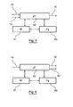
- This distribution 11 is performed taking into account at least one piece of information representative of the transmission channel. More specifically, the receiver can determine an optimal distribution according to the information representative of the transmission channel, and transmit (12) this distribution to the transmitter in a return channel, or transmit (12) directly the representative information from the transmission channel to the transmitter, which itself determines the optimal distribution.
- a performance (13) is then assigned to each of the transmit antennas and transmit power (14) to each of the data streams.
- the signal undergoes spatial precoding, implementing a block diagonal precoding matrix comprising at least two blocks, each block being associated with one of the antenna groups.
- the signal 16 thus precoded is then transmitted on the eigen modes of the transmission sub-channels, between each group of transmit antennas and the receiving antennas.
- the transmission antennas are divided into groups, and the transmitter implements a spatial precoding by group, thus reducing the load of the return channel.
- the transmitter is optimized by a joint processing between the precoding blocks associated with each of the transmit antenna groups, the transmit powers allocated on each data stream, and the selection of the returns for each transmit antenna (corresponding to a choice of MCS). This maximizes the spectral efficiency with regard in particular to the MCS that can be allocated to each non-zero eigenmode of the transmission sub-channels.
- the transmission is also constrained by supposing a type of reception with successive cancellations of interferences.
- the precoding blocks are constructed to be adapted to a SIC receiver.
- the nearest vector in the codebook (“codebook") is then selected. Reception is thus facilitated.
- This joint optimization under stress thus makes it possible to reduce the quantization noise, and thus to increase the transmission performance, especially in terms of spectral efficiency.
- the amount of information required transmitted on the return path depends on the chosen partition. This choice is in particular a function of the compromise performance / quantity of transported information wanted.
- the larger the number of groups the smaller the amount of information returned to the transmitter (in proportion to the size of the precoding blocks).
- the number of group K is strictly greater than 1 (that is to say that there are at least two groups of antennas), and strictly less than N T (which means that at least one groups includes two transmitting antennas).
- the signal received by the receiver on the N R receiving antennas is first processed to make an estimate of the transmission channel 32.
- This estimate 32 is taken into account for the determination and adaptation (31) of the returns , transmit powers and precoding blocks, as well as for decoding (33) the received signal or packet.
- the set of precoding blocks forms a precoding matrix adapted according to this particular embodiment to a simple SIC receiver, each block being associated with a separate group of transmitting antennas.
- V k the precoding block associated with the group k , with 1 ⁇ k ⁇ K.
- the emission powers are determined from applications of the Waterfilling algorithm (in French “waterfalls”). It is recalled that the Waterfilling type algorithm makes it possible to distribute the transmission power mainly on the strong eigen modes of the transmission channel, ie the channels experimenting with good radio conditions, while little or no power is allocated on the channels experiencing bad radio conditions.
- an iterative Waterfilling algorithm (in English "Iterative Waterfilling"), comprising Waterfilling operations, is thus applied to the system comprising K antenna groups.
- emission parameters efficiencies, transmission powers and precoding blocks
- the reporting of these transmission parameters can be done by separately assigning a CQI per antenna for the choice of a yield (MCS) or a power, and a CQI per group for the choice of the precoding block.
- MCS yield
- CQI per group for the choice of the precoding block.
- the return path therefore carries N T yield values to assign a yield to each transmit antenna, N T power values to assign a power to each data stream, and K precoding block values to assign a precoding block. to each group.
- a correspondence table of larger size is therefore necessarily stored during transmission and reception.
- a line of this correspondence table corresponds to the combination of N T MCS (each being chosen from the discrete yield table), of N T transmission powers, and K precoding blocks (each being chosen from the precoding table ).
- the joint enumeration according to this variant thus uses at most as many bits as the number of bits used for the signaling of the transmission parameters transmitting each information separately.
- the transmitter Upon receipt of the transmission parameters, the transmitter can allocate the efficiencies and the transmission powers, update the precoding matrix, and continue the transmission of the signal.
- the transmitting antennas are grouped in K groups, whose cardinality is between 1 and N R.
- the source data signal 10 at the input of the transmitter is first demultiplexed during a DEMUX 21 step, and converted into a number of independent flows corresponding to the number of non-zero eigenvalues of the sub-transmission channel.
- a scalar efficiency (MCS 13) and a transmission power (14) are then attributed to each of the independent streams, as a function of the information carried by the return channel 12 and extracted by the controller 22.
- Spatial precoding (15) is then implemented by means of a block diagonal precoding matrix composed of the blocks V 1 , V 2 , ..., V K. Precoding is therefore performed by antenna group.
- the following are the steps for determining the efficiencies, the powers, and the precoding blocks, making it possible to optimize the capacity of the transmission system.
- the quantization error relating to the precoding blocks is sufficiently small, and thus makes it possible to place in the optimum base of a Waterfilling per group.
- the precoding table codebook
- the precoding table comprises a sufficient number of precoding blocks, or precoding vectors for constructing the precoding blocks.
- the precoding blocks therefore correspond to the basis of a Waterfilling for each floor of the vector SIC (or equivalently, are the eigenvectors of B k in equation (5)).
- the architecture of the optimal receiver is thus reduced to a whitening filter followed by successive cancellations of interferences thanks to the consideration of this optimal basis.
- Annexes A, B and C describe algorithms for determining transmission parameters.
- the proposed algorithms leave a freedom in the scheduling of the different determination steps by means of the iteration indices M and N , with M and N being two positive integers. They are omitted for more than clarity in the description of the steps below.
- the quantization operation on the power requires rounding the result to the upper integer value, in order to be able to support the chosen MCS.
- Appendix A illustrates a first algorithm (algorithm 1) for determining the transmission parameters in a single-user system (or MIMO point-to-point) implementing a power constraint group.
- the algorithm 1 thus proposes to integrate at each iteration k with k ⁇ ⁇ 1, K ⁇ , that is to say for each group of antennas, quantization operations and redistribution of power.
- This algorithm is therefore based on iterative Waterfilling algorithm, which makes it possible to optimize the precoding blocks in transmission with a separate power constraint for each group.
- the proposed algorithm takes into account the discretization of the (yield and / or power) values during the optimization of the precoding blocks and makes the assumption a SIC receiver.
- Another difference lies in the fact that, in the single-user case, the power constraint to be respected is global: the power budget of the group k + 1 is thus increased with the remaining power of the group k .
- the power budget is distributed equally among all the groups so as not to favor or disadvantage one of the antenna groups.
- Appendix B illustrates a second algorithm (algorithm 2) for determining transmission parameters in a single-user system implementing a global power constraint.
- algorithm 2 takes into account a global power constraint.
- Step 2 is therefore based on an iterative Waterfilling type algorithm with a global power constraint (in English "sum power iterative Waterfilling").
- the proposed algorithm takes into account the discretization of the (yield and / or power) values during the optimization of the precoding blocks and makes the assumption of a SIC receiver.
- Appendix C illustrates a third algorithm (algorithm 3) for determining the transmission parameters in a single-user system, in which the receiver has an architecture of MMSE-SIC type (in English "minimum mean square error” for "minimizing the mean squared error”).
- a particular case of the invention is considered in which the quantization error on the precoding block V k is not negligible.
- the optimal receiver has an MMSE type architecture. -SIC, under the assumption of independent Gaussian entries.
- H ⁇ H ⁇ 1 ⁇ V ⁇ 1 ... H ⁇ k ⁇ V ⁇ K .
- algorithm 3 proposes an optimization of the transmission parameters taking into account a power constraint per antenna group. Again, it is also possible to optimize the transmission parameters taking into account a global power constraint, as proposed in algorithm 2.
- the powers are first fixed in a group thanks to the classic algorithm of Waterfilling.
- the covariance matrices are then generated with the eigenvectors of B k .
- the necessary power actually required is recalculated.
- the remaining power is then used to increase, if possible, one or more discrete yields. If there is still unused power, although insufficient to increase the sum-capacity, it is redistributed on the different antennas of the next group to reduce the bit error rate.
- An “uplink” configuration is considered representing the upstream link between the communication terminals (for example mobiles) and the base station. There is talk in this configuration of multiple access MIMO channel (in English “Multiple Access Channel (MAC)").
- the K users according to this configuration therefore correspond to the different communication terminals, and the receiver corresponds to the base station.
- MAC Multiple Access Channel
- the figure 4 illustrates more precisely a transmission scheme in this multi-user context MIMO MAC implementing K users.
- a group of antennas, and hence a precoding block is associated with each user U 1 ,..., U K.
- each user experiences a state of the channel noted H ⁇ 1 , ..., H ⁇ K , where H ⁇ i represents the state of the transmission channel for the user i.
- a transmitter according to this particular embodiment comprises a memory 51 constituted by a buffer memory, a processing unit 52, equipped for example with a microprocessor ⁇ P, and driven by the computer program 53, implementing the method transmission according to the invention.
- the code instructions of the computer program 53 are for example loaded into a RAM before being executed by the processor of the processing unit 52.
- the processing unit 52 receives as input a signal source data to be transmitted 10, as well as information from the receiver 12 (for example the transmission parameters or information making it possible to determine these transmission parameters, the distribution of the antennas or information representative of the transmission channel, etc. ).
- the microprocessor of the processing unit 52 implements the steps of the transmission method described above, according to the instructions of the computer program 53.
- the transmitter comprises, in addition to the buffer memory 51, distribution means transmission antennas in several antenna groups, means for allocating a return to each of the transmit antennas, means for allocating a power to each of the data streams, and precoding means spatial signal.
- the processing unit 52 therefore transmits to the receiver a precoded signal 16, transmitted according to the previously defined transmission parameters.
- a receiver As illustrated in figure 6 a receiver according to the embodiment described comprises a memory 61 consisting of a buffer memory, a processing unit 62, equipped for example with a microprocessor ⁇ P, and driven by the computer program 63, implementing the method reception according to the invention.
- the code instructions of the computer program 63 are for example loaded into a RAM memory before being executed by the processor of the processing unit 62.
- the processing unit 62 receives as input a received signal corresponding to the transmitted signal 16.
- the microprocessor of the processing unit 62 implements the steps of the reception method described above, according to the instructions of the computer program 63.
- the receiver comprises, in addition to the buffer memory 61, means for obtaining data. at least one distribution of the transmission antennas into several groups of antennas, means for determining a performance to be attributed to each of the transmit antennas, means for determining a transmission power to be allocated to each data streams, means for determining a diagonal precoding matrix per block, and means for transmitting to the transmitter the efficiencies, powers and precoding matrix thus determined.
- the processing unit 62 thus delivers the decoded data signal, or decoded packets 64, as well as transmission parameters to be transmitted to the transmitter in a return channel 12.
- such a receiver is of SIC type.
Landscapes
- Engineering & Computer Science (AREA)
- Computer Networks & Wireless Communication (AREA)
- Signal Processing (AREA)
- Power Engineering (AREA)
- Radio Transmission System (AREA)
- Mobile Radio Communication Systems (AREA)
- Radar Systems Or Details Thereof (AREA)
Claims (14)
- Verfahren zum Senden eines Signals von einem Sender zu einem Empfänger über einen Übertragungskanal in Form einer Datenflusseinheit zwischen NT Sendeantennen und NR Empfangsantennen, mit NT und NR höher als oder gleich 2,wobei das Verfahren einen Schritt der Verteilung der Sendeantennen auf mehrere Gruppen von mindestens einer Antenne enthält, wobei mindestens eine Gruppe zwei Antennen enthält, in Abhängigkeit von mindestens einer Information, die für den Übertragungskanal repräsentativ ist;dadurch gekennzeichnet, dass es ebenfalls enthält:- einen Schritt der Zuteilung eines Wirkungsgrade zu jeder der Sendeantennen;- einen Schritt der Zuweisung einer Sendeleistung zu jedem der Datenflüsse; und- einen Schritt der räumlichen Vorcodierung des Signals, der eine Diagonalmatrix zur blockweisen Vorcodierung verwendet, die mindestens zwei Blöcke enthält, wobei jeder Block einer der Antennengruppen zugeordnet ist.
- Sendeverfahren nach Anspruch 1, dadurch gekennzeichnet, dass die Wirkungsgrade in Abhängigkeit von mindestens einer vom Empfänger vorgegebenen Beschränkung unter einer vorbestimmten Einheit von diskreten Wirkungsgraden ausgewählt werden.
- Sendeverfahren nach einem der Ansprüche 1 und 2, dadurch gekennzeichnet, dass der Schritt der Vorcodierung einen Teilschritt des Erhalts der jedem der Blöcke zugeordneter Eigenvektoren enthält, um das Signal auf die Eigenwerte ungleich Null jedes der Teilkanäle zu übertragen,
wobei ein Teilkanal dem Übertragungskanal zwischen den Sendeantennen einer der Gruppen, die einem der Blöcke der Vorcodierungsmatrix zugeordnet ist, und den Empfangsantennen entspricht. - Sendeverfahren nach einem der Ansprüche 1 bis 3, dadurch gekennzeichnet, dass es einen Schritt der Aktualisierung mindestens eines Elements enthält, das zu der Gruppe gehört, die enthält:- mindestens einen der Blöcke;- mindestens einen der Wirkungsgrade;- mindestens eine der Sendeleistungen;- mindestens einen Vorcodiervektor, wobei jeder Block der Vorcodiermatrix mindestens einen Vorcodiervektor enthält;
in Abhängigkeit von einer Rückinformation des Empfängers. - Sendeverfahren nach einem der Ansprüche 1 bis 4, dadurch gekennzeichnet, dass es einen Schritt des Empfangs mindestens eines Elements enthält, das zu der Gruppe gehört, die enthält:- eine Information bezüglich der Verteilung der Sendeantennen in Gruppen;- die für den Übertragungskanal repräsentative Information;- die jeder der Sendeantennen zugeteilten Wirkungsgrade;- die Vorcodiermatrix;- die die Vorcodiermatrix bildenden Blöcke;- Vorcodiervektoren für den Aufbau der Vorcodiermatrix;- Werte der für jeden der Datenflüsse erforderlichen Sendeleistung für jede Gruppe von Sendeantennen oder für die Gesamtheit der Sendeantennen.
- Sendeverfahren nach einem der Ansprüche 1 bis 5, dadurch gekennzeichnet, dass der Schritt der Verteilung periodisch und/oder in Abhängigkeit von einer Veränderung des Übertragungskanals angewendet wird.
- Computerprogrammprodukt, das Programmcodeanweisungen enthält, die das Sendeverfahren nach Anspruch 1 verwenden, wenn es von einem Computer ausgeführt wird.
- Sender, der über einen Übertragungskanal ein Signal in Form einer Datenflusseinheit zwischen NT Sendeantennen und NR Empfangsantennen an einen Empfänger senden kann, mit NT und NR größer als oder gleich 2,wobei der Sender Einrichtungen zur Verteilung der Sendeantennen in mehrere Gruppen von mindestens einer Antenne enthält, wobei mindestens eine Gruppe zwei Antennen enthält, in Abhängigkeit von mindestens einer Information, die für den Übertragungskanal repräsentativ ist;
dadurch gekennzeichnet, dass er ebenfalls enthält:- Einrichtungen zur Zuteilung eines Wirkungsgrads zu jeder der Sendeantennen;- Einrichtungen zur Zuweisung einer Sendeleistung zu jedem der Datenflüsse;- Einrichtungen zur räumlichen Vorcodierung des Signals, die eine Diagonalmatrix zur blockweisen Vorcodierung verwenden, die mindestens zwei Blöcke enthält, wobei jeder Block einer der Antennengruppen zugeordnet ist. - Verfahren zum Empfang eines empfangenen Signals, das einem von einem Sender über einen Übertragungskanal an einen Empfänger gesendeten Signal in Form einer Datenflusseinheit zwischen NT Sendeantennen und NR Empfangsantennen entspricht, mit NT und NR größer als oder gleich 2,wobei das Verfahren einen Schritt des Erhalts, in Abhängigkeit von einer für den Übertragungskanal repräsentativen Information, mindestens einer Verteilung der Sendeantennen in mehrere Gruppen von mindestens einer Antenne enthält, wobei mindestens eine Gruppe zwei Antennen enthält;dadurch gekennzeichnet, dass es ebenfalls enthält:- einen Schritt der Bestimmung eines jeder der Sendeantennen zuzuteilenden Wirkungsgrads;- einen Schritt der Bestimmung einer jedem der Datenflüsse zuzuweisenden Sendeleistung;- einen Schritt der Bestimmung einer Diagonalmatrix zur blockweisen Vorcodierung, die mindestens zwei Blöcke enthält, wobei jeder Block einer der Antennengruppen zugeordnet ist; und- einen Schritt der Übertragung der Wirkungsgrade, der Sendeleistungen und der Vorcodiermatrix an den Sender.
- Empfangsverfahren nach Anspruch 9, dadurch gekennzeichnet, dass die Wirkungsgrade aus einer vorbestimmten Einheit von diskreten Wirkungsgraden ausgewählt werden.
- Empfangsverfahren nach einem der Ansprüche 9 und 10, dadurch gekennzeichnet, dass der Empfänger ein Empfänger mit aufeinanderfolgenden Interferenzaufhebungen ist.
- Computerprogrammprodukt, das Programmcodeanweisungen enthält, die das Empfangsverfahren nach Anspruch 9 verwenden, wenn es auf einem Computer ausgeführt wird.
- Empfänger, der ein empfangenes Signal empfangen kann, das einem Signal entspricht, welches von einem Sender über einen Übertragungskanal in Form einer Einheit von Datenflüssen zwischen NT Sendeantennen und NR Empfangsantennen gesendet wird, mit NT und NR höher als oder gleich 2,wobei der Empfänger Einrichtungen für den Erhalt, in Abhängigkeit von einer für den Übertragungskanal repräsentativen Information, von mindestens einer Verteilung der Sendeantennen in mehrere Gruppen von mindestens einer Antenne enthält, wobei mindestens eine Gruppe zwei Antennen enthält;dadurch gekennzeichnet, dass er ebenfalls enthält:- Einrichtungen zur Bestimmung eines jeder der Sendeantennen zuzuteilenden Wirkungsgrads;- Einrichtungen zur Bestimmung einer jedem der Datenflüsse zuzuweisenden Sendeleistung;- Einrichtungen zur Bestimmung einer Diagonalmatrix zur blockweisen Vorcodierung, die mindestens zwei Blöcke enthält, wobei jeder Block einer der Antennengruppen zugeordnet ist; und- Einrichtungen zur Übertragung der Wirkungsgrade, der Sendeleistungen und der Vorcodiermatrix an den Sender.
- Übertragungssystem, das von einem Sender, der NT Sendeantennen enthält, und von einem Empfänger, der NR Empfangsantennen enthält, gebildet wird, mit NT und NR größer als oder gleich 2,wobei der Sender über einen Übertragungskanal ein Signal in Form einer Datenflusseinheit zwischen den NT Sendeantennen und den NR Empfangsantennen an den Empfänger senden kann, wobei der Empfänger Einrichtungen für den Erhalt, in Abhängigkeit von einer für den Übertragungskanal repräsentativen Information, mindestens einer Verteilung der Sendeantennen in mehrere Gruppen von mindestens einer Antenne enthält, wobei mindestens eine Gruppe zwei Antennen enthält,wobei der Sender Einrichtungen zur Verteilung der Sendeantennen gemäß der Verteilung enthält; dadurch gekennzeichnet, dass der Empfänger ebenfalls enthält:- Einrichtungen zur Bestimmung eines jeder der Sendeantennen zuzuteilenden Wirkungsgrads;- Einrichtungen zur Bestimmung einer jedem der Datenflüsse zuzuweisenden Sendeleistung,- Einrichtungen zur Bestimmung einer Diagonalmatrix zur blockweisen Vorcodierung, die mindestens zwei Blöcke enthält, wobei jeder Block einer der Antennengruppen zugeordnet ist; und- Einrichtungen zur Übertragung der Wirkungsgrade, der Sendeleistungen und der Vorcodiermatrix an den Sender;und dass der Sender ebenfalls enthält:- Einrichtungen zur Zuteilung der Wirkungsgrade zu den Sendeantennen;- Einrichtungen zur Zuweisung der Sendeleistungen zu den Datenflüssen;- Einrichtungen zur räumlichen Vorcodierung des zu sendenden Signals, die die Vorcodiermatrix verwenden.
Applications Claiming Priority (2)
| Application Number | Priority Date | Filing Date | Title |
|---|---|---|---|
| FR0757727 | 2007-09-20 | ||
| PCT/FR2008/051581 WO2009047416A2 (fr) | 2007-09-20 | 2008-09-05 | Procede d'emission et de reception d'un signal dans un systeme multi-antennes mettant en oeuvre un precodage spatial, emetteur, recepteur, et produits programme d'ordinateur correspondants |
Publications (2)
| Publication Number | Publication Date |
|---|---|
| EP2193611A2 EP2193611A2 (de) | 2010-06-09 |
| EP2193611B1 true EP2193611B1 (de) | 2011-03-09 |
Family
ID=39326995
Family Applications (1)
| Application Number | Title | Priority Date | Filing Date |
|---|---|---|---|
| EP08838378A Active EP2193611B1 (de) | 2007-09-20 | 2008-09-05 | Verfahren zum senden und empfangen eines signals in einem mehrantennensystem mithilfe räumlicher vorkodierung, sendegerät und empfangsgerät dafür sowie entsprechende computerprogammprodukte |
Country Status (6)
| Country | Link |
|---|---|
| US (1) | US8422582B2 (de) |
| EP (1) | EP2193611B1 (de) |
| CN (1) | CN101861705B (de) |
| AT (1) | ATE501556T1 (de) |
| DE (1) | DE602008005479D1 (de) |
| WO (1) | WO2009047416A2 (de) |
Families Citing this family (3)
| Publication number | Priority date | Publication date | Assignee | Title |
|---|---|---|---|---|
| CN105337692B (zh) * | 2014-08-14 | 2019-09-17 | 电信科学技术研究院 | 下行信道预编码方法与装置 |
| CN105450343B (zh) * | 2014-08-30 | 2018-11-06 | 华为技术有限公司 | 一种预编码的方法、装置及系统 |
| CN105099621B (zh) * | 2015-06-29 | 2018-05-22 | 珠海市魅族科技有限公司 | 通信方法和通信设备 |
Family Cites Families (11)
| Publication number | Priority date | Publication date | Assignee | Title |
|---|---|---|---|---|
| EP1255369A1 (de) | 2001-05-04 | 2002-11-06 | TELEFONAKTIEBOLAGET LM ERICSSON (publ) | Verbindungsanpassung für drahtlose Kommunikationssysteme mit mehreren Eingängen und mehreren Ausgängen |
| US7181167B2 (en) | 2001-11-21 | 2007-02-20 | Texas Instruments Incorporated | High data rate closed loop MIMO scheme combining transmit diversity and data multiplexing |
| US8208364B2 (en) * | 2002-10-25 | 2012-06-26 | Qualcomm Incorporated | MIMO system with multiple spatial multiplexing modes |
| WO2006002550A1 (en) | 2004-07-07 | 2006-01-12 | Nortel Networks Limited | System and method for mapping symbols for mimo transmission |
| FI20041311A0 (fi) | 2004-10-08 | 2004-10-08 | Nokia Corp | Lohkomodulaatio |
| CN1838556A (zh) | 2005-03-24 | 2006-09-27 | 松下电器产业株式会社 | 一种下行多用户空时分组预编码的方法 |
| US7839842B2 (en) * | 2005-09-21 | 2010-11-23 | Broadcom Corporation | Method and system for a range reduction scheme for user selection in a multiuser MIMO downlink transmission |
| KR20080022033A (ko) * | 2006-09-05 | 2008-03-10 | 엘지전자 주식회사 | 프리코딩 정보 피드백 방법 및 프리코딩 방법 |
| KR20080026010A (ko) * | 2006-09-19 | 2008-03-24 | 엘지전자 주식회사 | 위상천이 기반의 프리코딩을 이용한 데이터 전송 방법 및이를 구현하는 송수신 장치 |
| US8102931B2 (en) * | 2006-09-29 | 2012-01-24 | Apple Inc. | Method and device for operating a precoded MIMO system |
| US7702029B2 (en) * | 2006-10-02 | 2010-04-20 | Freescale Semiconductor, Inc. | MIMO precoding enabling spatial multiplexing, power allocation and adaptive modulation and coding |
-
2008
- 2008-09-05 AT AT08838378T patent/ATE501556T1/de not_active IP Right Cessation
- 2008-09-05 DE DE602008005479T patent/DE602008005479D1/de active Active
- 2008-09-05 US US12/679,218 patent/US8422582B2/en active Active
- 2008-09-05 WO PCT/FR2008/051581 patent/WO2009047416A2/fr not_active Ceased
- 2008-09-05 EP EP08838378A patent/EP2193611B1/de active Active
- 2008-09-05 CN CN2008801166420A patent/CN101861705B/zh active Active
Also Published As
| Publication number | Publication date |
|---|---|
| CN101861705A (zh) | 2010-10-13 |
| WO2009047416A3 (fr) | 2009-08-20 |
| ATE501556T1 (de) | 2011-03-15 |
| DE602008005479D1 (de) | 2011-04-21 |
| US8422582B2 (en) | 2013-04-16 |
| EP2193611A2 (de) | 2010-06-09 |
| CN101861705B (zh) | 2013-05-15 |
| US20100309995A1 (en) | 2010-12-09 |
| WO2009047416A2 (fr) | 2009-04-16 |
Similar Documents
| Publication | Publication Date | Title |
|---|---|---|
| JP4105133B2 (ja) | 多重送受信アンテナを使用する移動通信システムで多重使用者のためのスケジューリング方法及び装置 | |
| Zhang et al. | Cross-layer-based modeling for quality of service guarantees in mobile wireless networks | |
| US8054837B2 (en) | Multiuser scheduling for MIMO broadcast channels with finite rate feedback | |
| JP5006393B2 (ja) | 閉ループ多重アンテナシステムにおけるデータ送受信装置及びその方法 | |
| US8265697B2 (en) | Restricted multi-rank precoding in multiple antenna systems | |
| US8571121B2 (en) | Method for SER approximation for OSTBC in distributed wire communication systems | |
| RU2527748C2 (ru) | Предварительное кодирование для зависящего от сегмента планирования в беспроводных системах связи | |
| US7961807B2 (en) | Reference signaling scheme using compressed feedforward codebooks for multi-user, multiple input, multiple output (MU-MIMO) systems | |
| Kountouris et al. | Enhanced multiuser random beamforming: Dealing with the not so large number of users case | |
| EP2062377B1 (de) | Adaptives verfahren zum senden und empfangen eines signals in einem mehrantennensystem, entsprechende sende- und empfangsgeräte, computerprogramm und signal | |
| EP2193611B1 (de) | Verfahren zum senden und empfangen eines signals in einem mehrantennensystem mithilfe räumlicher vorkodierung, sendegerät und empfangsgerät dafür sowie entsprechende computerprogammprodukte | |
| WO2024261039A1 (fr) | Procédé de communication mu-mimo distinguant entre données et symboles de référence pour l'allocation de puissance et dispositifs correspondant | |
| Caire et al. | Achievable rates of MIMO downlink beamforming with non-perfect CSI: a comparison between quantized and analog feedback | |
| CN103259587B (zh) | 一种用于MIMO通信系统的平均QoE最大化调度方法 | |
| KR20080068986A (ko) | 다중 안테나 시스템의 간섭 제거 장치 및 방법 | |
| FR3150374A1 (fr) | Procédé de communication SU-MIMO distinguant entre données et symboles de référence pour l’allocation de puissance et dispositifs correspondant | |
| EP4482243A1 (de) | Verfahren zur hybriden namens-/tdma-kommunikation für cluster-ad-hoc-netzwerke | |
| Nishimura et al. | Simplification of transmit resource control in E-SDM with adaptive modulation |
Legal Events
| Date | Code | Title | Description |
|---|---|---|---|
| PUAI | Public reference made under article 153(3) epc to a published international application that has entered the european phase |
Free format text: ORIGINAL CODE: 0009012 |
|
| 17P | Request for examination filed |
Effective date: 20100318 |
|
| AK | Designated contracting states |
Kind code of ref document: A2 Designated state(s): AT BE BG CH CY CZ DE DK EE ES FI FR GB GR HR HU IE IS IT LI LT LU LV MC MT NL NO PL PT RO SE SI SK TR |
|
| AX | Request for extension of the european patent |
Extension state: AL BA MK RS |
|
| GRAP | Despatch of communication of intention to grant a patent |
Free format text: ORIGINAL CODE: EPIDOSNIGR1 |
|
| GRAS | Grant fee paid |
Free format text: ORIGINAL CODE: EPIDOSNIGR3 |
|
| GRAA | (expected) grant |
Free format text: ORIGINAL CODE: 0009210 |
|
| AK | Designated contracting states |
Kind code of ref document: B1 Designated state(s): AT BE BG CH CY CZ DE DK EE ES FI FR GB GR HR HU IE IS IT LI LT LU LV MC MT NL NO PL PT RO SE SI SK TR |
|
| REG | Reference to a national code |
Ref country code: GB Ref legal event code: FG4D Free format text: NOT ENGLISH |
|
| REG | Reference to a national code |
Ref country code: CH Ref legal event code: EP |
|
| REG | Reference to a national code |
Ref country code: IE Ref legal event code: FG4D Free format text: LANGUAGE OF EP DOCUMENT: FRENCH |
|
| REF | Corresponds to: |
Ref document number: 602008005479 Country of ref document: DE Date of ref document: 20110421 Kind code of ref document: P |
|
| REG | Reference to a national code |
Ref country code: DE Ref legal event code: R096 Ref document number: 602008005479 Country of ref document: DE Effective date: 20110421 |
|
| REG | Reference to a national code |
Ref country code: NL Ref legal event code: VDEP Effective date: 20110309 |
|
| PG25 | Lapsed in a contracting state [announced via postgrant information from national office to epo] |
Ref country code: GR Free format text: LAPSE BECAUSE OF FAILURE TO SUBMIT A TRANSLATION OF THE DESCRIPTION OR TO PAY THE FEE WITHIN THE PRESCRIBED TIME-LIMIT Effective date: 20110610 Ref country code: ES Free format text: LAPSE BECAUSE OF FAILURE TO SUBMIT A TRANSLATION OF THE DESCRIPTION OR TO PAY THE FEE WITHIN THE PRESCRIBED TIME-LIMIT Effective date: 20110620 Ref country code: SE Free format text: LAPSE BECAUSE OF FAILURE TO SUBMIT A TRANSLATION OF THE DESCRIPTION OR TO PAY THE FEE WITHIN THE PRESCRIBED TIME-LIMIT Effective date: 20110309 Ref country code: LV Free format text: LAPSE BECAUSE OF FAILURE TO SUBMIT A TRANSLATION OF THE DESCRIPTION OR TO PAY THE FEE WITHIN THE PRESCRIBED TIME-LIMIT Effective date: 20110309 Ref country code: NO Free format text: LAPSE BECAUSE OF FAILURE TO SUBMIT A TRANSLATION OF THE DESCRIPTION OR TO PAY THE FEE WITHIN THE PRESCRIBED TIME-LIMIT Effective date: 20110609 Ref country code: LT Free format text: LAPSE BECAUSE OF FAILURE TO SUBMIT A TRANSLATION OF THE DESCRIPTION OR TO PAY THE FEE WITHIN THE PRESCRIBED TIME-LIMIT Effective date: 20110309 Ref country code: HR Free format text: LAPSE BECAUSE OF FAILURE TO SUBMIT A TRANSLATION OF THE DESCRIPTION OR TO PAY THE FEE WITHIN THE PRESCRIBED TIME-LIMIT Effective date: 20110309 |
|
| LTIE | Lt: invalidation of european patent or patent extension |
Effective date: 20110309 |
|
| PG25 | Lapsed in a contracting state [announced via postgrant information from national office to epo] |
Ref country code: BG Free format text: LAPSE BECAUSE OF FAILURE TO SUBMIT A TRANSLATION OF THE DESCRIPTION OR TO PAY THE FEE WITHIN THE PRESCRIBED TIME-LIMIT Effective date: 20110609 Ref country code: SI Free format text: LAPSE BECAUSE OF FAILURE TO SUBMIT A TRANSLATION OF THE DESCRIPTION OR TO PAY THE FEE WITHIN THE PRESCRIBED TIME-LIMIT Effective date: 20110309 Ref country code: NL Free format text: LAPSE BECAUSE OF FAILURE TO SUBMIT A TRANSLATION OF THE DESCRIPTION OR TO PAY THE FEE WITHIN THE PRESCRIBED TIME-LIMIT Effective date: 20110309 Ref country code: AT Free format text: LAPSE BECAUSE OF FAILURE TO SUBMIT A TRANSLATION OF THE DESCRIPTION OR TO PAY THE FEE WITHIN THE PRESCRIBED TIME-LIMIT Effective date: 20110309 Ref country code: CY Free format text: LAPSE BECAUSE OF FAILURE TO SUBMIT A TRANSLATION OF THE DESCRIPTION OR TO PAY THE FEE WITHIN THE PRESCRIBED TIME-LIMIT Effective date: 20110309 Ref country code: FI Free format text: LAPSE BECAUSE OF FAILURE TO SUBMIT A TRANSLATION OF THE DESCRIPTION OR TO PAY THE FEE WITHIN THE PRESCRIBED TIME-LIMIT Effective date: 20110309 |
|
| REG | Reference to a national code |
Ref country code: IE Ref legal event code: FD4D |
|
| PG25 | Lapsed in a contracting state [announced via postgrant information from national office to epo] |
Ref country code: PT Free format text: LAPSE BECAUSE OF FAILURE TO SUBMIT A TRANSLATION OF THE DESCRIPTION OR TO PAY THE FEE WITHIN THE PRESCRIBED TIME-LIMIT Effective date: 20110711 Ref country code: EE Free format text: LAPSE BECAUSE OF FAILURE TO SUBMIT A TRANSLATION OF THE DESCRIPTION OR TO PAY THE FEE WITHIN THE PRESCRIBED TIME-LIMIT Effective date: 20110309 Ref country code: IE Free format text: LAPSE BECAUSE OF FAILURE TO SUBMIT A TRANSLATION OF THE DESCRIPTION OR TO PAY THE FEE WITHIN THE PRESCRIBED TIME-LIMIT Effective date: 20110309 |
|
| PG25 | Lapsed in a contracting state [announced via postgrant information from national office to epo] |
Ref country code: SK Free format text: LAPSE BECAUSE OF FAILURE TO SUBMIT A TRANSLATION OF THE DESCRIPTION OR TO PAY THE FEE WITHIN THE PRESCRIBED TIME-LIMIT Effective date: 20110309 Ref country code: IS Free format text: LAPSE BECAUSE OF FAILURE TO SUBMIT A TRANSLATION OF THE DESCRIPTION OR TO PAY THE FEE WITHIN THE PRESCRIBED TIME-LIMIT Effective date: 20110709 Ref country code: RO Free format text: LAPSE BECAUSE OF FAILURE TO SUBMIT A TRANSLATION OF THE DESCRIPTION OR TO PAY THE FEE WITHIN THE PRESCRIBED TIME-LIMIT Effective date: 20110309 Ref country code: CZ Free format text: LAPSE BECAUSE OF FAILURE TO SUBMIT A TRANSLATION OF THE DESCRIPTION OR TO PAY THE FEE WITHIN THE PRESCRIBED TIME-LIMIT Effective date: 20110309 |
|
| PLBE | No opposition filed within time limit |
Free format text: ORIGINAL CODE: 0009261 |
|
| STAA | Information on the status of an ep patent application or granted ep patent |
Free format text: STATUS: NO OPPOSITION FILED WITHIN TIME LIMIT |
|
| 26N | No opposition filed |
Effective date: 20111212 |
|
| PG25 | Lapsed in a contracting state [announced via postgrant information from national office to epo] |
Ref country code: PL Free format text: LAPSE BECAUSE OF FAILURE TO SUBMIT A TRANSLATION OF THE DESCRIPTION OR TO PAY THE FEE WITHIN THE PRESCRIBED TIME-LIMIT Effective date: 20110309 Ref country code: DK Free format text: LAPSE BECAUSE OF FAILURE TO SUBMIT A TRANSLATION OF THE DESCRIPTION OR TO PAY THE FEE WITHIN THE PRESCRIBED TIME-LIMIT Effective date: 20110309 |
|
| BERE | Be: lapsed |
Owner name: FRANCE TELECOM Effective date: 20110930 |
|
| REG | Reference to a national code |
Ref country code: DE Ref legal event code: R097 Ref document number: 602008005479 Country of ref document: DE Effective date: 20111212 |
|
| PG25 | Lapsed in a contracting state [announced via postgrant information from national office to epo] |
Ref country code: MC Free format text: LAPSE BECAUSE OF NON-PAYMENT OF DUE FEES Effective date: 20110930 |
|
| PG25 | Lapsed in a contracting state [announced via postgrant information from national office to epo] |
Ref country code: IT Free format text: LAPSE BECAUSE OF FAILURE TO SUBMIT A TRANSLATION OF THE DESCRIPTION OR TO PAY THE FEE WITHIN THE PRESCRIBED TIME-LIMIT Effective date: 20110309 |
|
| PG25 | Lapsed in a contracting state [announced via postgrant information from national office to epo] |
Ref country code: BE Free format text: LAPSE BECAUSE OF NON-PAYMENT OF DUE FEES Effective date: 20110930 |
|
| PG25 | Lapsed in a contracting state [announced via postgrant information from national office to epo] |
Ref country code: MT Free format text: LAPSE BECAUSE OF FAILURE TO SUBMIT A TRANSLATION OF THE DESCRIPTION OR TO PAY THE FEE WITHIN THE PRESCRIBED TIME-LIMIT Effective date: 20110309 |
|
| REG | Reference to a national code |
Ref country code: CH Ref legal event code: PL |
|
| PG25 | Lapsed in a contracting state [announced via postgrant information from national office to epo] |
Ref country code: LU Free format text: LAPSE BECAUSE OF NON-PAYMENT OF DUE FEES Effective date: 20110905 |
|
| PG25 | Lapsed in a contracting state [announced via postgrant information from national office to epo] |
Ref country code: LI Free format text: LAPSE BECAUSE OF NON-PAYMENT OF DUE FEES Effective date: 20120930 Ref country code: CH Free format text: LAPSE BECAUSE OF NON-PAYMENT OF DUE FEES Effective date: 20120930 |
|
| PG25 | Lapsed in a contracting state [announced via postgrant information from national office to epo] |
Ref country code: TR Free format text: LAPSE BECAUSE OF FAILURE TO SUBMIT A TRANSLATION OF THE DESCRIPTION OR TO PAY THE FEE WITHIN THE PRESCRIBED TIME-LIMIT Effective date: 20110309 |
|
| PG25 | Lapsed in a contracting state [announced via postgrant information from national office to epo] |
Ref country code: HU Free format text: LAPSE BECAUSE OF FAILURE TO SUBMIT A TRANSLATION OF THE DESCRIPTION OR TO PAY THE FEE WITHIN THE PRESCRIBED TIME-LIMIT Effective date: 20110309 |
|
| REG | Reference to a national code |
Ref country code: FR Ref legal event code: PLFP Year of fee payment: 8 |
|
| REG | Reference to a national code |
Ref country code: FR Ref legal event code: CA Effective date: 20151229 Ref country code: FR Ref legal event code: CD Owner name: ORANGE 78, FR Effective date: 20151229 |
|
| REG | Reference to a national code |
Ref country code: DE Ref legal event code: R081 Ref document number: 602008005479 Country of ref document: DE Owner name: ORANGE, FR Free format text: FORMER OWNER: FRANCE TELECOM, PARIS, FR Ref country code: DE Ref legal event code: R081 Ref document number: 602008005479 Country of ref document: DE Owner name: 3G LICENSING S.A., LU Free format text: FORMER OWNER: FRANCE TELECOM, PARIS, FR |
|
| REG | Reference to a national code |
Ref country code: DE Ref legal event code: R081 Ref document number: 602008005479 Country of ref document: DE Owner name: 3G LICENSING S.A., LU Free format text: FORMER OWNER: ORANGE, PARIS, FR |
|
| REG | Reference to a national code |
Ref country code: FR Ref legal event code: PLFP Year of fee payment: 9 |
|
| REG | Reference to a national code |
Ref country code: FR Ref legal event code: PLFP Year of fee payment: 10 |
|
| REG | Reference to a national code |
Ref country code: FR Ref legal event code: PLFP Year of fee payment: 11 |
|
| REG | Reference to a national code |
Ref country code: GB Ref legal event code: 732E Free format text: REGISTERED BETWEEN 20190905 AND 20190911 |
|
| PGFP | Annual fee paid to national office [announced via postgrant information from national office to epo] |
Ref country code: DE Payment date: 20250820 Year of fee payment: 18 |
|
| PGFP | Annual fee paid to national office [announced via postgrant information from national office to epo] |
Ref country code: GB Payment date: 20250822 Year of fee payment: 18 |
|
| PGFP | Annual fee paid to national office [announced via postgrant information from national office to epo] |
Ref country code: FR Payment date: 20250820 Year of fee payment: 18 |