EP2193884A1 - Einschlagwerkzeug - Google Patents
Einschlagwerkzeug Download PDFInfo
- Publication number
- EP2193884A1 EP2193884A1 EP08833260A EP08833260A EP2193884A1 EP 2193884 A1 EP2193884 A1 EP 2193884A1 EP 08833260 A EP08833260 A EP 08833260A EP 08833260 A EP08833260 A EP 08833260A EP 2193884 A1 EP2193884 A1 EP 2193884A1
- Authority
- EP
- European Patent Office
- Prior art keywords
- battery pack
- battery
- battery holder
- main body
- tool main
- Prior art date
- Legal status (The legal status is an assumption and is not a legal conclusion. Google has not performed a legal analysis and makes no representation as to the accuracy of the status listed.)
- Granted
Links
Images


Classifications
-
- B—PERFORMING OPERATIONS; TRANSPORTING
- B25—HAND TOOLS; PORTABLE POWER-DRIVEN TOOLS; MANIPULATORS
- B25F—COMBINATION OR MULTI-PURPOSE TOOLS NOT OTHERWISE PROVIDED FOR; DETAILS OR COMPONENTS OF PORTABLE POWER-DRIVEN TOOLS NOT PARTICULARLY RELATED TO THE OPERATIONS PERFORMED AND NOT OTHERWISE PROVIDED FOR
- B25F5/00—Details or components of portable power-driven tools not particularly related to the operations performed and not otherwise provided for
- B25F5/02—Construction of casings, bodies or handles
-
- B—PERFORMING OPERATIONS; TRANSPORTING
- B25—HAND TOOLS; PORTABLE POWER-DRIVEN TOOLS; MANIPULATORS
- B25C—HAND-HELD NAILING OR STAPLING TOOLS; MANUALLY OPERATED PORTABLE STAPLING TOOLS
- B25C1/00—Hand-held nailing tools; Nail feeding devices
- B25C1/08—Hand-held nailing tools; Nail feeding devices operated by combustion pressure
-
- B—PERFORMING OPERATIONS; TRANSPORTING
- B25—HAND TOOLS; PORTABLE POWER-DRIVEN TOOLS; MANIPULATORS
- B25F—COMBINATION OR MULTI-PURPOSE TOOLS NOT OTHERWISE PROVIDED FOR; DETAILS OR COMPONENTS OF PORTABLE POWER-DRIVEN TOOLS NOT PARTICULARLY RELATED TO THE OPERATIONS PERFORMED AND NOT OTHERWISE PROVIDED FOR
- B25F5/00—Details or components of portable power-driven tools not particularly related to the operations performed and not otherwise provided for
- B25F5/006—Vibration damping means
Definitions
- the present invention relates to a driving tool equipped with a rechargeable battery pack as a power source, for example, a gas combustion type driving tool for driving nails.
- a gas combustion type driving tool which strikes driven members by reciprocating a piston with gases exploded in a combustion chamber
- a driving tool using compressed air as a driving source
- a fan is provided in a combustion chamber in order to stir the gases supplied into the combustion chamber and air introduced from outside to the combustion chamber in an appropriate ratio or to accelerate evacuation from the combustion chamber after combustion (after striking driven members).
- This fan in the combustion chamber rotates with an electric motor as a drive source.
- This electric motor for driving the fun in the combustion chamber uses, for example, a rechargeable battery pack as a power source, and this battery pack is detachably attached in the vicinity of a handle portion of the driving tool.
- An object of the present invention is to prevent various failures predicted to occur by a large vibration or impact caused each time a striking movement is made in a driving tool equipped with a detachable battery pack as a power source such as a gas combustion type nail driver etc.
- the present invention provides driving tools as defined in the claims respectively.
- a battery pack is attached to a battery holder supported in a floating state with regard to the tool main body via an elastic material, electrically connected via this battery holder with regard to the tool main body, and attached so that the battery pack may not fall off.
- the vibration or the impact as a force of reaction caused by a striking movement at the tool main body side is absorbed by the elastic material, and transmission of the vibration or impact to the battery holder is greatly restricted.
- an electrical contact and an attaching state of the battery pack with respect to the battery holder can be maintained satisfactorily.
- the battery holder can be supported in a floating state with regard to the tool main body in a simple and an inexpensive configuration.
- a nail feed direction is configured in a cross direction with regard to a striking direction of the driving tool, and an attaching direction of the battery pack is configured along this nail feed direction.
- the battery pack slides in the cross direction with regard to the striking direction of driven members, and is attached to and detached from the battery holder.
- only a part of the vibration and impact caused by the striking movement may act in the detaching direction of the battery pack.
- the vibration or the impact transmitted to the battery pack can be further reduced, whereby it is ensured that an electric contact failure of the battery pack can be reliably reduced and unintended falling out of the battery of the battery pack can be prevented.
- the driving tool as defined in claim 4 even if the tool main body falls off accidentally, the battery pack can be prevented from directly hitting a floor etc., and thus damage to battery pack can be prevented.
- FIG.1 shows an overall driving tool 1 according to this embodiment.
- This driving tool 1 includes a tool main body 10, a handle portion 30 provided in a state in which it protrudes laterally from the lateral part of the tool main body 10, and a driven-members-housing magazine 40 provided to extend between a distal end portion of the tool main body 10 and a distal end portion of the handle portion 30.
- a battery pack 51 is attached to the distal end portion of this driven-members-housing magazine 40 (a rear end portion with respect to a feed direction of driven members, a lower end portion in FIG.1 ).
- the embodiment is characterized in the attachment configuration of this battery pack 51, and a basic configuration of the driving tool 1 such as the tool main body 10 requires no particular changes.
- the tool main body 10 is provided with a cylinder 12 and a piston 13 in a tubular main body case 11.
- a striking driver 14 is mounted in the center of the piston 13.
- This driver 14 is elongated forward in a striking direction, and the distal end portion is directed into a striking driver guide 15 in which a driven member is fed one by one.
- the driver guide 15 is provided in a state in which the driver guide 15 protrudes from a lower part of the tool main body 10.
- a driven member is struck by this driver 14 and driven out of the distal end of the driver guide 15.
- a combustion chamber 16 is provided at a rear portion of the tool main body 10 (an left end portion in FIG.1 ) and an upper face side of the piston 13, a combustion chamber 16 is provided. This combustion chamber 16 is opened and closed by a tubular chamber 17 that moves along the striking direction.
- a stirring fan 18 is mounted in the combustion chamber 16.
- This fan 18 rotates with a fan motor 19.
- an ignition plug is mounted in the combustion chamber 16. Power to this ignition plug and the above fan motor 19 is supplied by the above battery pack 51.
- a cassette gas cylinder filled with combustion gases for supplying in the combustion chamber 16 is housed in the tool main body 10. Combustion gases for one-time combustion that are supplied from this gas cylinder to the combustion chamber 16 are stirred and mixed with air in an appropriate mixing ratio by the rotation of the fan 18, whereafter when the ignition plug is ignited, the combustion gases explode and the piston 13 moves downward.
- a contact lever 20 is provided such that it can be moved along a striking direction. This contact lever 20 is maintained at a position where it protrudes from the distal end of the driver guide 15 by a given size.
- the distal end portion (striking exit) of the driver guide 15 is pressed against a driven material to move the contact lever 20 relatively upward (on), the chamber 18 is closed so that combustion gases are supplied into the combustion chamber 16 and the fan 18 starts to rotate.
- a trigger-type switch lever 31 is provided at a base portion of the handle portion.
- the cylinder 12, the piston 13, the driver 14, the driver guide 15, and the combustion chamber 16 etc. include a driving mechanism for striking driven members, and these components include a striking mechanism which is described in claims.
- the driven-members-housing magazine 40 functions to load thin-sheet-shaped connected members that connect a number of driven members in parallel, to pitch and feed these connected members in a feed direction (toward the driver guide 15 side) in association with a driving movement of the tool main body 10 side, and thereby to feed driven members one by one into the driver guide 15.
- a battery attachment section 50 for attaching a battery pack 51 is provided at a lateral lowered side of this driven-members-housing magazine 40 in the striking direction of the driven members.
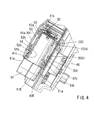
- the detail of this battery attachment section 50 is shown in FIG.2 and its subsequent figures.
- a lower part of a magazine case 41 of the driven-members-housing magazine 40 has a shape that is slightly swollen laterally, and a battery holder 52 is supported within the swollen portion 41 a.
- the magazine case 41 has a so-called two-piece structure. By use of this two-piece structure, the battery holder 52 is mounted and supported at a lower part of the magazine case 41.
- the battery holder 52 has a substantially tubular shape, and in its outer circumferential side two elongated protrusions 52a and 52b are integrally formed along its entire circumference.
- an upper side means a forward side in a striking direction of driven members (toward the upper side in the figures) and a lower side means a backward side against the striking direction of driven members (toward the lower side in the figures).
- two engaging projections 41b and 41c are formed integrally on the inner side of the swollen portion 41a of the magazine case 41.
- the battery holder 52 is supported in the swollen portion 41a of the magazine case 41 in a state in which the upper rubber ring 53 is elastically interposed between the upper engaging projection 41b and the upper elongated protrusion 52a, and the lower rubber ring 54 is elastically interposed between the lower engaging projection 41c and the lower elongated protrusion 52b.
- Two elongated protrusions 52a and 52b are not in contact with the magazine case 41 side. Further, other portions of the battery holder 52 do not hold in contact with or are not in contact with the magazine case 41, either.
- the battery holder 52 is supported in a floating state in the swollen portion 41a of the magazine case 41 in a state in which only two rubber rings 53, 54 are in contact with the magazine case 41.
- the battery holder 52 is supported in the magazine case 41 via only rubber rings 53 and 54, which are elastic material, in a floating state, and thus the vibration or the impact (a force of reaction caused by a striking movement) occurred at the tool main body 10 side can be blocked and all of the vibration or the impact may not be transmitted to the battery holder 52.
- the vibration etc. transmitted to the battery holder 52 can be greatly reduced.
- a battery pack 51 is attached to this battery holder 52 supported in a floating state.
- a terminal block 55 is mounted in the rear part of the battery holder 52.
- This terminal block 55 is electrically connected to a control circuit of the tool main body 10 via lead wires that is not shown.
- the battery pack 51 attached to the battery holder 52 is electrically connected to the control circuit of the tool main body 10 side via this terminal block 55.
- push buttons 51a, 51a for a removing operation are provided at both sides of a lowered portion of the battery pack 51 in an attaching direction.
- the double push buttons 51a, 51a are provided in a biased state in an opening direction respectively (toward a mutually separating direction).
- engaging claws 51b are integrally provided respectively.
- both of the engaging claws 51b, 51b are elastically engaged respectively with engaging concave portion 52c, 52c provided on the inner side of the opening of the battery holder 52. And thus, the attaching state of the battery pack 51 with respect to the battery holder 52 is maintained.
- the battery pack 51 is attached in a state in which an end portion 51E of the rear side of the battery pack 51 in the attaching direction is located such that the end portion 51E may not protrude from an end portion 40E of the driven-members-housing magazine 40, as shown in the figure.
- a push operation of the push buttons 51a with a fingertip can detach the engaging claws 51b from the engaging concave portion 52c, and in this disengagement state the battery pack 51 can be pulled off and removed from the battery holder 52.
- the battery pack 51 is attached to the terminal blocks of the driven-members-housing magazine 40 via the battery holder 52.
- the battery holder 52 is supported in a floating state (elastically supported) with respect to the magazine case 41 in a state in which the battery holder 52 is elastically in contact with only the rubber rings 53, 54 by elastically pressing and interposing the two rubber rings 53, 54, which are fitted to the outer circumference of the battery holder 52 between the elongated protrusions 52a, 52b and the engaging projections 41b, 41c of the magazine case 41 side.
- the vibration or the impact caused by the drive movement of the tool main body 10 can be blocked with both the rubber rings 53, 54, and the transmission of the vibration or the impact to the battery holder 52, and eventually to the battery pack 51, can be greatly reduced. Since the vibration or the impact transmitted to the battery pack 51 can be greatly reduced in this way, an electrically contact state and an attaching state with respect to the tool main body 10 side of the battery pack 51 can be maintained in a good condition, and thus a failure such as adhesion or chattering of electric contacts can be prevented (protection of electrical contacts), and an unintended falling of the battery pack 51 can be prevented (protection of the battery pack itself).
- the configuration is such that the battery pack 51 is attached in the rear end portion of the driven-members-housing magazine 40 and in a far-away portion from a driving axis of the tool main body 10.
- the battery pack 51 is not subject to the influence of the vibration or the impact of the tool main body 10 side.
- the attaching direction of the battery pack 51 with respect to the battery holder 52 corresponds with the feed direction of the driven-members-housing magazine 40, and thus the attaching direction of the battery pack 51 is configured in a cross direction with respect to the striking direction of the tool main body 10 (toward a moving direction of the driver 14).
- the battery pack 51 is not subject to the influence of the vibration or the impact that causes a failure such as chattering of electric contacts or an unintended falling by the disconnection from the engaging claws 51b.
- the battery pack 51 is attached in a state in which the rear end portion 51E of the battery pack 51 does not protrude from the rear end portion 40E of the driven-members-housing magazine 40. For this reason, in case that a user unintentionally drops the driving tool 1, the rear end portion 40E of the magazine 40 may hit a floor etc. but the battery pack 51 can be prevented from directly hitting a floor, and thus damage of the battery pack 51 can be prevented.
- the key is to interpose elastic materials between the battery holder and the tool main body 10 side without rigidly connecting the battery holder and the tool main body 10 and to support the battery holder in the tool main body 10 side in a floating state in which the vibration or the impact may be blocked, and thus a similar function effect can be obtained.
- a gas combustion type nail driver is exemplified as an example of driving tools, but the embodiment can also be applied to driving tools in which a battery pack, which can be removed for charging or can be detached and exchanged, may be used as a power source for an electric motor or other electric appliances.
Landscapes
- Engineering & Computer Science (AREA)
- Mechanical Engineering (AREA)
- Chemical & Material Sciences (AREA)
- Combustion & Propulsion (AREA)
- Portable Nailing Machines And Staplers (AREA)
- Battery Mounting, Suspending (AREA)
- Portable Power Tools In General (AREA)
Applications Claiming Priority (2)
| Application Number | Priority Date | Filing Date | Title |
|---|---|---|---|
| JP2007251347A JP5242108B2 (ja) | 2007-09-27 | 2007-09-27 | 打ち込み工具 |
| PCT/JP2008/066820 WO2009041336A1 (ja) | 2007-09-27 | 2008-09-18 | 打ち込み工具 |
Publications (3)
| Publication Number | Publication Date |
|---|---|
| EP2193884A1 true EP2193884A1 (de) | 2010-06-09 |
| EP2193884A4 EP2193884A4 (de) | 2011-05-25 |
| EP2193884B1 EP2193884B1 (de) | 2015-01-21 |
Family
ID=40511222
Family Applications (1)
| Application Number | Title | Priority Date | Filing Date |
|---|---|---|---|
| EP08833260.6A Active EP2193884B1 (de) | 2007-09-27 | 2008-09-18 | Einschlagwerkzeug |
Country Status (4)
| Country | Link |
|---|---|
| US (1) | US8123098B2 (de) |
| EP (1) | EP2193884B1 (de) |
| JP (1) | JP5242108B2 (de) |
| WO (1) | WO2009041336A1 (de) |
Cited By (5)
| Publication number | Priority date | Publication date | Assignee | Title |
|---|---|---|---|---|
| WO2013003502A1 (en) * | 2011-06-30 | 2013-01-03 | Illinois Tool Works Inc. | Fuel cell adapter |
| EP3321038A3 (de) * | 2016-11-09 | 2018-07-25 | TTI (Macao Commercial Offshore) Limited | Gasfederbefestigungstreiber |
| CN110326125A (zh) * | 2017-01-24 | 2019-10-11 | 创科(澳门离岸商业服务)有限公司 | 用于电动工具的电池端子保持器 |
| WO2023079091A1 (de) * | 2021-11-08 | 2023-05-11 | Wahl Gmbh | Haarschneidevorrichtung, ladegerät und akkumulator |
| JP2023537673A (ja) * | 2020-07-27 | 2023-09-05 | ゼジアン リゼリ テクノロジー カンパニー リミテッド | 手持ち式工具 |
Families Citing this family (20)
| Publication number | Priority date | Publication date | Assignee | Title |
|---|---|---|---|---|
| US8591242B2 (en) * | 2010-04-08 | 2013-11-26 | Illinois Tool Works Inc. | Floating battery contact module for a power tool |
| US9461281B2 (en) | 2010-10-08 | 2016-10-04 | Milwaukee Electric Tool Corporation | Battery retention system for a power tool |
| JP2012166309A (ja) * | 2011-02-15 | 2012-09-06 | Makita Corp | 燃焼式の打込み機 |
| JP5741233B2 (ja) * | 2011-06-10 | 2015-07-01 | マックス株式会社 | 燃料容器保持構造 |
| WO2013139372A1 (en) | 2012-03-19 | 2013-09-26 | Husqvarna Ab | Power adapter for cordless power tools |
| CN104303331A (zh) | 2012-03-19 | 2015-01-21 | 胡斯华纳有限公司 | 用于背包能源的载体系统、能源以及背包能源组件 |
| US20150328764A1 (en) | 2013-02-01 | 2015-11-19 | Makita Corporation | Power tool |
| DE102013202027B4 (de) * | 2013-02-07 | 2024-09-26 | Robert Bosch Gmbh | Tragbare Werkzeugmaschine mit einem Haupt- und einem Bügelgriff |
| US10232479B2 (en) * | 2013-05-06 | 2019-03-19 | Milwaukee Electric Tool Corporation | Power tool including a battery pack isolation system |
| JP6501414B2 (ja) * | 2014-03-25 | 2019-04-17 | 株式会社マキタ | 打撃工具 |
| USD795570S1 (en) | 2016-06-23 | 2017-08-29 | James E. Lacroix | Drill caddy |
| USD900575S1 (en) | 2018-09-26 | 2020-11-03 | Milwaukee Electric Tool Corporation | Powered fastener driver |
| EP3653343A1 (de) * | 2018-11-13 | 2020-05-20 | Hilti Aktiengesellschaft | Akkubetriebene handwerkzeugmaschine |
| IT201900004273A1 (it) * | 2019-03-25 | 2020-09-25 | Emak Spa | Attrezzo da lavoro dotato di un elemento smorzatore |
| JP7516076B2 (ja) * | 2020-03-10 | 2024-07-16 | 株式会社マキタ | 電動工具 |
| CN116472142A (zh) | 2020-10-28 | 2023-07-21 | 罗伯特·博世有限公司 | 动力工具 |
| US12080906B2 (en) | 2021-01-12 | 2024-09-03 | Milwaukee Electric Tool Corporation | Power tool battery pack receptacle |
| EP4351834A4 (de) | 2021-06-09 | 2025-12-31 | Black & Decker Inc | Batteriepackisolationssystem |
| EP4302926B1 (de) | 2022-06-16 | 2025-08-06 | Milwaukee Electric Tool Corporation | Kompaktes schlagwerkzeug |
| DE102023119516A1 (de) * | 2023-03-31 | 2024-10-02 | Andreas Stihl Ag & Co. Kg | Handgeführtes, im Einsatz tragbares Arbeitsgerät |
Family Cites Families (17)
| Publication number | Priority date | Publication date | Assignee | Title |
|---|---|---|---|---|
| JPS58106758A (ja) * | 1981-12-17 | 1983-06-25 | Hitachi Koki Co Ltd | コ−ドレス工具の電池端子装置 |
| JPS59193683U (ja) * | 1983-06-10 | 1984-12-22 | 株式会社 マキタ電機製作所 | 釘打機における釘ベルトマガジン |
| US5681667A (en) * | 1994-08-11 | 1997-10-28 | Black & Decker Inc. | Battery pack retaining latch for cordless device |
| JPH0899271A (ja) * | 1994-10-04 | 1996-04-16 | Makita Corp | エア釘打機の釘送り装置 |
| JPH10296660A (ja) | 1997-04-25 | 1998-11-10 | Hitachi Koki Co Ltd | 電池式携帯用工具 |
| US6012622A (en) * | 1998-04-20 | 2000-01-11 | Illinois Tool Works Inc. | Fastener driving tool for trim applications |
| US6357534B1 (en) * | 1998-04-20 | 2002-03-19 | Illinois Tool Works Inc | Battery pack latching assembly for fastener driving tool |
| JP2001325932A (ja) * | 2000-05-16 | 2001-11-22 | Makita Corp | 充電式電動工具 |
| US6619527B1 (en) | 2000-10-10 | 2003-09-16 | Illinois Tool Works Inc. | Combustion powered tool suspension for iron core fan motor |
| JP4269567B2 (ja) | 2002-04-05 | 2009-05-27 | 日立工機株式会社 | 電池工具 |
| US6786381B2 (en) * | 2002-05-24 | 2004-09-07 | Illinois Tool Works Inc. | Anti-oxidant battery contacts for fastener-driving tool |
| US7040520B2 (en) * | 2002-09-12 | 2006-05-09 | Illinois Tool Works Inc. | Fan motor suspension mount for a combustion-powered tool |
| DE10318947A1 (de) | 2003-04-26 | 2004-11-18 | Robert Bosch Gmbh | Elektrische Handwerkzeugmaschine mit Akkupack |
| JP4145728B2 (ja) * | 2003-06-12 | 2008-09-03 | 株式会社マキタ | 打ち込み機 |
| JP4593999B2 (ja) * | 2004-08-09 | 2010-12-08 | 日本パワーファスニング株式会社 | 打ち込み工具 |
| JP4930670B2 (ja) | 2005-04-01 | 2012-05-16 | マックス株式会社 | ガス燃焼式打込み工具のモータ保持機構 |
| DE102005052428B4 (de) | 2005-11-03 | 2015-06-18 | Robert Bosch Gmbh | Elektrowerkzeugmaschine |
-
2007
- 2007-09-27 JP JP2007251347A patent/JP5242108B2/ja active Active
-
2008
- 2008-09-18 EP EP08833260.6A patent/EP2193884B1/de active Active
- 2008-09-18 WO PCT/JP2008/066820 patent/WO2009041336A1/ja not_active Ceased
- 2008-09-18 US US12/679,180 patent/US8123098B2/en active Active
Cited By (10)
| Publication number | Priority date | Publication date | Assignee | Title |
|---|---|---|---|---|
| WO2013003502A1 (en) * | 2011-06-30 | 2013-01-03 | Illinois Tool Works Inc. | Fuel cell adapter |
| EP3321038A3 (de) * | 2016-11-09 | 2018-07-25 | TTI (Macao Commercial Offshore) Limited | Gasfederbefestigungstreiber |
| US10702980B2 (en) | 2016-11-09 | 2020-07-07 | Tti (Macao Commercial Offshore) Limited | Gas spring fastener driver |
| CN110326125A (zh) * | 2017-01-24 | 2019-10-11 | 创科(澳门离岸商业服务)有限公司 | 用于电动工具的电池端子保持器 |
| EP3574536A4 (de) * | 2017-01-24 | 2020-10-21 | TTI (Macao Commercial Offshore) Limited | Batterieklemmenhalter für elektrowerkzeuge |
| US11440176B2 (en) | 2017-01-24 | 2022-09-13 | Techtronic Cordless Gp | Battery terminal holder for electric tools |
| CN110326125B (zh) * | 2017-01-24 | 2023-02-21 | 创科(澳门离岸商业服务)有限公司 | 用于电动工具的电池端子保持器 |
| JP2023537673A (ja) * | 2020-07-27 | 2023-09-05 | ゼジアン リゼリ テクノロジー カンパニー リミテッド | 手持ち式工具 |
| EP4190509A4 (de) * | 2020-07-27 | 2024-10-09 | Zhejiang Litheli Technology Co., Ltd | Handwerkzeug |
| WO2023079091A1 (de) * | 2021-11-08 | 2023-05-11 | Wahl Gmbh | Haarschneidevorrichtung, ladegerät und akkumulator |
Also Published As
| Publication number | Publication date |
|---|---|
| JP2009078340A (ja) | 2009-04-16 |
| EP2193884B1 (de) | 2015-01-21 |
| US20100224666A1 (en) | 2010-09-09 |
| JP5242108B2 (ja) | 2013-07-24 |
| US8123098B2 (en) | 2012-02-28 |
| EP2193884A4 (de) | 2011-05-25 |
| WO2009041336A1 (ja) | 2009-04-02 |
Similar Documents
| Publication | Publication Date | Title |
|---|---|---|
| EP2193884B1 (de) | Einschlagwerkzeug | |
| US10562167B2 (en) | Striking tool | |
| US12090617B2 (en) | Power tool | |
| US10875168B2 (en) | Power tool | |
| US11011031B2 (en) | Tool and electric tool | |
| US20210237249A1 (en) | Impact tool | |
| US10780564B2 (en) | Power tool | |
| CN111065491A (zh) | 电气设备 | |
| JP4922031B2 (ja) | 携帯用工具 | |
| CN107787667A (zh) | 手柄组件及具有其的园林工具 | |
| JP7119764B2 (ja) | 工具、工具セット、電動工具および電動工具セット | |
| EP1693156B1 (de) | Verbrennungskraftbetriebenes Werkzeug mit Schalterschützanordnung | |
| EP2174753A1 (de) | Brennkraftbetriebenes eintreibwerkzeug | |
| US20200212414A1 (en) | Electric device | |
| US20230182279A1 (en) | Work machine | |
| JP6606941B2 (ja) | 可搬型動力工具 | |
| JP6844700B2 (ja) | 電動工具 | |
| CN221390892U (zh) | 一种锂电电池可拆卸的电锤 | |
| CN218985078U (zh) | 一种电动式链锯 | |
| JP5733068B2 (ja) | 打ち込み工具 | |
| CN110637398A (zh) | 冲击工具 | |
| JP5192674B2 (ja) | 電動工具 | |
| JP2020163541A (ja) | 電動工具 | |
| CN120206451A (zh) | 冲击工具 | |
| WO2008060281A1 (en) | Power source conversion and software lockout for corded power nailer |
Legal Events
| Date | Code | Title | Description |
|---|---|---|---|
| PUAI | Public reference made under article 153(3) epc to a published international application that has entered the european phase |
Free format text: ORIGINAL CODE: 0009012 |
|
| 17P | Request for examination filed |
Effective date: 20100323 |
|
| AK | Designated contracting states |
Kind code of ref document: A1 Designated state(s): AT BE BG CH CY CZ DE DK EE ES FI FR GB GR HR HU IE IS IT LI LT LU LV MC MT NL NO PL PT RO SE SI SK TR |
|
| AX | Request for extension of the european patent |
Extension state: AL BA MK RS |
|
| DAX | Request for extension of the european patent (deleted) | ||
| A4 | Supplementary search report drawn up and despatched |
Effective date: 20110427 |
|
| GRAP | Despatch of communication of intention to grant a patent |
Free format text: ORIGINAL CODE: EPIDOSNIGR1 |
|
| INTG | Intention to grant announced |
Effective date: 20141103 |
|
| GRAS | Grant fee paid |
Free format text: ORIGINAL CODE: EPIDOSNIGR3 |
|
| GRAA | (expected) grant |
Free format text: ORIGINAL CODE: 0009210 |
|
| AK | Designated contracting states |
Kind code of ref document: B1 Designated state(s): AT BE BG CH CY CZ DE DK EE ES FI FR GB GR HR HU IE IS IT LI LT LU LV MC MT NL NO PL PT RO SE SI SK TR |
|
| REG | Reference to a national code |
Ref country code: GB Ref legal event code: FG4D |
|
| REG | Reference to a national code |
Ref country code: CH Ref legal event code: EP |
|
| REG | Reference to a national code |
Ref country code: IE Ref legal event code: FG4D |
|
| REG | Reference to a national code |
Ref country code: DE Ref legal event code: R096 Ref document number: 602008036487 Country of ref document: DE Effective date: 20150305 |
|
| REG | Reference to a national code |
Ref country code: AT Ref legal event code: REF Ref document number: 708938 Country of ref document: AT Kind code of ref document: T Effective date: 20150315 |
|
| REG | Reference to a national code |
Ref country code: NL Ref legal event code: VDEP Effective date: 20150121 |
|
| REG | Reference to a national code |
Ref country code: AT Ref legal event code: MK05 Ref document number: 708938 Country of ref document: AT Kind code of ref document: T Effective date: 20150121 |
|
| REG | Reference to a national code |
Ref country code: LT Ref legal event code: MG4D |
|
| PG25 | Lapsed in a contracting state [announced via postgrant information from national office to epo] |
Ref country code: HR Free format text: LAPSE BECAUSE OF FAILURE TO SUBMIT A TRANSLATION OF THE DESCRIPTION OR TO PAY THE FEE WITHIN THE PRESCRIBED TIME-LIMIT Effective date: 20150121 Ref country code: NO Free format text: LAPSE BECAUSE OF FAILURE TO SUBMIT A TRANSLATION OF THE DESCRIPTION OR TO PAY THE FEE WITHIN THE PRESCRIBED TIME-LIMIT Effective date: 20150421 Ref country code: LT Free format text: LAPSE BECAUSE OF FAILURE TO SUBMIT A TRANSLATION OF THE DESCRIPTION OR TO PAY THE FEE WITHIN THE PRESCRIBED TIME-LIMIT Effective date: 20150121 Ref country code: FI Free format text: LAPSE BECAUSE OF FAILURE TO SUBMIT A TRANSLATION OF THE DESCRIPTION OR TO PAY THE FEE WITHIN THE PRESCRIBED TIME-LIMIT Effective date: 20150121 Ref country code: ES Free format text: LAPSE BECAUSE OF FAILURE TO SUBMIT A TRANSLATION OF THE DESCRIPTION OR TO PAY THE FEE WITHIN THE PRESCRIBED TIME-LIMIT Effective date: 20150121 Ref country code: SE Free format text: LAPSE BECAUSE OF FAILURE TO SUBMIT A TRANSLATION OF THE DESCRIPTION OR TO PAY THE FEE WITHIN THE PRESCRIBED TIME-LIMIT Effective date: 20150121 Ref country code: BG Free format text: LAPSE BECAUSE OF FAILURE TO SUBMIT A TRANSLATION OF THE DESCRIPTION OR TO PAY THE FEE WITHIN THE PRESCRIBED TIME-LIMIT Effective date: 20150421 |
|
| PG25 | Lapsed in a contracting state [announced via postgrant information from national office to epo] |
Ref country code: LV Free format text: LAPSE BECAUSE OF FAILURE TO SUBMIT A TRANSLATION OF THE DESCRIPTION OR TO PAY THE FEE WITHIN THE PRESCRIBED TIME-LIMIT Effective date: 20150121 Ref country code: AT Free format text: LAPSE BECAUSE OF FAILURE TO SUBMIT A TRANSLATION OF THE DESCRIPTION OR TO PAY THE FEE WITHIN THE PRESCRIBED TIME-LIMIT Effective date: 20150121 Ref country code: PL Free format text: LAPSE BECAUSE OF FAILURE TO SUBMIT A TRANSLATION OF THE DESCRIPTION OR TO PAY THE FEE WITHIN THE PRESCRIBED TIME-LIMIT Effective date: 20150121 Ref country code: NL Free format text: LAPSE BECAUSE OF FAILURE TO SUBMIT A TRANSLATION OF THE DESCRIPTION OR TO PAY THE FEE WITHIN THE PRESCRIBED TIME-LIMIT Effective date: 20150121 Ref country code: GR Free format text: LAPSE BECAUSE OF FAILURE TO SUBMIT A TRANSLATION OF THE DESCRIPTION OR TO PAY THE FEE WITHIN THE PRESCRIBED TIME-LIMIT Effective date: 20150422 Ref country code: IS Free format text: LAPSE BECAUSE OF FAILURE TO SUBMIT A TRANSLATION OF THE DESCRIPTION OR TO PAY THE FEE WITHIN THE PRESCRIBED TIME-LIMIT Effective date: 20150521 |
|
| REG | Reference to a national code |
Ref country code: DE Ref legal event code: R097 Ref document number: 602008036487 Country of ref document: DE |
|
| PG25 | Lapsed in a contracting state [announced via postgrant information from national office to epo] |
Ref country code: RO Free format text: LAPSE BECAUSE OF FAILURE TO SUBMIT A TRANSLATION OF THE DESCRIPTION OR TO PAY THE FEE WITHIN THE PRESCRIBED TIME-LIMIT Effective date: 20150121 Ref country code: DK Free format text: LAPSE BECAUSE OF FAILURE TO SUBMIT A TRANSLATION OF THE DESCRIPTION OR TO PAY THE FEE WITHIN THE PRESCRIBED TIME-LIMIT Effective date: 20150121 Ref country code: EE Free format text: LAPSE BECAUSE OF FAILURE TO SUBMIT A TRANSLATION OF THE DESCRIPTION OR TO PAY THE FEE WITHIN THE PRESCRIBED TIME-LIMIT Effective date: 20150121 Ref country code: CZ Free format text: LAPSE BECAUSE OF FAILURE TO SUBMIT A TRANSLATION OF THE DESCRIPTION OR TO PAY THE FEE WITHIN THE PRESCRIBED TIME-LIMIT Effective date: 20150121 Ref country code: SK Free format text: LAPSE BECAUSE OF FAILURE TO SUBMIT A TRANSLATION OF THE DESCRIPTION OR TO PAY THE FEE WITHIN THE PRESCRIBED TIME-LIMIT Effective date: 20150121 |
|
| PLBE | No opposition filed within time limit |
Free format text: ORIGINAL CODE: 0009261 |
|
| STAA | Information on the status of an ep patent application or granted ep patent |
Free format text: STATUS: NO OPPOSITION FILED WITHIN TIME LIMIT |
|
| 26N | No opposition filed |
Effective date: 20151022 |
|
| PG25 | Lapsed in a contracting state [announced via postgrant information from national office to epo] |
Ref country code: IT Free format text: LAPSE BECAUSE OF FAILURE TO SUBMIT A TRANSLATION OF THE DESCRIPTION OR TO PAY THE FEE WITHIN THE PRESCRIBED TIME-LIMIT Effective date: 20150121 |
|
| PG25 | Lapsed in a contracting state [announced via postgrant information from national office to epo] |
Ref country code: SI Free format text: LAPSE BECAUSE OF FAILURE TO SUBMIT A TRANSLATION OF THE DESCRIPTION OR TO PAY THE FEE WITHIN THE PRESCRIBED TIME-LIMIT Effective date: 20150121 |
|
| PG25 | Lapsed in a contracting state [announced via postgrant information from national office to epo] |
Ref country code: LU Free format text: LAPSE BECAUSE OF FAILURE TO SUBMIT A TRANSLATION OF THE DESCRIPTION OR TO PAY THE FEE WITHIN THE PRESCRIBED TIME-LIMIT Effective date: 20150918 Ref country code: MC Free format text: LAPSE BECAUSE OF FAILURE TO SUBMIT A TRANSLATION OF THE DESCRIPTION OR TO PAY THE FEE WITHIN THE PRESCRIBED TIME-LIMIT Effective date: 20150121 |
|
| REG | Reference to a national code |
Ref country code: CH Ref legal event code: PL |
|
| PG25 | Lapsed in a contracting state [announced via postgrant information from national office to epo] |
Ref country code: BE Free format text: LAPSE BECAUSE OF FAILURE TO SUBMIT A TRANSLATION OF THE DESCRIPTION OR TO PAY THE FEE WITHIN THE PRESCRIBED TIME-LIMIT Effective date: 20150121 |
|
| REG | Reference to a national code |
Ref country code: IE Ref legal event code: MM4A |
|
| PG25 | Lapsed in a contracting state [announced via postgrant information from national office to epo] |
Ref country code: LI Free format text: LAPSE BECAUSE OF NON-PAYMENT OF DUE FEES Effective date: 20150930 Ref country code: IE Free format text: LAPSE BECAUSE OF NON-PAYMENT OF DUE FEES Effective date: 20150918 Ref country code: CH Free format text: LAPSE BECAUSE OF NON-PAYMENT OF DUE FEES Effective date: 20150930 |
|
| REG | Reference to a national code |
Ref country code: FR Ref legal event code: PLFP Year of fee payment: 9 |
|
| PG25 | Lapsed in a contracting state [announced via postgrant information from national office to epo] |
Ref country code: MT Free format text: LAPSE BECAUSE OF FAILURE TO SUBMIT A TRANSLATION OF THE DESCRIPTION OR TO PAY THE FEE WITHIN THE PRESCRIBED TIME-LIMIT Effective date: 20150121 |
|
| PG25 | Lapsed in a contracting state [announced via postgrant information from national office to epo] |
Ref country code: HU Free format text: LAPSE BECAUSE OF FAILURE TO SUBMIT A TRANSLATION OF THE DESCRIPTION OR TO PAY THE FEE WITHIN THE PRESCRIBED TIME-LIMIT; INVALID AB INITIO Effective date: 20080918 |
|
| PG25 | Lapsed in a contracting state [announced via postgrant information from national office to epo] |
Ref country code: CY Free format text: LAPSE BECAUSE OF FAILURE TO SUBMIT A TRANSLATION OF THE DESCRIPTION OR TO PAY THE FEE WITHIN THE PRESCRIBED TIME-LIMIT Effective date: 20150121 |
|
| REG | Reference to a national code |
Ref country code: FR Ref legal event code: PLFP Year of fee payment: 10 |
|
| PG25 | Lapsed in a contracting state [announced via postgrant information from national office to epo] |
Ref country code: TR Free format text: LAPSE BECAUSE OF FAILURE TO SUBMIT A TRANSLATION OF THE DESCRIPTION OR TO PAY THE FEE WITHIN THE PRESCRIBED TIME-LIMIT Effective date: 20150121 |
|
| PG25 | Lapsed in a contracting state [announced via postgrant information from national office to epo] |
Ref country code: PT Free format text: LAPSE BECAUSE OF FAILURE TO SUBMIT A TRANSLATION OF THE DESCRIPTION OR TO PAY THE FEE WITHIN THE PRESCRIBED TIME-LIMIT Effective date: 20150121 |
|
| REG | Reference to a national code |
Ref country code: FR Ref legal event code: PLFP Year of fee payment: 11 |
|
| PGFP | Annual fee paid to national office [announced via postgrant information from national office to epo] |
Ref country code: DE Payment date: 20250730 Year of fee payment: 18 |
|
| PGFP | Annual fee paid to national office [announced via postgrant information from national office to epo] |
Ref country code: GB Payment date: 20250731 Year of fee payment: 18 |
|
| PGFP | Annual fee paid to national office [announced via postgrant information from national office to epo] |
Ref country code: FR Payment date: 20250808 Year of fee payment: 18 |