EP2193909B1 - Refroidisseur d'huile pour automobile et procédé de fabrication d'un assemblage de liaison comprenant un tel refroidisseur d'huile - Google Patents
Refroidisseur d'huile pour automobile et procédé de fabrication d'un assemblage de liaison comprenant un tel refroidisseur d'huile Download PDFInfo
- Publication number
- EP2193909B1 EP2193909B1 EP09176982A EP09176982A EP2193909B1 EP 2193909 B1 EP2193909 B1 EP 2193909B1 EP 09176982 A EP09176982 A EP 09176982A EP 09176982 A EP09176982 A EP 09176982A EP 2193909 B1 EP2193909 B1 EP 2193909B1
- Authority
- EP
- European Patent Office
- Prior art keywords
- oil cooler
- base plate
- segment
- heated
- anchor
- Prior art date
- Legal status (The legal status is an assumption and is not a legal conclusion. Google has not performed a legal analysis and makes no representation as to the accuracy of the status listed.)
- Not-in-force
Links
- 238000004519 manufacturing process Methods 0.000 title claims description 6
- 238000005452 bending Methods 0.000 claims description 4
- 238000004080 punching Methods 0.000 claims description 4
- 238000001816 cooling Methods 0.000 claims description 2
- 230000002093 peripheral effect Effects 0.000 claims 1
- 238000010438 heat treatment Methods 0.000 description 11
- 230000006698 induction Effects 0.000 description 7
- 239000000463 material Substances 0.000 description 3
- 238000003860 storage Methods 0.000 description 3
- 230000001419 dependent effect Effects 0.000 description 2
- 238000000034 method Methods 0.000 description 2
- 238000003825 pressing Methods 0.000 description 2
- 238000004873 anchoring Methods 0.000 description 1
- 150000001875 compounds Chemical class 0.000 description 1
- 238000006073 displacement reaction Methods 0.000 description 1
- 239000012530 fluid Substances 0.000 description 1
- 238000009434 installation Methods 0.000 description 1
- 239000002184 metal Substances 0.000 description 1
- 230000000149 penetrating effect Effects 0.000 description 1
- 238000002360 preparation method Methods 0.000 description 1
- 238000000275 quality assurance Methods 0.000 description 1
- 230000005855 radiation Effects 0.000 description 1
- 239000000779 smoke Substances 0.000 description 1
- 239000007787 solid Substances 0.000 description 1
- 238000002604 ultrasonography Methods 0.000 description 1
Images

Classifications
-
- B—PERFORMING OPERATIONS; TRANSPORTING
- B29—WORKING OF PLASTICS; WORKING OF SUBSTANCES IN A PLASTIC STATE IN GENERAL
- B29C—SHAPING OR JOINING OF PLASTICS; SHAPING OF MATERIAL IN A PLASTIC STATE, NOT OTHERWISE PROVIDED FOR; AFTER-TREATMENT OF THE SHAPED PRODUCTS, e.g. REPAIRING
- B29C66/00—General aspects of processes or apparatus for joining preformed parts
- B29C66/40—General aspects of joining substantially flat articles, e.g. plates, sheets or web-like materials; Making flat seams in tubular or hollow articles; Joining single elements to substantially flat surfaces
- B29C66/47—Joining single elements to sheets, plates or other substantially flat surfaces
- B29C66/474—Joining single elements to sheets, plates or other substantially flat surfaces said single elements being substantially non-flat
-
- B—PERFORMING OPERATIONS; TRANSPORTING
- B29—WORKING OF PLASTICS; WORKING OF SUBSTANCES IN A PLASTIC STATE IN GENERAL
- B29C—SHAPING OR JOINING OF PLASTICS; SHAPING OF MATERIAL IN A PLASTIC STATE, NOT OTHERWISE PROVIDED FOR; AFTER-TREATMENT OF THE SHAPED PRODUCTS, e.g. REPAIRING
- B29C65/00—Joining or sealing of preformed parts, e.g. welding of plastics materials; Apparatus therefor
- B29C65/02—Joining or sealing of preformed parts, e.g. welding of plastics materials; Apparatus therefor by heating, with or without pressure
- B29C65/44—Joining a heated non plastics element to a plastics element
-
- B—PERFORMING OPERATIONS; TRANSPORTING
- B29—WORKING OF PLASTICS; WORKING OF SUBSTANCES IN A PLASTIC STATE IN GENERAL
- B29C—SHAPING OR JOINING OF PLASTICS; SHAPING OF MATERIAL IN A PLASTIC STATE, NOT OTHERWISE PROVIDED FOR; AFTER-TREATMENT OF THE SHAPED PRODUCTS, e.g. REPAIRING
- B29C65/00—Joining or sealing of preformed parts, e.g. welding of plastics materials; Apparatus therefor
- B29C65/02—Joining or sealing of preformed parts, e.g. welding of plastics materials; Apparatus therefor by heating, with or without pressure
- B29C65/44—Joining a heated non plastics element to a plastics element
- B29C65/46—Joining a heated non plastics element to a plastics element heated by induction
-
- B—PERFORMING OPERATIONS; TRANSPORTING
- B29—WORKING OF PLASTICS; WORKING OF SUBSTANCES IN A PLASTIC STATE IN GENERAL
- B29C—SHAPING OR JOINING OF PLASTICS; SHAPING OF MATERIAL IN A PLASTIC STATE, NOT OTHERWISE PROVIDED FOR; AFTER-TREATMENT OF THE SHAPED PRODUCTS, e.g. REPAIRING
- B29C66/00—General aspects of processes or apparatus for joining preformed parts
- B29C66/01—General aspects dealing with the joint area or with the area to be joined
- B29C66/05—Particular design of joint configurations
- B29C66/303—Particular design of joint configurations the joint involving an anchoring effect
- B29C66/3032—Particular design of joint configurations the joint involving an anchoring effect making use of protrusions or cavities belonging to at least one of the parts to be joined
- B29C66/30321—Particular design of joint configurations the joint involving an anchoring effect making use of protrusions or cavities belonging to at least one of the parts to be joined making use of protrusions belonging to at least one of the parts to be joined
-
- F—MECHANICAL ENGINEERING; LIGHTING; HEATING; WEAPONS; BLASTING
- F28—HEAT EXCHANGE IN GENERAL
- F28F—DETAILS OF HEAT-EXCHANGE AND HEAT-TRANSFER APPARATUS, OF GENERAL APPLICATION
- F28F9/00—Casings; Header boxes; Auxiliary supports for elements; Auxiliary members within casings
- F28F9/001—Casings in the form of plate-like arrangements; Frames enclosing a heat exchange core
- F28F9/002—Casings in the form of plate-like arrangements; Frames enclosing a heat exchange core with fastening means for other structures
-
- B—PERFORMING OPERATIONS; TRANSPORTING
- B29—WORKING OF PLASTICS; WORKING OF SUBSTANCES IN A PLASTIC STATE IN GENERAL
- B29C—SHAPING OR JOINING OF PLASTICS; SHAPING OF MATERIAL IN A PLASTIC STATE, NOT OTHERWISE PROVIDED FOR; AFTER-TREATMENT OF THE SHAPED PRODUCTS, e.g. REPAIRING
- B29C66/00—General aspects of processes or apparatus for joining preformed parts
- B29C66/70—General aspects of processes or apparatus for joining preformed parts characterised by the composition, physical properties or the structure of the material of the parts to be joined; Joining with non-plastics material
- B29C66/74—Joining plastics material to non-plastics material
- B29C66/742—Joining plastics material to non-plastics material to metals or their alloys
-
- B—PERFORMING OPERATIONS; TRANSPORTING
- B29—WORKING OF PLASTICS; WORKING OF SUBSTANCES IN A PLASTIC STATE IN GENERAL
- B29K—INDEXING SCHEME ASSOCIATED WITH SUBCLASSES B29B, B29C OR B29D, RELATING TO MOULDING MATERIALS OR TO MATERIALS FOR MOULDS, REINFORCEMENTS, FILLERS OR PREFORMED PARTS, e.g. INSERTS
- B29K2305/00—Use of metals, their alloys or their compounds, as reinforcement
-
- B—PERFORMING OPERATIONS; TRANSPORTING
- B29—WORKING OF PLASTICS; WORKING OF SUBSTANCES IN A PLASTIC STATE IN GENERAL
- B29L—INDEXING SCHEME ASSOCIATED WITH SUBCLASS B29C, RELATING TO PARTICULAR ARTICLES
- B29L2031/00—Other particular articles
- B29L2031/30—Vehicles, e.g. ships or aircraft, or body parts thereof
- B29L2031/3055—Cars
-
- F—MECHANICAL ENGINEERING; LIGHTING; HEATING; WEAPONS; BLASTING
- F28—HEAT EXCHANGE IN GENERAL
- F28D—HEAT-EXCHANGE APPARATUS, NOT PROVIDED FOR IN ANOTHER SUBCLASS, IN WHICH THE HEAT-EXCHANGE MEDIA DO NOT COME INTO DIRECT CONTACT
- F28D21/00—Heat-exchange apparatus not covered by any of the groups F28D1/00 - F28D20/00
- F28D2021/0019—Other heat exchangers for particular applications; Heat exchange systems not otherwise provided for
- F28D2021/008—Other heat exchangers for particular applications; Heat exchange systems not otherwise provided for for vehicles
- F28D2021/0089—Oil coolers
Definitions
- the present invention relates to an oil cooler in a motor vehicle.
- the invention also relates to a method for producing a connection arrangement with such an oil cooler and a carrier element made of plastic.
- the present invention addresses the problem of providing an oil cooler which can be attached to another plastic component in a particularly simple and high-quality reproduction.
- the invention is based on the general idea, in an oil cooler of a motor vehicle, which usually has a base plate carrying the oil cooler, to provide projecting and easily heated portions of this base plate, these portions are provided with a hot embedable in a plastic support plate anchor geometry.
- the protruding portions are preferably as well as the entire base plate formed of metal and can be easily heated or heated by means of specially adapted induction heaters. In the heated state, the partial regions formed as anchor geometries are capable of penetrating into a carrier element formed of plastic and firmly anchoring there after cooling.
- the protruding portions can be made for example by a simple turn of appropriately punched sections of the base plate, the then bent portions are easy to heat by means of a template-like induction heating.
- the oil cooler according to the invention offers the great advantage that it is pressed directly into the support element formed of plastic after heating the protruding partial regions and so can be positively connected with this.
- An assembly of screw associated with the resulting high storage and logistics costs for the screws and nuts and the high cost of the installation effort, can be omitted, whereby the attachment of the oil cooler according to the invention can be made much simpler and cheaper.
- such a trained ⁇ lkuhler allows extremely reliable connection or attaching the same to a support element made of plastic, whereby a very accurate producible connection can be created, which is crucial for quality assurance.
- At least a portion of the anchor geometry has a knurling.
- a knurling for example in the manner of a herringbone pattern, produced when pressing the heated portion in the support member made of plastic teeth of the heated portion with the support member and thereby a particularly reliable, since fixed connection between the oil cooler and the support member.
- the knurling can generally include grooves, grooves and / or engravings, which are both simple and inexpensive to produce and on the other hand offer a high resistance against pulling out of the sub-areas of the support element.
- the base plate of Oil cooler edge side are on the base plate of Oil cooler edge side and optionally additionally provided in the form of central anchor geometry portions provided in particular in conjunction with the base plate in a single punching / bending operation step.
- the parts required for the attachment thus do not require a separate step, but can be produced together with the base plate. This can be done for example in a combined punching and bending tool, which first punched out the base plate and then finished transforms. As a result, a particularly efficient and therefore cost-effective production of the base plate of the oil cooler according to the invention is possible.
- an oil cooler 1 a base plate 2, on which a functional element 3 of the functional device 1 is attached.
- a base plate 2 on which a functional element 3 of the functional device 1 is attached.
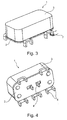
- On the base plate 2 according to the invention at least one protruding portion 4, according to the Figures 1 and 2 a total of six protruding portions 4, provided, which are formed as heatable and hot for mounting in a support plate, not shown plastic embedable anchor geometries.
- the protruding subregions are in accordance with the representations in Fig. 1 and 2 as angled Feet formed on which the oil cooler no comma can stand safely.
- the portion of the anchor geometry is provided with a knurling 5.
- the knurling 5 in this case consists of parallel grooves 3, although other patterns, for example a herringbone pattern, are to be understood by the term knurling. In particular, this is to think of a simple, an opposing knurl or a funnelrändel.
- a heating of the protruding portions 4 can be done for example by means of an induction heater 7 (see. Fig. 3 ).
- Such an induction heater 7 serves to heat the metallic portion 4 by means of magnetic induction.
- an induction heater 7 serves to heat the metallic portion 4 by means of magnetic induction.
- an electrically conductive body here the subregion 4. Due to the electrical resistance, this current induced in the subregion causes heating of subregion 4 at the points the current flow.
- the projecting portions 4 of the base plate 2 may have different embodiments, only two different are shown here.
- the subregions 4 and the base plate 2 are made of one piece or that the subregions 4 are made separately to the base plate 2 and connected in a further step with this. This would include in particular a so-called “built system” with, for example, riveted "inserts”. It is also conceivable that nozzles and / or cups are soldered to the base plate 2 with a corresponding anchor profile.
- central and formed as an anchor geometry portions 4 ' may be provided in addition to the edge side of the base plate 2 arranged portions 4 (see. Fig. 4 ).
- all portions 4, 4 ' is advantageously common that they can be produced together with the base plate 2 in a single punching and bending operation.
- the base plate 2 which is in itself flat, is first punched out, and then immediately reshaping, ie, the protruding partial regions 4, 4 'bend.
- the material for the support plate is not limited to plastic, but includes all materials in which the heated portions 4, 4 'of the functional device 1 can be pressed or embedded to produce a solid compound with material displacement.
- the oil cooler 1 by means of screws, generated connection between the oil cooler 1 and the carrier element, can be with the oil cooler 1 according to the invention provide an extremely simple and cost-effective connection, which has a high process reliability and a high reproducible quality. Since the screws previously required preferably omitted entirely, beyond the variety of parts and the associated storage and logistics costs can be reduced, so that even in comparison to the prior art cost-effective connection arrangement can be created.
- the inventive oil cooler 1 has protruding and heatable portions 4, which are preferably provided with a knurling 5, and via which the oil cooler 1 can be easily and reliably connected to another component, such as a plastic support element , In this case, in particular, a fully automated production of the connection between the oil cooler 1 and the carrier element to think.
Landscapes
- Engineering & Computer Science (AREA)
- Mechanical Engineering (AREA)
- Physics & Mathematics (AREA)
- Thermal Sciences (AREA)
- General Engineering & Computer Science (AREA)
- Connection Of Plates (AREA)
- Heat-Exchange Devices With Radiators And Conduit Assemblies (AREA)
Claims (4)
- Refroidisseur d'huile (1) dans un véhicule automobile comportant une plaque de base métallique (2), sur laquelle au moins une zone partielle en saillie (4, 4')est réalisée comme une géométrie d'ancrage métallique, qui en l'état chauffé est en mesure de pénétrer dans un élément porteur réalisé en plastique et de s'y ancrer solidement après le refroidissement, dans lequel sur la plaque de base (2) des zones partielles (4, 4') réalisées du côté des bords et en outre au milieu comme une géométrie d'ancrage sont prévues, lesquelles sont fabriquées conjointement à la plaque de base (2) lors d'une étape de travail de cintrage/ découpage à la presse commune.
- Refroidisseur d'huile selon la revendication 1, caractérisé en ce que au moins une zone partielle (4, 4') de la géométrie d'ancrage présente un moletage.
- Refroidisseur d'huile selon la revendication 1 ou 2, caractérisé en ce que au moins trois des zones partielles (4, 4') en saillie depuis la plaque de base (2) sont prévues, lesquelles sont réalisées comme les pieds de la plaque de base (2).
- Procédé de fabrication d'un dispositif de liaison, dans lequel :- au moins une zone partielle (4, 4') réalisée comme une géométrie d'ancrage d'une plaque de base (2) d'un refroidisseur d'huile (1) est chauffée,- au moins une zone partielle chauffée (4, 4') de la plaque de base (2) est enfoncée dans un élément porteur en plastique,- au moins une zone partielle (4, 4') refroidie et il se forme ainsi une liaison solide, indissoluble entre l'élément porteur et la plaque de base (2), respectivement le refroidisseur d'huile (1),- au moins une zone partielle (4, 4') de la plaque de base (2) est chauffée par induction.
Applications Claiming Priority (1)
| Application Number | Priority Date | Filing Date | Title |
|---|---|---|---|
| DE102008060153A DE102008060153A1 (de) | 2008-12-02 | 2008-12-02 | Funktionseinrichtung |
Publications (2)
| Publication Number | Publication Date |
|---|---|
| EP2193909A1 EP2193909A1 (fr) | 2010-06-09 |
| EP2193909B1 true EP2193909B1 (fr) | 2012-07-04 |
Family
ID=41786459
Family Applications (1)
| Application Number | Title | Priority Date | Filing Date |
|---|---|---|---|
| EP09176982A Not-in-force EP2193909B1 (fr) | 2008-12-02 | 2009-11-25 | Refroidisseur d'huile pour automobile et procédé de fabrication d'un assemblage de liaison comprenant un tel refroidisseur d'huile |
Country Status (2)
| Country | Link |
|---|---|
| EP (1) | EP2193909B1 (fr) |
| DE (1) | DE102008060153A1 (fr) |
Families Citing this family (3)
| Publication number | Priority date | Publication date | Assignee | Title |
|---|---|---|---|---|
| DE102010056170A1 (de) * | 2010-12-24 | 2012-06-28 | Volkswagen Ag | Thermoelektrisches Wärmetauschen |
| DE102016226198A1 (de) * | 2016-12-23 | 2018-06-28 | Robert Bosch Gmbh | Verfahren zur Befestigung eines ersten Bauteils an einem zweiten Bauteil, insbesondere zur Befestigung eines Halters für einen Sensor an einer Verkleidung für ein Fortbewegungsmittel |
| CN110573818B (zh) * | 2017-05-11 | 2021-10-08 | 沃尔沃卡车集团 | 热交换器设备 |
Family Cites Families (4)
| Publication number | Priority date | Publication date | Assignee | Title |
|---|---|---|---|---|
| DE1303323C2 (de) * | 1962-09-05 | 1972-03-23 | Telefunken Pat | Verfahren zum einbetten metallischer Durchführungselemente, insbesondere Lötstützpunkte in aus thermoplastischem Kunststoff bestehenden Teilen miniaturisierter Bauteile |
| JPS58168679A (ja) * | 1982-03-31 | 1983-10-05 | Yoshino Kogyosho Co Ltd | 金属プレ−トの合成樹脂製品への固定方法 |
| JPH0624769B2 (ja) * | 1985-11-28 | 1994-04-06 | 三井石油化学工業株式会社 | 樹脂製容器への樹脂製ニツプルの融着取付方法及び装置 |
| JPH09215079A (ja) * | 1996-01-30 | 1997-08-15 | Sony Corp | スピーカの取付け装置およびスピーカの取付け方法 |
-
2008
- 2008-12-02 DE DE102008060153A patent/DE102008060153A1/de not_active Withdrawn
-
2009
- 2009-11-25 EP EP09176982A patent/EP2193909B1/fr not_active Not-in-force
Also Published As
| Publication number | Publication date |
|---|---|
| EP2193909A1 (fr) | 2010-06-09 |
| DE102008060153A1 (de) | 2010-06-17 |
Similar Documents
| Publication | Publication Date | Title |
|---|---|---|
| EP2629926B1 (fr) | Connexion entre deux éléments d'assemblage | |
| DE102011116357A1 (de) | Klemmelement und Befestigungsanordnung mit Klemmelement, sowie Verwendungsverfahren des Klemmelementes | |
| DE102012203946A1 (de) | Elektrische Maschine zum motorischen Verstellen beweglicher Teile im Kraftfahrzeug, sowie Verfahren zum Herstellen der elektrischen Maschine | |
| EP3648911B1 (fr) | Procédé de fabrication d'une plaque de refroidissement | |
| DE102009044678B4 (de) | Verfahren und Vorrichtung zur Herstellung einer formschlüssigen Verbindung von unterschiedlichen topfförmigen Bauteilen einer Bremstrommel | |
| DE102014104206A1 (de) | Befestigungsclip und Verfahren zum Herstellen eines Befestigungsclips | |
| EP2730456B1 (fr) | Entraînement d'un dispositif de réglage de siège pour véhicules automobiles | |
| DE202004020237U1 (de) | Kunststoffbauteil | |
| DE102020202965A1 (de) | Batteriegehäuse mit mindestens zwei, miteinander verbundenen Gehäuseelementen sowie Verfahren zur Herstellung einer Verbindung von mindestens zwei Gehäuseelementen zu einem Batteriegehäuse | |
| WO2014173577A2 (fr) | Support pour circuit, ensemble muni d'un support pour circuit et procédé pour réaliser une mise en contact électrique | |
| EP2193909A1 (fr) | Dispositif de fonctionnement | |
| EP1003243A2 (fr) | Procédé de fabrication d'une connexion électrique à une partie en tôle et ensemble de montage | |
| DE102014210139A1 (de) | Bauteilverbindung mit verpresstem Bolzenelement | |
| DE102010019383A1 (de) | Befestigung eines elektronischen Gerätes wie Impedanzwandler oder Verstärker an einer Fahrzeugkarosserie | |
| DE102014211653A1 (de) | Verfahren zum Herstellen einer Bauteilverbindung sowie Bauteilverbindung | |
| DE102008034859A1 (de) | Klebstation sowie Spann-und Induktionsmodul | |
| DE202006013527U1 (de) | Befestigungsvorrichtung | |
| EP2673788B1 (fr) | Dispositif à bobine et procédé de fabrication de celui-ci | |
| DE102013227058A1 (de) | Antriebseinheit für Stellantriebe im Kraftfahrzeug | |
| EP1797332A1 (fr) | Dispositif et procede de fixation d'un rouet sur un arbre | |
| WO2020244935A1 (fr) | Procédé de fabrication d'un boîtier entourant un appareil de commande | |
| DE102009000164A1 (de) | Schwingungsdämpfer mit einer Achsaufnahme | |
| DE102004001925B3 (de) | Verfahren zur Verbindung eines Metallbolzens oder -bügels mit einer Platte | |
| DE102006012634B4 (de) | Führungsschiene für einen Seilzugfensterheber | |
| DE102017116589A1 (de) | Externe wärmekontaktnietanordnung |
Legal Events
| Date | Code | Title | Description |
|---|---|---|---|
| PUAI | Public reference made under article 153(3) epc to a published international application that has entered the european phase |
Free format text: ORIGINAL CODE: 0009012 |
|
| AK | Designated contracting states |
Kind code of ref document: A1 Designated state(s): AT BE BG CH CY CZ DE DK EE ES FI FR GB GR HR HU IE IS IT LI LT LU LV MC MK MT NL NO PL PT RO SE SI SK SM TR |
|
| 17P | Request for examination filed |
Effective date: 20100724 |
|
| 17Q | First examination report despatched |
Effective date: 20100924 |
|
| GRAC | Information related to communication of intention to grant a patent modified |
Free format text: ORIGINAL CODE: EPIDOSCIGR1 |
|
| GRAP | Despatch of communication of intention to grant a patent |
Free format text: ORIGINAL CODE: EPIDOSNIGR1 |
|
| GRAJ | Information related to disapproval of communication of intention to grant by the applicant or resumption of examination proceedings by the epo deleted |
Free format text: ORIGINAL CODE: EPIDOSDIGR1 |
|
| GRAP | Despatch of communication of intention to grant a patent |
Free format text: ORIGINAL CODE: EPIDOSNIGR1 |
|
| RIC1 | Information provided on ipc code assigned before grant |
Ipc: B29C 65/44 20060101AFI20120213BHEP Ipc: B29C 65/46 20060101ALN20120213BHEP Ipc: F28F 9/00 20060101ALI20120213BHEP Ipc: B29C 65/02 20060101ALI20120213BHEP |
|
| RTI1 | Title (correction) |
Free format text: AUTOMOTIVE OIL COOLER AND METHOD OF MANUFACTURING A BONDING ARRANGEMENT INCLUDING SUCH AN OIL COOLER |
|
| RIC1 | Information provided on ipc code assigned before grant |
Ipc: F28F 9/00 20060101ALI20120224BHEP Ipc: B29C 65/44 20060101AFI20120224BHEP Ipc: B29C 65/46 20060101ALN20120224BHEP Ipc: B29C 65/02 20060101ALI20120224BHEP |
|
| GRAS | Grant fee paid |
Free format text: ORIGINAL CODE: EPIDOSNIGR3 |
|
| GRAA | (expected) grant |
Free format text: ORIGINAL CODE: 0009210 |
|
| RIN1 | Information on inventor provided before grant (corrected) |
Inventor name: SENDOR, ROBERT Inventor name: KNAUSS, RUEDIGER Inventor name: GRUENER, ANDREAS Inventor name: KLOEPFER, MARTIN |
|
| AK | Designated contracting states |
Kind code of ref document: B1 Designated state(s): AT BE BG CH CY CZ DE DK EE ES FI FR GB GR HR HU IE IS IT LI LT LU LV MC MK MT NL NO PL PT RO SE SI SK SM TR |
|
| REG | Reference to a national code |
Ref country code: GB Ref legal event code: FG4D Free format text: NOT ENGLISH |
|
| REG | Reference to a national code |
Ref country code: CH Ref legal event code: EP |
|
| REG | Reference to a national code |
Ref country code: AT Ref legal event code: REF Ref document number: 564983 Country of ref document: AT Kind code of ref document: T Effective date: 20120715 |
|
| REG | Reference to a national code |
Ref country code: IE Ref legal event code: FG4D Free format text: LANGUAGE OF EP DOCUMENT: GERMAN |
|
| REG | Reference to a national code |
Ref country code: DE Ref legal event code: R096 Ref document number: 502009003997 Country of ref document: DE Effective date: 20120830 |
|
| REG | Reference to a national code |
Ref country code: NL Ref legal event code: VDEP Effective date: 20120704 |
|
| PG25 | Lapsed in a contracting state [announced via postgrant information from national office to epo] |
Ref country code: SI Free format text: LAPSE BECAUSE OF FAILURE TO SUBMIT A TRANSLATION OF THE DESCRIPTION OR TO PAY THE FEE WITHIN THE PRESCRIBED TIME-LIMIT Effective date: 20120704 |
|
| REG | Reference to a national code |
Ref country code: LT Ref legal event code: MG4D Effective date: 20120704 |
|
| PG25 | Lapsed in a contracting state [announced via postgrant information from national office to epo] |
Ref country code: LT Free format text: LAPSE BECAUSE OF FAILURE TO SUBMIT A TRANSLATION OF THE DESCRIPTION OR TO PAY THE FEE WITHIN THE PRESCRIBED TIME-LIMIT Effective date: 20120704 Ref country code: CY Free format text: LAPSE BECAUSE OF FAILURE TO SUBMIT A TRANSLATION OF THE DESCRIPTION OR TO PAY THE FEE WITHIN THE PRESCRIBED TIME-LIMIT Effective date: 20120704 Ref country code: FI Free format text: LAPSE BECAUSE OF FAILURE TO SUBMIT A TRANSLATION OF THE DESCRIPTION OR TO PAY THE FEE WITHIN THE PRESCRIBED TIME-LIMIT Effective date: 20120704 Ref country code: IS Free format text: LAPSE BECAUSE OF FAILURE TO SUBMIT A TRANSLATION OF THE DESCRIPTION OR TO PAY THE FEE WITHIN THE PRESCRIBED TIME-LIMIT Effective date: 20121104 Ref country code: HR Free format text: LAPSE BECAUSE OF FAILURE TO SUBMIT A TRANSLATION OF THE DESCRIPTION OR TO PAY THE FEE WITHIN THE PRESCRIBED TIME-LIMIT Effective date: 20120704 Ref country code: NO Free format text: LAPSE BECAUSE OF FAILURE TO SUBMIT A TRANSLATION OF THE DESCRIPTION OR TO PAY THE FEE WITHIN THE PRESCRIBED TIME-LIMIT Effective date: 20121004 |
|
| PG25 | Lapsed in a contracting state [announced via postgrant information from national office to epo] |
Ref country code: GR Free format text: LAPSE BECAUSE OF FAILURE TO SUBMIT A TRANSLATION OF THE DESCRIPTION OR TO PAY THE FEE WITHIN THE PRESCRIBED TIME-LIMIT Effective date: 20121005 Ref country code: SE Free format text: LAPSE BECAUSE OF FAILURE TO SUBMIT A TRANSLATION OF THE DESCRIPTION OR TO PAY THE FEE WITHIN THE PRESCRIBED TIME-LIMIT Effective date: 20120704 Ref country code: LV Free format text: LAPSE BECAUSE OF FAILURE TO SUBMIT A TRANSLATION OF THE DESCRIPTION OR TO PAY THE FEE WITHIN THE PRESCRIBED TIME-LIMIT Effective date: 20120704 Ref country code: PT Free format text: LAPSE BECAUSE OF FAILURE TO SUBMIT A TRANSLATION OF THE DESCRIPTION OR TO PAY THE FEE WITHIN THE PRESCRIBED TIME-LIMIT Effective date: 20121105 Ref country code: PL Free format text: LAPSE BECAUSE OF FAILURE TO SUBMIT A TRANSLATION OF THE DESCRIPTION OR TO PAY THE FEE WITHIN THE PRESCRIBED TIME-LIMIT Effective date: 20120704 |
|
| PG25 | Lapsed in a contracting state [announced via postgrant information from national office to epo] |
Ref country code: NL Free format text: LAPSE BECAUSE OF FAILURE TO SUBMIT A TRANSLATION OF THE DESCRIPTION OR TO PAY THE FEE WITHIN THE PRESCRIBED TIME-LIMIT Effective date: 20120704 |
|
| PG25 | Lapsed in a contracting state [announced via postgrant information from national office to epo] |
Ref country code: EE Free format text: LAPSE BECAUSE OF FAILURE TO SUBMIT A TRANSLATION OF THE DESCRIPTION OR TO PAY THE FEE WITHIN THE PRESCRIBED TIME-LIMIT Effective date: 20120704 Ref country code: ES Free format text: LAPSE BECAUSE OF FAILURE TO SUBMIT A TRANSLATION OF THE DESCRIPTION OR TO PAY THE FEE WITHIN THE PRESCRIBED TIME-LIMIT Effective date: 20121015 Ref country code: CZ Free format text: LAPSE BECAUSE OF FAILURE TO SUBMIT A TRANSLATION OF THE DESCRIPTION OR TO PAY THE FEE WITHIN THE PRESCRIBED TIME-LIMIT Effective date: 20120704 Ref country code: DK Free format text: LAPSE BECAUSE OF FAILURE TO SUBMIT A TRANSLATION OF THE DESCRIPTION OR TO PAY THE FEE WITHIN THE PRESCRIBED TIME-LIMIT Effective date: 20120704 Ref country code: RO Free format text: LAPSE BECAUSE OF FAILURE TO SUBMIT A TRANSLATION OF THE DESCRIPTION OR TO PAY THE FEE WITHIN THE PRESCRIBED TIME-LIMIT Effective date: 20120704 |
|
| PLBE | No opposition filed within time limit |
Free format text: ORIGINAL CODE: 0009261 |
|
| STAA | Information on the status of an ep patent application or granted ep patent |
Free format text: STATUS: NO OPPOSITION FILED WITHIN TIME LIMIT |
|
| BERE | Be: lapsed |
Owner name: MAHLE INTERNATIONAL G.M.B.H. Effective date: 20121130 |
|
| PG25 | Lapsed in a contracting state [announced via postgrant information from national office to epo] |
Ref country code: SK Free format text: LAPSE BECAUSE OF FAILURE TO SUBMIT A TRANSLATION OF THE DESCRIPTION OR TO PAY THE FEE WITHIN THE PRESCRIBED TIME-LIMIT Effective date: 20120704 |
|
| 26N | No opposition filed |
Effective date: 20130405 |
|
| PG25 | Lapsed in a contracting state [announced via postgrant information from national office to epo] |
Ref country code: BG Free format text: LAPSE BECAUSE OF FAILURE TO SUBMIT A TRANSLATION OF THE DESCRIPTION OR TO PAY THE FEE WITHIN THE PRESCRIBED TIME-LIMIT Effective date: 20121004 |
|
| REG | Reference to a national code |
Ref country code: DE Ref legal event code: R097 Ref document number: 502009003997 Country of ref document: DE Effective date: 20130405 |
|
| REG | Reference to a national code |
Ref country code: IE Ref legal event code: MM4A |
|
| PG25 | Lapsed in a contracting state [announced via postgrant information from national office to epo] |
Ref country code: BE Free format text: LAPSE BECAUSE OF NON-PAYMENT OF DUE FEES Effective date: 20121130 |
|
| PG25 | Lapsed in a contracting state [announced via postgrant information from national office to epo] |
Ref country code: IE Free format text: LAPSE BECAUSE OF NON-PAYMENT OF DUE FEES Effective date: 20121125 |
|
| PG25 | Lapsed in a contracting state [announced via postgrant information from national office to epo] |
Ref country code: MT Free format text: LAPSE BECAUSE OF FAILURE TO SUBMIT A TRANSLATION OF THE DESCRIPTION OR TO PAY THE FEE WITHIN THE PRESCRIBED TIME-LIMIT Effective date: 20120704 |
|
| PG25 | Lapsed in a contracting state [announced via postgrant information from national office to epo] |
Ref country code: TR Free format text: LAPSE BECAUSE OF FAILURE TO SUBMIT A TRANSLATION OF THE DESCRIPTION OR TO PAY THE FEE WITHIN THE PRESCRIBED TIME-LIMIT Effective date: 20120704 Ref country code: MC Free format text: LAPSE BECAUSE OF NON-PAYMENT OF DUE FEES Effective date: 20121130 |
|
| PG25 | Lapsed in a contracting state [announced via postgrant information from national office to epo] |
Ref country code: SM Free format text: LAPSE BECAUSE OF FAILURE TO SUBMIT A TRANSLATION OF THE DESCRIPTION OR TO PAY THE FEE WITHIN THE PRESCRIBED TIME-LIMIT Effective date: 20120704 Ref country code: LU Free format text: LAPSE BECAUSE OF NON-PAYMENT OF DUE FEES Effective date: 20121125 |
|
| REG | Reference to a national code |
Ref country code: CH Ref legal event code: PL |
|
| PG25 | Lapsed in a contracting state [announced via postgrant information from national office to epo] |
Ref country code: LI Free format text: LAPSE BECAUSE OF NON-PAYMENT OF DUE FEES Effective date: 20131130 Ref country code: CH Free format text: LAPSE BECAUSE OF NON-PAYMENT OF DUE FEES Effective date: 20131130 Ref country code: HU Free format text: LAPSE BECAUSE OF FAILURE TO SUBMIT A TRANSLATION OF THE DESCRIPTION OR TO PAY THE FEE WITHIN THE PRESCRIBED TIME-LIMIT Effective date: 20091125 |
|
| PG25 | Lapsed in a contracting state [announced via postgrant information from national office to epo] |
Ref country code: MK Free format text: LAPSE BECAUSE OF FAILURE TO SUBMIT A TRANSLATION OF THE DESCRIPTION OR TO PAY THE FEE WITHIN THE PRESCRIBED TIME-LIMIT Effective date: 20120704 |
|
| REG | Reference to a national code |
Ref country code: FR Ref legal event code: PLFP Year of fee payment: 7 |
|
| REG | Reference to a national code |
Ref country code: AT Ref legal event code: MM01 Ref document number: 564983 Country of ref document: AT Kind code of ref document: T Effective date: 20141125 |
|
| PG25 | Lapsed in a contracting state [announced via postgrant information from national office to epo] |
Ref country code: AT Free format text: LAPSE BECAUSE OF NON-PAYMENT OF DUE FEES Effective date: 20141125 |
|
| REG | Reference to a national code |
Ref country code: FR Ref legal event code: PLFP Year of fee payment: 8 |
|
| REG | Reference to a national code |
Ref country code: FR Ref legal event code: PLFP Year of fee payment: 9 |
|
| PGFP | Annual fee paid to national office [announced via postgrant information from national office to epo] |
Ref country code: IT Payment date: 20181122 Year of fee payment: 10 Ref country code: GB Payment date: 20181130 Year of fee payment: 10 Ref country code: FR Payment date: 20181129 Year of fee payment: 10 |
|
| PGFP | Annual fee paid to national office [announced via postgrant information from national office to epo] |
Ref country code: DE Payment date: 20190131 Year of fee payment: 10 |
|
| REG | Reference to a national code |
Ref country code: DE Ref legal event code: R119 Ref document number: 502009003997 Country of ref document: DE |
|
| GBPC | Gb: european patent ceased through non-payment of renewal fee |
Effective date: 20191125 |
|
| PG25 | Lapsed in a contracting state [announced via postgrant information from national office to epo] |
Ref country code: IT Free format text: LAPSE BECAUSE OF NON-PAYMENT OF DUE FEES Effective date: 20191125 Ref country code: DE Free format text: LAPSE BECAUSE OF NON-PAYMENT OF DUE FEES Effective date: 20200603 Ref country code: FR Free format text: LAPSE BECAUSE OF NON-PAYMENT OF DUE FEES Effective date: 20191130 Ref country code: GB Free format text: LAPSE BECAUSE OF NON-PAYMENT OF DUE FEES Effective date: 20191125 |