EP2194012A1 - Dispositif pour le déchargement de contenu d'un récipient, transporteur à orientation et appareil de tournage - Google Patents
Dispositif pour le déchargement de contenu d'un récipient, transporteur à orientation et appareil de tournage Download PDFInfo
- Publication number
- EP2194012A1 EP2194012A1 EP08170671A EP08170671A EP2194012A1 EP 2194012 A1 EP2194012 A1 EP 2194012A1 EP 08170671 A EP08170671 A EP 08170671A EP 08170671 A EP08170671 A EP 08170671A EP 2194012 A1 EP2194012 A1 EP 2194012A1
- Authority
- EP
- European Patent Office
- Prior art keywords
- article
- conveyor belt
- container
- turning
- detection device
- Prior art date
- Legal status (The legal status is an assumption and is not a legal conclusion. Google has not performed a legal analysis and makes no representation as to the accuracy of the status listed.)
- Granted
Links
Images



Classifications
-
- B—PERFORMING OPERATIONS; TRANSPORTING
- B65—CONVEYING; PACKING; STORING; HANDLING THIN OR FILAMENTARY MATERIAL
- B65G—TRANSPORT OR STORAGE DEVICES, e.g. CONVEYORS FOR LOADING OR TIPPING, SHOP CONVEYOR SYSTEMS OR PNEUMATIC TUBE CONVEYORS
- B65G47/00—Article or material-handling devices associated with conveyors; Methods employing such devices
- B65G47/22—Devices influencing the relative position or the attitude of articles during transit by conveyors
- B65G47/24—Devices influencing the relative position or the attitude of articles during transit by conveyors orientating the articles
- B65G47/248—Devices influencing the relative position or the attitude of articles during transit by conveyors orientating the articles by turning over or inverting them
- B65G47/252—Devices influencing the relative position or the attitude of articles during transit by conveyors orientating the articles by turning over or inverting them about an axis substantially perpendicular to the conveying direction
-
- B—PERFORMING OPERATIONS; TRANSPORTING
- B65—CONVEYING; PACKING; STORING; HANDLING THIN OR FILAMENTARY MATERIAL
- B65G—TRANSPORT OR STORAGE DEVICES, e.g. CONVEYORS FOR LOADING OR TIPPING, SHOP CONVEYOR SYSTEMS OR PNEUMATIC TUBE CONVEYORS
- B65G47/00—Article or material-handling devices associated with conveyors; Methods employing such devices
- B65G47/22—Devices influencing the relative position or the attitude of articles during transit by conveyors
- B65G47/24—Devices influencing the relative position or the attitude of articles during transit by conveyors orientating the articles
- B65G47/244—Devices influencing the relative position or the attitude of articles during transit by conveyors orientating the articles by turning them about an axis substantially perpendicular to the conveying plane
Definitions
- the present invention relates to a device for unloading the contents of a container, comprising a tilting apparatus for tilting a container towards an opening thereof in a discharge condition of the apparatus.
- Such a device is known from NL 1028666 .
- the known device is suitable for unloading the contents of luggage containers used in aircrafts.
- the tilting apparatus lifts a container to a higher height level and tilts the container towards an opening thereof.
- the opening of the container is located at one side of the container.
- the prior art device comprises a shaking mechanism for shaking a container so as to remove retained pieces out of the container.
- the object of the invention is to provide a device for unloading the contents of a container which has improved unloading characteristics.
- the device according to the invention which comprises a discharge member which is movable with respect to the tilting apparatus and controllable such that at least a portion of the discharge member can be moved into the container through the opening thereof when the container is tilted by the tilting apparatus in the discharge condition thereof.
- the discharge member comprises an arm having an end portion which can be moved into the container, wherein the end portion is provided with an activating element which is movable with respect to the arm for loosening retained contents in the container.
- the arm can move up to a retained article in the container and the activating element can move the article with respect to the arm so as to improve the unloading characteristics further.
- the activating element is a rotatable drum, whereas the rotatable drum may be drivable in opposite directions.
- the drum may be provided with protrusions projecting outwardly from the circumferential side thereof so as to improve grip of the drum on a retained article in the container.
- the discharge member may be pivotable about a pivoting axis. This may be built-up compactor and function faster than in case of applying a our telescopically functioning discharge member, for example.
- the pivoting axis may be located such that only a portion of the discharge member is movable into the container when the tilting apparatus is in its discharge condition.
- the discharge member is movable parallel to the pivoting axis, because this provides the opportunity to enter the container over a wide range.
- the discharge member may be controllable by a remote control device, for example a joy stick.
- the device can be provided with an orientation conveyor for conveying and reorienting unloaded articles of the container, wherein the conveyor comprises a supporting surface for supporting and transporting the articles which supporting surface is movable in a conveying direction, a detection device for detecting the orientation of an article on the supporting surface, drivable rotation members being rotatable about rotation axes extending upwardly and being located downstream of the detection device and spaced with respect to each other in the conveying direction, wherein the rotation members are movable transversely with respect to the conveying direction, and a control device for controlling a drive of the rotation members on the basis of information received from the detection device.
- the orientation conveyor is very effective to reorient an article on the supporting surface which is supplied in a random orientation to the orientation conveyor.
- the orientation conveyor provides the opportunity to push one driven rotation member against one side of a passing article on the supporting surface and successively push another driven rotation member against an opposite side of the passing article.
- the detection device may comprise a camera including an image recognition system, for example.
- the device may be provided with a turning apparatus for turning an article comprising a supporting surface for supporting the article, a wheel detection device for detecting wheels that may be present at the outer side of an article and for detecting the location of the wheels at the article on the supporting surface, a turning mechanism for turning an article such that the wheels thereof become free of the supporting surface, wherein the turning mechanism is located downstream of the wheel detection device, and a control device for controlling a drive of the turning mechanism on the basis of information received from the wheel detection device.
- a turning apparatus for turning an article comprising a supporting surface for supporting the article, a wheel detection device for detecting wheels that may be present at the outer side of an article and for detecting the location of the wheels at the article on the supporting surface, a turning mechanism for turning an article such that the wheels thereof become free of the supporting surface, wherein the turning mechanism is located downstream of the wheel detection device, and a control device for controlling a drive of the turning mechanism on the basis of information received from the wheel detection device.
- This configuration of the device has the advantage that an article comprising wheels, such as a trolley suit case, is turned such that the wheels no longer rest on the supporting surface which avoids the phenomenon of driving the wheels of an article in case of driving the supporting surface for transporting the article, whereas the article itself remains at the same location. This phenomenon might typically happen when the article's wheels rest on a driven belt of a conveyor.
- Invention is also related to an orientation conveyor for conveying and reorienting articles
- an orientation conveyor for conveying and reorienting articles
- a supporting surface for supporting and transporting the articles which is movable in a conveying direction
- a detection device for detecting the orientation of an article on the supporting surface
- drivable rotation members being rotatable about rotation axes extending upwardly and being located downstream of the detection device and spaced with respect to each other in the conveying direction, wherein the rotation members are movable transversely with respect to the conveying direction
- a control device for controlling a drive of the rotation members on the basis of information received from the detection device.
- the rotation members may be drums or the like.
- the rotation speed of the rotation members is controllable since this appears to be very effective in order to move an article to a desired orientation.
- the invention is also related to a turning apparatus for turning an article comprising a supporting surface for supporting the article, a wheel detection device for detecting wheels that may be present at the outer side of an article and for detecting the location of the wheels at the article on the supporting surface, a turning mechanism for turning an article such that the wheels thereof become free of the supporting surface, wherein the turning mechanism is located downstream of the wheel detection device, and a control device for controlling a drive of the turning mechanism on the basis of information received from the wheel detection device.
- the supporting surface may be formed by a first drivable conveyor belt and a second drivable conveyor belt, both for supporting and transporting an article, extending substantially parallel to each other but angled with respect to each other about a longitudinal axis extending parallel to the belts, wherein the turning mechanism can rotate the first and second conveyor belt synchronously about an axis extending parallel to the longitudinal axis between a position in which the second conveyor belt is located at a substantially higher level than the first conveyor belt and a position in which the first conveyor belt is located at a substantially higher level than the second conveyor belt.
- an article of which the wheels rest on the first conveyor belt may be turned such that it falls on the second conveyor belt such that the wheels of the article are free from the second conveyor belt.
- the turning apparatus may be provided with a cam which is located at a location where planes through upper surfaces of the first conveyor belt and the second conveyor belt intersect, wherein the cam is adapted such that its width is smaller than the widths of the belts and such that it projects above the upper surfaces of the first conveyor belt and second conveyor belt as seen in cross section of the belts.
- Fig. 1 is a side view of an embodiment of the device according to the invention.
- Fig. 2 is a view along the line II-II in Fig. 1 .
- Fig. 3a-3c are frontal and side views of different container embodiments which can be unloaded by the device according to the invention.
- Fig. 4 is a frontal view of a part of the device, showing a holding mechanism for holding a closure of the container.
- Fig. 5 is a side view of the holding mechanism of Fig. 4 .
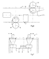
- Fig. 6 is a plan view of an embodiment of an orientation conveyor according to the invention.
- Fig. 7 is a side view of the embodiment of Fig. 6 .
- Fig. 8 is a plan view of an embodiment of a turning apparatus according to the invention.
- Fig. 9 is a side view of the embodiment of Fig. 8 .
- Figs. 1 and 2 show different views of an embodiment of the device 1 according to the invention.
- the device 1 is suitable for unloading the contents of a container 2.
- the container 2 may be used for containing luggage in aircrafts and may have a typical shape for fitting in an aircraft, as can be seen in Figs. 3a-3c .
- a lifting apparatus (not shown) of the device 1 lifts the container 2 to a higher height level and tilts the container 2 towards an opening 3 thereof.
- the opening 3 of the container 2 is located at one side of the container 2.
- the container 2 as well as the opening 3 may have different shapes as can be seen in Figs. 3a-3c . In the situation as shown in Fig.
- Fig. 3a shows an embodiment of a container 2 in which the opening 3 can be closed by a rigid but foldable closure 21. In an open condition the closure 21 opens the opening 3 at one side of the container 2 as well as a portion of the upper side of the container 2.
- the embodiment of Fig. 3b comprises a closure 21 which can be lifted and placed over the top of the container 2.
- the closure 21 may be a sheet, for example.
- Fig. 3c shows still another embodiment of the container 2, in which the closure 21 of the opening 3 can be moved and placed onto the top of the container 2.
- Figs. 1 and 2 illustrate a situation in which the container 2 is emptied almost entirely, but a single luggage piece 4 is retained. Such a piece 4 may be caught behind a rim 5 forming an edge of the opening 3, see Fig. 3 . Retained pieces 4 may be unloaded by a shaking mechanism.
- the device 1 according to the invention provides an alternative or additional solution for unloading retained pieces 4.
- the embodiment of the device 1 as shown in Figs. 1 and 2 comprises an arm 6 which functions as a discharge member.
- the arm 6 is rotatable about a pivoting axis 7. This means that it is movable with respect to the tilting apparatus.
- Fig. 1 shows two different positions of the arm 6.
- the arm 6 is rotatable such that an end portion of the arm 6 remote from the pivoting axis 7 can be moved into the container 2 through the opening 3 thereof when the container 2 is tilted by the tilting apparatus in the discharge condition thereof.
- the arm 6 in the embodiment as shown comprises two portions extending perpendicularly with respect to each other.
- the pivoting axis 7 of the arm 6 is located such that in the discharge condition of the tilting apparatus the pivoting axis 7 extends outside the container 2 and parallel to a tilting axis of the tilting apparatus. Due to the shape of the arm 6 an end portion of the arm 6 located remote from its pivoting axis 7 can be moved through the opening 3 into the container 2.
- a rotatable drum 8 is provided at the end portion of the arm 6 .
- the drum 8 is drivable in opposite directions.
- the drum 8 may be provided with protrusions projecting outwardly from the circumferential side thereof. It is noted that alternative embodiments of the arm 6 are conceivable.
- the arm 6 is movable parallel to the pivoting axis 7. This makes the device 1 more flexible to loosen caught luggage pieces 4 at different locations within the container 2.
- a second position of the drum 8 is illustrated by a broken line.
- the arm 6 including the drum 8 will be controlled by an operator via a joy stick (not shown).
- a closure 21 of the opening 3 of the container 2 is hold by a holding mechanism 9 as shown in Figs. 4 and 5 .
- the holding mechanism 9 comprises first holding elements 22 for holding a closure 21 in the form of a covering sheet, for example, by pressing it against the top of the container 2, and a second holding element 23 for holding a rigid foldable closure 21 in case of the embodiment of a container 2 as shown in Fig. 3a .
- the holding mechanism 9 is provided with pivots in order to be movable with respect to a supporting frame thereof, since the device 1 comprises a shaking mechanism (not shown) for shaking the container 2 so as to facilitate removing retained pieces 4 out of the container 2.
- Fig. 1 shows that under unloading conditions the articles 4 fall through the opening 3 of the container 2 onto a conveyor 10 for conveying the articles 4 further towards a desired destination.
- the articles 4 may have different sizes and different shapes, whereas they will have a random orientation on the conveyor 10.
- the device 1 according to the invention is provided with an orientation conveyor 11 for conveying and reorienting articles 4.
- An embodiment of the orientation conveyor 11 is shown in Figs. 6 and 7 .
- the embodiment of the orientation conveyor 11 comprises a drivable endless belt 12 including a supporting surface for supporting and transporting the articles 4 in a conveying direction X.
- rotation members in the form of a first drum 13 and a second drum 14 are located nearby the belt 12 and can be rotatably driven about rotation axes 15 as well as displaced transversely with respect to the conveying direction X.
- the first and second drums 13, 14 are spaced with respect to each other in the conveying direction X. In this case the rotation axes 15 extend vertically.
- Fig. 6 shows the first and second drums 13, 14 each in two different positions: a position above the belt 12 and a position next to the belt 12 as seen from above.
- an article 4 passes the first drum 13 and its orientation on the belt 12 as seen from above can be corrected by the first drum 13.
- the article 4 passes the second drum 14 which may correct the orientation of the article 4 on the belt 12 further.
- the first and second drums 13, 14 are controlled on the basis of information from a detection device (not shown) which is located upstream of the first drum 13. The detection device detects the orientation of the article 4 on the belt 12 before it arrives at the first drum 13.
- orientation conveyor 11 may be used as a separate apparatus for alternative devices, separate from the current device 1 including the tilting apparatus and the arm 6.
- the articles 4 may be treated such that they have a correct orientation on a conveyor, for example on the belt 12 as shown in Figs. 6 and 7 as seen from above, but it is still possible that an article 4 has wheels for easy moving the article 4 by a user, which wheels may be in contact with the driven conveyor belt 12. This may have disadvantageous effects during further transport by a conveyor. For example, at a transfer location where a successive conveyor belt runs upwardly the wheels may be driven by one of the conveyor belts at the transfer, whereas the article 4 stays at the same location. Therefore, the device 1 is provided with a turning apparatus 16 for turning articles 4 such that the wheels of an article 4 become free of contact with a conveyor belt, see Figs. 8 and 9 .
- the turning apparatus 16 comprises a first and second drivable conveyor belt 17, 18 as supporting surfaces for supporting and transporting the articles 4.
- the first and second, conveyor belt 17, 18 extend parallel to each other.
- the first conveyor belt 17 and the second conveyor belt 18 are mutually angled, in this case at an angle of substantially 90° about a longitudinal axis extending parallel to the belts 17, 18.
- Both conveyor belts 17, 18 are mounted to a frame 19 which is rotatable between a position which the first conveyor belt 17 is located lower than the second conveyor belt 13 and a position in which the second conveyor belt 18 is located lower than the first conveyor belt 17.
- the device 1 is further provided with a wheel detection device (not shown) which is located upstream of the turning apparatus 16. The wheel detection device detects whether a passing article 4 comprises wheels at the outer side thereof and, if so, the location of the wheels at the article 4 with respect to the upper surface of the first conveyor belt 17 or second conveyor belt 18, depending on which belt is located at a lower level.
- the article 4 When an article 4 of which the wheels are facing downwardly arrives at an input of the turning apparatus 16 on the first conveyor belt 17, the article 4 will be turned upside down by the turning apparatus 16 such that it will leave the turning apparatus 16 on the second conveyor belt 18. In that orientation the wheels of the article 4 will be free of the second conveyor 18, in this case facing upwardly.
- the turning apparatus 16 will be controlled by a control device (not shown) on the basis of information received from the wheel detection device.
- the frame 19 will maintain its position until an article 4 arrives at the input of the turning apparatus 16 whereas the wheels of the article 4 rest on the second conveyor belt 18, which is then located at a lower level than the first conveyor belt 17. Then the turning apparatus 16 will rotate back such that the second conveyor belt 18 goes up and the first conveyor belt 17 goes down.
- the article 4 turns upside down and leaves the turning apparatus 16 on the first conveyor belt 17 having its wheels facing upwardly. During the turning movement the first conveyor belt 17 and second conveyor belt 18 may still be driven.
- the frame 19 of the turning apparatus 16 rotates in opposite directions at an angle of about 90°
- a cam 20 which is located at a location where planes through the upper surfaces of the first conveyor belt 17 and the second conveyor belt 18 intersect.
- the cam 20 is adapted such that its width is smaller than the widths of the first and second conveyor belts 17, 18 and projects above the upper surfaces of the first conveyor belt 17, 18 as seen in cross section of the first conveyor belt 17 and the second conveyor belt 18, respectively.
- the width of the cam 20 is smaller than the dimensions of any side of the articles 4 since this improves the tilting movement of an article 4 touching the cam 20 when turning the frame 19.
- the invention provides a device for unloading the contents of a container which has optimal unloading characteristics
- the arm may have an alternative shape, for example telescopically driven.
Landscapes
- Engineering & Computer Science (AREA)
- Mechanical Engineering (AREA)
- Specific Conveyance Elements (AREA)
Priority Applications (1)
| Application Number | Priority Date | Filing Date | Title |
|---|---|---|---|
| EP20080170671 EP2194012B1 (fr) | 2008-12-04 | 2008-12-04 | Dispositif pour le déchargement de contenu d'un récipient |
Applications Claiming Priority (1)
| Application Number | Priority Date | Filing Date | Title |
|---|---|---|---|
| EP20080170671 EP2194012B1 (fr) | 2008-12-04 | 2008-12-04 | Dispositif pour le déchargement de contenu d'un récipient |
Publications (2)
| Publication Number | Publication Date |
|---|---|
| EP2194012A1 true EP2194012A1 (fr) | 2010-06-09 |
| EP2194012B1 EP2194012B1 (fr) | 2012-07-25 |
Family
ID=40336553
Family Applications (1)
| Application Number | Title | Priority Date | Filing Date |
|---|---|---|---|
| EP20080170671 Active EP2194012B1 (fr) | 2008-12-04 | 2008-12-04 | Dispositif pour le déchargement de contenu d'un récipient |
Country Status (1)
| Country | Link |
|---|---|
| EP (1) | EP2194012B1 (fr) |
Cited By (2)
| Publication number | Priority date | Publication date | Assignee | Title |
|---|---|---|---|---|
| CN113753579A (zh) * | 2021-09-22 | 2021-12-07 | 安徽巨一科技股份有限公司 | 一种智能物流自动输送线的倾斜装置 |
| CN113772403A (zh) * | 2020-07-27 | 2021-12-10 | 北京京东乾石科技有限公司 | 移除容器中物件的设备 |
Citations (11)
| Publication number | Priority date | Publication date | Assignee | Title |
|---|---|---|---|---|
| US4744715A (en) * | 1986-06-26 | 1988-05-17 | Fujitsu Limited | Wafer transfer apparatus |
| US5165520A (en) * | 1990-09-04 | 1992-11-24 | La Poste | Device for controlling and regularizing the spacing objects such as parcels, packages |
| US5261521A (en) * | 1990-07-12 | 1993-11-16 | Licentia Patent-Verwaltungs Gmbh | Apparatus for turning small goods, particularly packages, on a conveyor belt |
| EP0599228A2 (fr) * | 1992-11-20 | 1994-06-01 | Fuji Photo Film Co., Ltd. | Dispositifs pour convoyer et aligner des emballages de film photographique munis de lentilles |
| EP0704392A1 (fr) * | 1994-09-30 | 1996-04-03 | Jervis B. Webb International Company | Basculeur pour bagage à roulettes |
| DE19617413A1 (de) * | 1996-04-30 | 1997-11-06 | Homag Maschinenbau Ag | Vorrichtung zum Drehen eines Werkstückes |
| US6634846B1 (en) * | 1999-02-12 | 2003-10-21 | Siemens Aktiengesellschaft | Method and device for unloading a postal container that has an open top |
| US20050092580A1 (en) * | 2003-11-03 | 2005-05-05 | Clemens William J. | Conveyor belt transport alignment device, method and system |
| US20050281662A1 (en) * | 2004-06-22 | 2005-12-22 | Lockheed Martin Corporation | In-line flipper mechanism and conveyor system for achieving the proper orientation of mail tray and mail tub receptacles |
| NL1028666C2 (nl) | 2005-03-31 | 2006-10-03 | Ingbureaumoderniek B V | Inrichting voor het lossen van bagage. |
| US20080260506A1 (en) * | 2007-04-19 | 2008-10-23 | Siemens Aktiengesellschaft | Device for unloading a container |
-
2008
- 2008-12-04 EP EP20080170671 patent/EP2194012B1/fr active Active
Patent Citations (11)
| Publication number | Priority date | Publication date | Assignee | Title |
|---|---|---|---|---|
| US4744715A (en) * | 1986-06-26 | 1988-05-17 | Fujitsu Limited | Wafer transfer apparatus |
| US5261521A (en) * | 1990-07-12 | 1993-11-16 | Licentia Patent-Verwaltungs Gmbh | Apparatus for turning small goods, particularly packages, on a conveyor belt |
| US5165520A (en) * | 1990-09-04 | 1992-11-24 | La Poste | Device for controlling and regularizing the spacing objects such as parcels, packages |
| EP0599228A2 (fr) * | 1992-11-20 | 1994-06-01 | Fuji Photo Film Co., Ltd. | Dispositifs pour convoyer et aligner des emballages de film photographique munis de lentilles |
| EP0704392A1 (fr) * | 1994-09-30 | 1996-04-03 | Jervis B. Webb International Company | Basculeur pour bagage à roulettes |
| DE19617413A1 (de) * | 1996-04-30 | 1997-11-06 | Homag Maschinenbau Ag | Vorrichtung zum Drehen eines Werkstückes |
| US6634846B1 (en) * | 1999-02-12 | 2003-10-21 | Siemens Aktiengesellschaft | Method and device for unloading a postal container that has an open top |
| US20050092580A1 (en) * | 2003-11-03 | 2005-05-05 | Clemens William J. | Conveyor belt transport alignment device, method and system |
| US20050281662A1 (en) * | 2004-06-22 | 2005-12-22 | Lockheed Martin Corporation | In-line flipper mechanism and conveyor system for achieving the proper orientation of mail tray and mail tub receptacles |
| NL1028666C2 (nl) | 2005-03-31 | 2006-10-03 | Ingbureaumoderniek B V | Inrichting voor het lossen van bagage. |
| US20080260506A1 (en) * | 2007-04-19 | 2008-10-23 | Siemens Aktiengesellschaft | Device for unloading a container |
Cited By (3)
| Publication number | Priority date | Publication date | Assignee | Title |
|---|---|---|---|---|
| CN113772403A (zh) * | 2020-07-27 | 2021-12-10 | 北京京东乾石科技有限公司 | 移除容器中物件的设备 |
| CN113772403B (zh) * | 2020-07-27 | 2023-05-30 | 北京京东乾石科技有限公司 | 移除容器中物件的设备 |
| CN113753579A (zh) * | 2021-09-22 | 2021-12-07 | 安徽巨一科技股份有限公司 | 一种智能物流自动输送线的倾斜装置 |
Also Published As
| Publication number | Publication date |
|---|---|
| EP2194012B1 (fr) | 2012-07-25 |
Similar Documents
| Publication | Publication Date | Title |
|---|---|---|
| ES2996221T3 (en) | Unloading station and method for unloading a conveyed-goods container loaded with conveyed goods | |
| US4177621A (en) | Automatic fruit bagging | |
| CA2704106C (fr) | Procede et dispositif pour assurer la prehension et le transbordement de bagages | |
| US6726001B2 (en) | Transfer apparatus and method for film bags | |
| EP3556669B1 (fr) | Appareil de vidange de sacs | |
| CN107709201A (zh) | 行李处理系统 | |
| EP2194012A1 (fr) | Dispositif pour le déchargement de contenu d'un récipient, transporteur à orientation et appareil de tournage | |
| JP5531790B2 (ja) | 容器搬送装置 | |
| CN110282398B (zh) | 一种翻转式输送机 | |
| CN113242834A (zh) | 从侧向打开的大型货柜中卸载件货 | |
| NL2005406C2 (nl) | Producttransportinrichting voor het van een transportmiddel tillen van een product. | |
| DK3072838T3 (en) | DEVICE FOR LOADING BAGGAGE FROM A TRUCK AND PROCEDURE FOR OPERATING THE APPLIANCE | |
| KR101000432B1 (ko) | 과일 트레이 이송기의 과일 적재 트레이 정지 및 빈 트레이 자동반출방법 및 장치 | |
| DK2658798T3 (en) | TRANSPORTING DEVICE PROVIDED WITH A PORTABLE TRANSPORTATION TAPE AND METHOD OF USE | |
| JP2002154641A (ja) | 搬送物の反転装置 | |
| EP2019056B1 (fr) | Dispositif pour transporter des objets ronds | |
| CN108779610B (zh) | 用于装卸的方法和运输车辆 | |
| JP6753056B2 (ja) | 容器整列搬送装置 | |
| JP4840646B2 (ja) | 物品処理装置 | |
| JP6894353B2 (ja) | 物品送出しユニット | |
| JP2009120289A (ja) | 食品容器供給装置 | |
| CN114803545A (zh) | 小型零件的快速搬运装卸系统 | |
| JP3923384B2 (ja) | 折り畳まれた印刷製品を取り出すための排紙機 | |
| JPH077888U (ja) | 加工食材の把持装置 | |
| EP2208694B1 (fr) | Dispositif pour le transfert d'un container |
Legal Events
| Date | Code | Title | Description |
|---|---|---|---|
| PUAI | Public reference made under article 153(3) epc to a published international application that has entered the european phase |
Free format text: ORIGINAL CODE: 0009012 |
|
| AK | Designated contracting states |
Kind code of ref document: A1 Designated state(s): AT BE BG CH CY CZ DE DK EE ES FI FR GB GR HR HU IE IS IT LI LT LU LV MC MT NL NO PL PT RO SE SI SK TR |
|
| AX | Request for extension of the european patent |
Extension state: AL BA MK |
|
| 17P | Request for examination filed |
Effective date: 20101129 |
|
| AKX | Designation fees paid |
Designated state(s): AT BE BG CH CY CZ DE DK EE ES FI FR GB GR HR HU IE IS IT LI LT LU LV MC MT NL NO PL PT RO SE SI SK TR |
|
| 17Q | First examination report despatched |
Effective date: 20110722 |
|
| GRAP | Despatch of communication of intention to grant a patent |
Free format text: ORIGINAL CODE: EPIDOSNIGR1 |
|
| RTI1 | Title (correction) |
Free format text: A DEVICE FOR UNLOADING THE CONTENTS OF A CONTAINER, |
|
| GRAS | Grant fee paid |
Free format text: ORIGINAL CODE: EPIDOSNIGR3 |
|
| GRAA | (expected) grant |
Free format text: ORIGINAL CODE: 0009210 |
|
| AK | Designated contracting states |
Kind code of ref document: B1 Designated state(s): AT BE BG CH CY CZ DE DK EE ES FI FR GB GR HR HU IE IS IT LI LT LU LV MC MT NL NO PL PT RO SE SI SK TR |
|
| REG | Reference to a national code |
Ref country code: GB Ref legal event code: FG4D |
|
| REG | Reference to a national code |
Ref country code: CH Ref legal event code: EP |
|
| REG | Reference to a national code |
Ref country code: AT Ref legal event code: REF Ref document number: 567612 Country of ref document: AT Kind code of ref document: T Effective date: 20120815 Ref country code: IE Ref legal event code: FG4D |
|
| REG | Reference to a national code |
Ref country code: DE Ref legal event code: R096 Ref document number: 602008017380 Country of ref document: DE Effective date: 20120920 |
|
| REG | Reference to a national code |
Ref country code: NL Ref legal event code: VDEP Effective date: 20120725 |
|
| REG | Reference to a national code |
Ref country code: AT Ref legal event code: MK05 Ref document number: 567612 Country of ref document: AT Kind code of ref document: T Effective date: 20120725 |
|
| REG | Reference to a national code |
Ref country code: LT Ref legal event code: MG4D Effective date: 20120725 |
|
| PG25 | Lapsed in a contracting state [announced via postgrant information from national office to epo] |
Ref country code: AT Free format text: LAPSE BECAUSE OF FAILURE TO SUBMIT A TRANSLATION OF THE DESCRIPTION OR TO PAY THE FEE WITHIN THE PRESCRIBED TIME-LIMIT Effective date: 20120725 Ref country code: HR Free format text: LAPSE BECAUSE OF FAILURE TO SUBMIT A TRANSLATION OF THE DESCRIPTION OR TO PAY THE FEE WITHIN THE PRESCRIBED TIME-LIMIT Effective date: 20120725 Ref country code: BE Free format text: LAPSE BECAUSE OF FAILURE TO SUBMIT A TRANSLATION OF THE DESCRIPTION OR TO PAY THE FEE WITHIN THE PRESCRIBED TIME-LIMIT Effective date: 20120725 Ref country code: CY Free format text: LAPSE BECAUSE OF FAILURE TO SUBMIT A TRANSLATION OF THE DESCRIPTION OR TO PAY THE FEE WITHIN THE PRESCRIBED TIME-LIMIT Effective date: 20120725 Ref country code: IS Free format text: LAPSE BECAUSE OF FAILURE TO SUBMIT A TRANSLATION OF THE DESCRIPTION OR TO PAY THE FEE WITHIN THE PRESCRIBED TIME-LIMIT Effective date: 20121125 Ref country code: NO Free format text: LAPSE BECAUSE OF FAILURE TO SUBMIT A TRANSLATION OF THE DESCRIPTION OR TO PAY THE FEE WITHIN THE PRESCRIBED TIME-LIMIT Effective date: 20121025 Ref country code: FI Free format text: LAPSE BECAUSE OF FAILURE TO SUBMIT A TRANSLATION OF THE DESCRIPTION OR TO PAY THE FEE WITHIN THE PRESCRIBED TIME-LIMIT Effective date: 20120725 Ref country code: LT Free format text: LAPSE BECAUSE OF FAILURE TO SUBMIT A TRANSLATION OF THE DESCRIPTION OR TO PAY THE FEE WITHIN THE PRESCRIBED TIME-LIMIT Effective date: 20120725 |
|
| PG25 | Lapsed in a contracting state [announced via postgrant information from national office to epo] |
Ref country code: GR Free format text: LAPSE BECAUSE OF FAILURE TO SUBMIT A TRANSLATION OF THE DESCRIPTION OR TO PAY THE FEE WITHIN THE PRESCRIBED TIME-LIMIT Effective date: 20121026 Ref country code: LV Free format text: LAPSE BECAUSE OF FAILURE TO SUBMIT A TRANSLATION OF THE DESCRIPTION OR TO PAY THE FEE WITHIN THE PRESCRIBED TIME-LIMIT Effective date: 20120725 Ref country code: PT Free format text: LAPSE BECAUSE OF FAILURE TO SUBMIT A TRANSLATION OF THE DESCRIPTION OR TO PAY THE FEE WITHIN THE PRESCRIBED TIME-LIMIT Effective date: 20121126 Ref country code: SI Free format text: LAPSE BECAUSE OF FAILURE TO SUBMIT A TRANSLATION OF THE DESCRIPTION OR TO PAY THE FEE WITHIN THE PRESCRIBED TIME-LIMIT Effective date: 20120725 Ref country code: SE Free format text: LAPSE BECAUSE OF FAILURE TO SUBMIT A TRANSLATION OF THE DESCRIPTION OR TO PAY THE FEE WITHIN THE PRESCRIBED TIME-LIMIT Effective date: 20120725 Ref country code: PL Free format text: LAPSE BECAUSE OF FAILURE TO SUBMIT A TRANSLATION OF THE DESCRIPTION OR TO PAY THE FEE WITHIN THE PRESCRIBED TIME-LIMIT Effective date: 20120725 |
|
| PG25 | Lapsed in a contracting state [announced via postgrant information from national office to epo] |
Ref country code: NL Free format text: LAPSE BECAUSE OF FAILURE TO SUBMIT A TRANSLATION OF THE DESCRIPTION OR TO PAY THE FEE WITHIN THE PRESCRIBED TIME-LIMIT Effective date: 20120725 |
|
| PG25 | Lapsed in a contracting state [announced via postgrant information from national office to epo] |
Ref country code: CZ Free format text: LAPSE BECAUSE OF FAILURE TO SUBMIT A TRANSLATION OF THE DESCRIPTION OR TO PAY THE FEE WITHIN THE PRESCRIBED TIME-LIMIT Effective date: 20120725 Ref country code: ES Free format text: LAPSE BECAUSE OF FAILURE TO SUBMIT A TRANSLATION OF THE DESCRIPTION OR TO PAY THE FEE WITHIN THE PRESCRIBED TIME-LIMIT Effective date: 20121105 Ref country code: DK Free format text: LAPSE BECAUSE OF FAILURE TO SUBMIT A TRANSLATION OF THE DESCRIPTION OR TO PAY THE FEE WITHIN THE PRESCRIBED TIME-LIMIT Effective date: 20120725 Ref country code: EE Free format text: LAPSE BECAUSE OF FAILURE TO SUBMIT A TRANSLATION OF THE DESCRIPTION OR TO PAY THE FEE WITHIN THE PRESCRIBED TIME-LIMIT Effective date: 20120725 Ref country code: RO Free format text: LAPSE BECAUSE OF FAILURE TO SUBMIT A TRANSLATION OF THE DESCRIPTION OR TO PAY THE FEE WITHIN THE PRESCRIBED TIME-LIMIT Effective date: 20120725 |
|
| PG25 | Lapsed in a contracting state [announced via postgrant information from national office to epo] |
Ref country code: SK Free format text: LAPSE BECAUSE OF FAILURE TO SUBMIT A TRANSLATION OF THE DESCRIPTION OR TO PAY THE FEE WITHIN THE PRESCRIBED TIME-LIMIT Effective date: 20120725 Ref country code: IT Free format text: LAPSE BECAUSE OF FAILURE TO SUBMIT A TRANSLATION OF THE DESCRIPTION OR TO PAY THE FEE WITHIN THE PRESCRIBED TIME-LIMIT Effective date: 20120725 |
|
| PLBE | No opposition filed within time limit |
Free format text: ORIGINAL CODE: 0009261 |
|
| STAA | Information on the status of an ep patent application or granted ep patent |
Free format text: STATUS: NO OPPOSITION FILED WITHIN TIME LIMIT |
|
| 26N | No opposition filed |
Effective date: 20130426 |
|
| PG25 | Lapsed in a contracting state [announced via postgrant information from national office to epo] |
Ref country code: MC Free format text: LAPSE BECAUSE OF NON-PAYMENT OF DUE FEES Effective date: 20121231 Ref country code: BG Free format text: LAPSE BECAUSE OF FAILURE TO SUBMIT A TRANSLATION OF THE DESCRIPTION OR TO PAY THE FEE WITHIN THE PRESCRIBED TIME-LIMIT Effective date: 20121025 |
|
| REG | Reference to a national code |
Ref country code: CH Ref legal event code: PL |
|
| REG | Reference to a national code |
Ref country code: DE Ref legal event code: R097 Ref document number: 602008017380 Country of ref document: DE Effective date: 20130426 |
|
| GBPC | Gb: european patent ceased through non-payment of renewal fee |
Effective date: 20121204 |
|
| REG | Reference to a national code |
Ref country code: IE Ref legal event code: MM4A |
|
| PG25 | Lapsed in a contracting state [announced via postgrant information from national office to epo] |
Ref country code: LI Free format text: LAPSE BECAUSE OF NON-PAYMENT OF DUE FEES Effective date: 20121231 Ref country code: IE Free format text: LAPSE BECAUSE OF NON-PAYMENT OF DUE FEES Effective date: 20121204 Ref country code: CH Free format text: LAPSE BECAUSE OF NON-PAYMENT OF DUE FEES Effective date: 20121231 |
|
| PG25 | Lapsed in a contracting state [announced via postgrant information from national office to epo] |
Ref country code: MT Free format text: LAPSE BECAUSE OF FAILURE TO SUBMIT A TRANSLATION OF THE DESCRIPTION OR TO PAY THE FEE WITHIN THE PRESCRIBED TIME-LIMIT Effective date: 20120725 Ref country code: GB Free format text: LAPSE BECAUSE OF NON-PAYMENT OF DUE FEES Effective date: 20121204 |
|
| PG25 | Lapsed in a contracting state [announced via postgrant information from national office to epo] |
Ref country code: TR Free format text: LAPSE BECAUSE OF FAILURE TO SUBMIT A TRANSLATION OF THE DESCRIPTION OR TO PAY THE FEE WITHIN THE PRESCRIBED TIME-LIMIT Effective date: 20120725 |
|
| PG25 | Lapsed in a contracting state [announced via postgrant information from national office to epo] |
Ref country code: LU Free format text: LAPSE BECAUSE OF NON-PAYMENT OF DUE FEES Effective date: 20121204 |
|
| PG25 | Lapsed in a contracting state [announced via postgrant information from national office to epo] |
Ref country code: HU Free format text: LAPSE BECAUSE OF FAILURE TO SUBMIT A TRANSLATION OF THE DESCRIPTION OR TO PAY THE FEE WITHIN THE PRESCRIBED TIME-LIMIT Effective date: 20081204 |
|
| REG | Reference to a national code |
Ref country code: FR Ref legal event code: PLFP Year of fee payment: 8 |
|
| REG | Reference to a national code |
Ref country code: FR Ref legal event code: PLFP Year of fee payment: 9 |
|
| REG | Reference to a national code |
Ref country code: FR Ref legal event code: PLFP Year of fee payment: 10 |
|
| PGFP | Annual fee paid to national office [announced via postgrant information from national office to epo] |
Ref country code: FR Payment date: 20251226 Year of fee payment: 18 |
|
| PGFP | Annual fee paid to national office [announced via postgrant information from national office to epo] |
Ref country code: DE Payment date: 20251229 Year of fee payment: 18 |