EP2194166A1 - Quarzglastiegel, verfahren zu seiner herstellung und züchtungsverfahren - Google Patents
Quarzglastiegel, verfahren zu seiner herstellung und züchtungsverfahren Download PDFInfo
- Publication number
- EP2194166A1 EP2194166A1 EP08825826A EP08825826A EP2194166A1 EP 2194166 A1 EP2194166 A1 EP 2194166A1 EP 08825826 A EP08825826 A EP 08825826A EP 08825826 A EP08825826 A EP 08825826A EP 2194166 A1 EP2194166 A1 EP 2194166A1
- Authority
- EP
- European Patent Office
- Prior art keywords
- layer
- silica glass
- bubble
- surface layer
- crucible
- Prior art date
- Legal status (The legal status is an assumption and is not a legal conclusion. Google has not performed a legal analysis and makes no representation as to the accuracy of the status listed.)
- Withdrawn
Links
Images




Classifications
-
- C—CHEMISTRY; METALLURGY
- C03—GLASS; MINERAL OR SLAG WOOL
- C03B—MANUFACTURE, SHAPING, OR SUPPLEMENTARY PROCESSES
- C03B19/00—Other methods of shaping glass
- C03B19/09—Other methods of shaping glass by fusing powdered glass in a shaping mould
- C03B19/095—Other methods of shaping glass by fusing powdered glass in a shaping mould by centrifuging, e.g. arc discharge in rotating mould
-
- C—CHEMISTRY; METALLURGY
- C03—GLASS; MINERAL OR SLAG WOOL
- C03B—MANUFACTURE, SHAPING, OR SUPPLEMENTARY PROCESSES
- C03B20/00—Processes specially adapted for the production of quartz or fused silica articles, not otherwise provided for
-
- C—CHEMISTRY; METALLURGY
- C30—CRYSTAL GROWTH
- C30B—SINGLE-CRYSTAL GROWTH; UNIDIRECTIONAL SOLIDIFICATION OF EUTECTIC MATERIAL OR UNIDIRECTIONAL DEMIXING OF EUTECTOID MATERIAL; REFINING BY ZONE-MELTING OF MATERIAL; PRODUCTION OF A HOMOGENEOUS POLYCRYSTALLINE MATERIAL WITH DEFINED STRUCTURE; SINGLE CRYSTALS OR HOMOGENEOUS POLYCRYSTALLINE MATERIAL WITH DEFINED STRUCTURE; AFTER-TREATMENT OF SINGLE CRYSTALS OR A HOMOGENEOUS POLYCRYSTALLINE MATERIAL WITH DEFINED STRUCTURE; APPARATUS THEREFOR
- C30B15/00—Single-crystal growth by pulling from a melt, e.g. Czochralski method
- C30B15/10—Crucibles or containers for supporting the melt
-
- C—CHEMISTRY; METALLURGY
- C30—CRYSTAL GROWTH
- C30B—SINGLE-CRYSTAL GROWTH; UNIDIRECTIONAL SOLIDIFICATION OF EUTECTIC MATERIAL OR UNIDIRECTIONAL DEMIXING OF EUTECTOID MATERIAL; REFINING BY ZONE-MELTING OF MATERIAL; PRODUCTION OF A HOMOGENEOUS POLYCRYSTALLINE MATERIAL WITH DEFINED STRUCTURE; SINGLE CRYSTALS OR HOMOGENEOUS POLYCRYSTALLINE MATERIAL WITH DEFINED STRUCTURE; AFTER-TREATMENT OF SINGLE CRYSTALS OR A HOMOGENEOUS POLYCRYSTALLINE MATERIAL WITH DEFINED STRUCTURE; APPARATUS THEREFOR
- C30B29/00—Single crystals or homogeneous polycrystalline material with defined structure characterised by the material or by their shape
- C30B29/02—Elements
- C30B29/06—Silicon
-
- C—CHEMISTRY; METALLURGY
- C30—CRYSTAL GROWTH
- C30B—SINGLE-CRYSTAL GROWTH; UNIDIRECTIONAL SOLIDIFICATION OF EUTECTIC MATERIAL OR UNIDIRECTIONAL DEMIXING OF EUTECTOID MATERIAL; REFINING BY ZONE-MELTING OF MATERIAL; PRODUCTION OF A HOMOGENEOUS POLYCRYSTALLINE MATERIAL WITH DEFINED STRUCTURE; SINGLE CRYSTALS OR HOMOGENEOUS POLYCRYSTALLINE MATERIAL WITH DEFINED STRUCTURE; AFTER-TREATMENT OF SINGLE CRYSTALS OR A HOMOGENEOUS POLYCRYSTALLINE MATERIAL WITH DEFINED STRUCTURE; APPARATUS THEREFOR
- C30B35/00—Apparatus not otherwise provided for, specially adapted for the growth, production or after-treatment of single crystals or of a homogeneous polycrystalline material with defined structure
- C30B35/002—Crucibles or containers
-
- Y—GENERAL TAGGING OF NEW TECHNOLOGICAL DEVELOPMENTS; GENERAL TAGGING OF CROSS-SECTIONAL TECHNOLOGIES SPANNING OVER SEVERAL SECTIONS OF THE IPC; TECHNICAL SUBJECTS COVERED BY FORMER USPC CROSS-REFERENCE ART COLLECTIONS [XRACs] AND DIGESTS
- Y10—TECHNICAL SUBJECTS COVERED BY FORMER USPC
- Y10T—TECHNICAL SUBJECTS COVERED BY FORMER US CLASSIFICATION
- Y10T117/00—Single-crystal, oriented-crystal, and epitaxy growth processes; non-coating apparatus therefor
- Y10T117/10—Apparatus
- Y10T117/1024—Apparatus for crystallization from liquid or supercritical state
Definitions
- the present invention relates to a silica glass crucible having an excellent heat conducting effect and uniform heat conductivity, and a method of manufacturing the same, as well as an application thereof.
- Priority is claimed on Japanese Patent Application No. 2007-256155, filed September 28, 2007 , the content of which is incorporated herein by reference.
- a silica glass crucible to be filled with a silicon melt is used for pulling single-crystal silicon.
- the inner surface of this silica glass crucible is formed of a transparent glass layer including substantially no bubbles because it has to be in contact with a silicon melt, and the outer surface thereof is formed of a bubble-containing layer including a number of bubbles so as to uniformly transfer heat from the outer part to the inside of a mold.
- a rotary mold method is conventionally known as a method of manufacturing the above-mentioned silica glass crucible.
- This is a method of manufacturing a crucible by heating a quartz powder accumulated on the inner surface of a rotary mold from a space side of the mold for vitrification, wherein during this heating and melting, evacuation is performed to remove bubbles in a glass layer by sucking air in the quartz powder-deposited layer from the mold side to reduce the pressure thereby forming on the inner surface of the crucible a transparent glass layer containing substantially no bubbles ( JP-ANo. H02-055285 and JP-A No. H10-017391 ).
- a spraying method is known as a method of manufacturing the silica glass crucible. This is a method of manufacturing a silica glass crucible by spraying molten quartz onto an inner surface of the mold ( JP-A No. H01-148718 and JP-A No. H01-148782 ).
- the existing silica glass crucible manufactured by any of a rotary mold method and a spraying method, which is used for pulling single-crystal silicon has a two-layer constitution including a transparent glass layer in the inner side and a bubble-containing layer in the outer side.
- a crucible having such a constitution heat from the heated outer part is dispersed by the bubble-containing layer of the outer surface, and thus a silicon melt can be prevented from being locally heated, thereby hardly causing temperature irregularity in the silicon melt.
- the transparent glass layer of the inner surface contains substantially no bubbles, a separation bubble does not occur and thus there is an advantage of reducing the dislocation content upon pulling single-crystal silicon.
- the present invention has solved the problems in a known silica glass crucible, which provides a silica glass crucible capable of sufficiently dispersing heat from the external radiation thereby preventing temperature irregularity in the silicon melt, and at the same time, exhibiting excellent heat conductivity thereby giving a uniformly heated state over a wide range in the entire crucible without taking a long time for increasing the temperature to form a silicon melt, which also provides a manufacturing method thereof.
- the invention relates to a silicon glass crucible which has solved the above-mentioned problems by employing the following constitutions shown in [1] to [3].
- the invention relates to a method of manufacturing a silica glass crucible and a pulling method which have solved the above-mentioned problems by employing the following constitutions shown in [4] to [7].
- a method of manufacturing a silica glass crucible including heating and melting a quartz powder accumulated on the inner surface of a rotary mold from a space side of the mold, where upon the heating and melting, evacuation is performed to remove bubbles by sucking air in the quartz powder-deposited layer from the mold side, the method being characterized by intermittently performing evacuation and leakage to form a laminated layer of bubble-containing layers and transparent glass layers between the outer surface layer and the inner surface layer.
- the silica glass crucible of the invention includes between the outer surface layer and the inner surface layer an intermediate layer in which bubble-containing layers and transparent glass layers are laminated, and thus heat from the external radiation is dispersed by the bubble-containing layers thereby conducting heat over a wide range. Consequently, the temperature distribution of a silica glass interface of the crucible which comes into contact with a silicon melt becomes uniform over a wide range and thus the silicon melt is uniformly heated. Therefore, temperature irregularity in the silicon melt does not occur. Moreover, since a transparent glass layer is constituted in addition to the bubble-containing layer, heat dispersed by the bubble-containing layers is efficiently transferred via the transparent glass layer, and thus the property of conducting heat from the high-temperature radiation is significantly improved.
- the silica glass crucible of the invention is not provided with a locally hot area heated by external radiation, and furthermore, the invention provides temperature uniformity in the silica glass interface at low temperature as compared to the known two-layer structured silica glass crucible. Therefore, vibration of the melt surface caused by a SiO gas generation is not generated upon pulling single-crystal silicon.
- the silica glass crucible of the invention can be manufactured by intermittently performing evacuation and leakage processes in the method of manufacturing a silica glass crucible according to a rotary mold method. Also, an intermediate layer in which the plurality of bubble-containing layers and transparent glass layers are laminated can be formed by intermittently performing evacuation and leakage.
- the laminated structure of the bubble-containing layers and the transparent glass layers of the invention is formed by alternately performing an operation of keeping the area around a quartz powder of a molten part vacuous when the quartz powder is in a molten state, and an operation of leakage. That is, this structure cannot be formed by the known spraying method wherein evacuation and leakage are not performed.
- helium gas which has high heat conductivity, is used as the leak gas upon repeatedly performing intermittent evacuation and leakage. Accordingly, the effect of increasing the temperature by external heating is improved significantly thereby promoting the uniform heating of a silica glass interface.
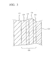
- an outer surface layer C1 is formed of a bubble-containing silica glass layer and an inner surface layer C2 is formed of a silica glass layer whose bubbles are invisible to the naked eye.
- an intermediate layer C5 in which a bubble-containing silica glass layer (bubble-containing layer) including bubbles with a diameter of 100 ⁇ m or smaller by 0.1% or more in the volumetric bubble content and a silica glass layer (transparent glass layer) including the bubbles by 0.05% or less in the volumetric bubble content are laminated, is interposed between the outer surface layer C1 and the inner surface layer C2.
- the silica glass crucible C of the invention includes the outer surface layer C1 (outer side bubble-containing layer) formed of a bubble-containing silica glass layer and the inner surface layer C2 (bubble-free transparent glass layer) formed of a silica glass layer whose bubbles are invisible to the naked eye, and the intermediate layer C5 is interposed between the outer surface layer C 1 and the inner surface layer C2.
- the intermediate layer C5 is formed of the bubble-containing layer C3 and the transparent glass layer C4.
- the bubble quantity and the layer thickness for the bubble-containing silica glass layer of the outer surface layer C1 are not particularly limited and may be the same as those for the outer surface layer of the known silica glass crucible.
- the inner surface layer C2 is formed of a silica glass layer (bubble-free transparent glass layer) whose bubbles are invisible to the naked eye, and the layer thickness thereof is greater than the thickness that erodes by the silicon melt.
- the bubble-containing layer C3 constituting the intermediate layer C5 contains bubbles having a diameter of 100 ⁇ m or less by 0.1% or more in a volumetric bubble content, and it is a silica glass layer having a layer thickness of preferably 0.5 mm or more, more preferably 0.5 to 4 mm.
- the bubble content in the bubble-containing layer C3 is less than 0.1 %, heat from the radiation outside cannot be sufficiently dispersed, thus it is not preferable.
- a diameter of the bubbles in the bubble-containing layer is larger than 100 ⁇ m, the bubble diameter becomes substantially large during the use under high temperature for pulling because of the bubble expansion, which then lowers the effect of uniform heat dispersion thereby causing irregularity in the inner surface temperature of the crucible, thus it is not preferable.
- the layer thickness of the bubble-containing layer C3 is less than 0.5 mm, heat radiation from outside cannot be sufficiently dispersed, thus it is not preferable. Meanwhile, when the layer thickness of the bubble-containing layer C3 is too great, the heat conducting effect is lowered and a longer time to increase the temperature when forming a silicon melt will be required, and also temperature irregularity after melting readily occurs due to the low heat transfer. Therefore, the layer thickness of the bubble-containing layer C3 is preferably from 0.5 to 4 mm.
- the transparent glass layer C4 constituting the intermediate layer C5 is a silica glass layer having a volumetric bubble content of 0.05% or less and layer thickness of preferably 0.5 to 4 mm.
- the bubble content of the transparent glass layer is larger than 0.05%, its transparency deteriorates and the effect of transferring the heat from the external radiation is lowered, thus it is not preferable.
- the layer thickness of the transparent glass layer C4 is less than 0.5 mm, the effect of increasing the heat transfer by the transparent glass layer becomes insufficient. Meanwhile, when the layer thickness is greater than 4 mm, heat that escapes from the upper-edge rim of the crucible C becomes too significant thereby giving poor heat efficiency, thus it is not preferable.
- the intermediate layer C5 interposed between the outer surface layer C1 and the inner surface layer C2 may be constituted by laminating the plurality of bubble-containing layers C3 and transparent glass layers C4 in an alternate manner.
- the bubble-containing layer C3 and the transparent glass layer C4 are alternately laminated, and this combination of bubble-containing layer C3 and transparent glass layer C4 is formed twice thereby giving two laminations, but the number of laminations including a combination of the bubble-containing layer C3 and the transparent glass layer C4 is not limited.
- the bubble-containing layer C3 is formed on the inner surface layer side and the transparent glass layer C4 is formed on the outer surface side, but the order of the lamination for the intermediate layer C5 is not limited thereto.
- the silica glass crucible C of the invention can be manufactured by using a manufacturing device of a silica glass crucible shown in FIG. 4 .
- the silica glass crucible manufacturing device 1 is roughly constituted by, as shown in FIG. 4 , a mold 10 which has a melting space in the inner part for melting a quartz powder and forming a quartz glass crucible, a driving mechanism not shown in the figure which rotates the mold 10 round the axis, and a plurality of carbon electrodes 13 which acts as an arc discharge means for heating the inner side of the mold 10.
- the mold 10 is formed of, for example, carbon, and a number of pressure-reducing passages 12 which are open to the surface of inner part of the mold 10 are formed in the inside, as shown in FIG. 4 .
- the pressure-reducing passage 12 is connected with a pressure-reducing mechanism 51 which thus allows a suction of air from the inner surface of the mold 10 via the pressure-reducing passage 12 at the time of rotating the mold 10.
- the pressure-reducing mechanism 51 and the arc discharge means are connected with a control means 50, and they are controlled by this control means 50.
- the pressure-reducing means 51 is capable of switching over between an evacuation (reducing pressure) state and a leakage (introducing a leak gas to the mold side) state.
- a plurality of electrodes 13 is provided as the arc discharge means at the upper side of the mold 10 in the silica glass crucible manufacturing device 1.
- the electrode 13 is formed in a combination of three electrodes.
- the electrodes 13 are each fixed to a support 22 at the upper part of a furnace, and the support 22 is provided with a means (omitted in the figure) to vertically move the electrode 21.
- the support 22 is provided with a supporting part 21 that supports the carbon electrode 13 while allowing setting of the distance between the electrodes, a horizontally transferring means that allows the supporting part 21 to move in a horizontal direction, and a vertically transferring means that allows the plurality of supporting parts 21 and the respective horizontally transferring means to move integrally in a vertical direction.
- the supporting part 21 does the supporting by allowing the carbon electrode 13 to move round an angle setting axis 22, and is provided with a rotation means that controls the rotation angle of the angle setting axis 22.
- the angle of the carbon electrode 13 is controlled by the rotation means, as well as the horizontal position of the supporting part 21 being controlled by the horizontally transferring means and the height of the supporting part 21 is also controlled by the vertical transferring means.
- the supporting part 21 and the like are shown in only the left end of the carbon electrode 13 in the figure, but other electrodes are also supported by the same constitution and the height of each carbon electrode 13 can be controlled individually.
- a rotary mold method with the use of the quartz glass crucible manufacturing device 1 is employed for the production, and a quartz-powder filling step, an arc melting step, a cooling step, a taking-out step, a honing processing step, a rim cutting step and a washing step are included for the production.
- a quartz-powder filling step a quartz-powder layer 11 is formed by depositing a quartz raw powder on the inner surface of the mold 10. This quartz-powder layer 11 is held on the inner-wall surface by the centrifugal force from the rotation of the mold 10.
- a position of the electrode 13 is arranged, and a pressure is reduced and a leak gas is introduced through the pressure-reducing passage 12 while heating the left quartz-powder layer 11 with the arc discharge means, thereby melting the quartz-powder layer 11 to form a quartz glass layer.
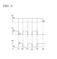
- a quartz powder accumulated on the inner surface of the rotary mold is heated from the mold space side so as to be melted, and when performing an evacuation to remove bubbles by sucking air in the quartz powder-deposited layer from the mold side during the heating and melting, evacuation and leakage are intermittently performed as shown in FIG. 5 and FIG. 6 for the production.
- an intermediate layer in which the plurality of bubble-containing layers and transparent glass layers are laminated in the alternate manner can be formed between the outer surface layer and the inner surface layer by intermittently performing evacuation and leakage several times.
- a mixed gas containing 50% or more of helium gas As the leak gas.
- helium gas is included as the gas ingredient for gas in bubbles of the bubble-containing layer, the heat conducting effect can be improved further.
- the concentration of helium gas in a mixed gas to be introduced is preferably 50% or more. At a helium gas concentration of less than 50%, the effect to be achieved by introducing the helium gas will be lowered.
- the invention includes a method of manufacturing single-crystal silicon, which includes a step of melting polycrystal silicon in a crucible and a step of pulling a single-crystal silicon ingot by immersing a seed of single-crystal silicon in the molten silicon melt.
- FIG. 7 is a longitudinal cross-sectional view showing a state in which a single-crystal silicon ingot I is pulled out from a silicon melt Y in a silica glass crucible C.
- a silica powder was accumulated to a thickness of 30 mm on the inner side of a rotary mold having an inner diameter of ⁇ 630 mm, and the accumulated silica powder was heated from a space side of the mold at 2200°C for arc melting.
- evacuation was performed from a rotary mold side to form a transparent inner surface layer.
- evacuation was released and air leakage was allowed for 60 seconds, and thereafter, evacuation was again performed from the mold side for 60 seconds.
- These leakage and evacuation were, each at 60-second intervals, sequentially carried out three times to form an intermediate layer.
- the arc melting was continued for a predetermined period under an air leakage state to form an outer surface layer.
- silica glass crucible In the production of a silica glass crucible by depositing a silica powder on the inner side of a rotary mold according to the same method as in Example 1, after forming a transparent inner surface layer, air was allowed to leak for 120 seconds followed by evacuation for 60 seconds, and this pattern was repeated twice. Thereafter, the arc melting was continued for a predetermined period under an air leakage state to form an outer surface layer. A cross section of this silica glass crucible was observed.
- this crucible was used for pulling single-crystal silicon as in Example 1, the time required for increasing the temperature when forming a silicon melt was shortened by approximately 12% as compared to the case where the known two-layered silica glass crucible was used, and the temperature of the crucible was lowered by 3°C. In addition, vibration of the melt surface was not observed upon pulling.
- silica glass crucible In the production of a silica glass crucible by depositing a silica powder on the inner side of a rotary mold according to the same method as in Example 1, after forming a transparent inner surface layer, without alternately performing the evacuation and leakage, arc melting was performed for a predetermined period while allowing the air leakage to produce a silica glass crucible.
- the silica glass crucible had a two-layered structure (including no intermediate layer) in which an outer surface layer (bubble-containing outer side layer) of about 7 mm is formed on the outer side of an inner surface layer (bubble-free transparent glass layer) of about 3 mm.
- this crucible was used as a vessel for pulling single-crystal silicon, violent vibration was observed upon pulling.
- the intermediate layer in which bubble-containing layers and transparent glass layers are laminated is interposed between an outer surface layer and an inner surface layer, heat from an external radiation is dispersed by the bubble-containing layer to transfer heat over a wide range, and accordingly the temperature distribution of a silica glass interface of the crucible coming in contact with a silicon melt becomes uniform over a wide range thereby uniformly heating the silicon melt. Thus, temperature irregularity in the silicon melt does not occur.
- the transparent glass layers are constituted in addition to the bubble-containing layers, heat dispersed by the bubble-containing layers is efficiently transferred through the transparent glass layer, and thus the property of conducting heat from the high-temperature radiation is significantly improved.
- the silica glass crucible can be manufactured by intermittently performing evacuation and leakage in the method of manufacturing a silica glass crucible according to a rotary mold method. Also, an intermediate layer in which the plurality of bubble-containing layers and transparent glass layers are laminated can be formed by intermittently performing evacuation and leakage.
Landscapes
- Chemical & Material Sciences (AREA)
- Engineering & Computer Science (AREA)
- Materials Engineering (AREA)
- Organic Chemistry (AREA)
- Crystallography & Structural Chemistry (AREA)
- Metallurgy (AREA)
- Manufacturing & Machinery (AREA)
- Crystals, And After-Treatments Of Crystals (AREA)
- Glass Melting And Manufacturing (AREA)
Applications Claiming Priority (2)
| Application Number | Priority Date | Filing Date | Title |
|---|---|---|---|
| JP2007256155A JP5143520B2 (ja) | 2007-09-28 | 2007-09-28 | シリカガラスルツボとその製造方法および引き上げ方法 |
| PCT/JP2008/067651 WO2009041684A1 (ja) | 2007-09-28 | 2008-09-29 | シリカガラスルツボとその製造方法および引き上げ方法 |
Publications (2)
| Publication Number | Publication Date |
|---|---|
| EP2194166A1 true EP2194166A1 (de) | 2010-06-09 |
| EP2194166A4 EP2194166A4 (de) | 2014-05-21 |
Family
ID=40511562
Family Applications (1)
| Application Number | Title | Priority Date | Filing Date |
|---|---|---|---|
| EP08825826.4A Withdrawn EP2194166A4 (de) | 2007-09-28 | 2008-09-29 | Quarzglastiegel, verfahren zu seiner herstellung und züchtungsverfahren |
Country Status (6)
| Country | Link |
|---|---|
| US (1) | US20100319608A1 (de) |
| EP (1) | EP2194166A4 (de) |
| JP (1) | JP5143520B2 (de) |
| KR (1) | KR20100066252A (de) |
| TW (1) | TWI383962B (de) |
| WO (1) | WO2009041684A1 (de) |
Families Citing this family (16)
| Publication number | Priority date | Publication date | Assignee | Title |
|---|---|---|---|---|
| US7496695B2 (en) | 2005-09-29 | 2009-02-24 | P.A. Semi, Inc. | Unified DMA |
| US8272234B2 (en) | 2008-12-19 | 2012-09-25 | Heraeus Shin-Etsu America, Inc. | Silica crucible with pure and bubble free inner crucible layer and method of making the same |
| CN102395535B (zh) * | 2009-05-26 | 2014-07-02 | 信越石英株式会社 | 二氧化硅容器及其制造方法 |
| JP4922355B2 (ja) * | 2009-07-15 | 2012-04-25 | 信越石英株式会社 | シリカ容器及びその製造方法 |
| US9133063B2 (en) * | 2009-09-09 | 2015-09-15 | Sumco Corporation | Composite crucible, method of manufacturing the same, and method of manufacturing silicon crystal |
| JP5334314B2 (ja) * | 2009-09-30 | 2013-11-06 | コバレントマテリアル株式会社 | シリコン単結晶引上げ用シリカガラスルツボ |
| JP5397857B2 (ja) * | 2009-10-20 | 2014-01-22 | 株式会社Sumco | 石英ガラスルツボの製造方法および製造装置 |
| US9003832B2 (en) | 2009-11-20 | 2015-04-14 | Heraeus Shin-Etsu America, Inc. | Method of making a silica crucible in a controlled atmosphere |
| JP5500684B2 (ja) * | 2010-06-25 | 2014-05-21 | 株式会社Sumco | シリカガラスルツボ及びその製造方法、シリコンインゴットの製造方法 |
| JP5605902B2 (ja) * | 2010-12-01 | 2014-10-15 | 株式会社Sumco | シリカガラスルツボの製造方法、シリカガラスルツボ |
| JP5618409B2 (ja) * | 2010-12-01 | 2014-11-05 | 株式会社Sumco | シリカガラスルツボ |
| JP5500688B2 (ja) * | 2010-12-03 | 2014-05-21 | 株式会社Sumco | シリカガラスルツボの製造方法 |
| JP7157932B2 (ja) * | 2019-01-11 | 2022-10-21 | 株式会社Sumco | シリカガラスルツボの製造装置および製造方法 |
| JP7369573B2 (ja) * | 2019-09-13 | 2023-10-26 | 信越石英株式会社 | 反射部材及びガラス積層部材の製造方法 |
| JP7341017B2 (ja) * | 2019-09-30 | 2023-09-08 | 信越石英株式会社 | 熱反射部材及び熱反射層付きガラス部材の製造方法 |
| JP7673758B2 (ja) * | 2020-12-18 | 2025-05-09 | 株式会社Sumco | 石英ガラスルツボ及びその製造方法並びにシリコン単結晶の製造方法 |
Family Cites Families (11)
| Publication number | Priority date | Publication date | Assignee | Title |
|---|---|---|---|---|
| US4935046A (en) * | 1987-12-03 | 1990-06-19 | Shin-Etsu Handotai Company, Limited | Manufacture of a quartz glass vessel for the growth of single crystal semiconductor |
| JP2001122688A (ja) * | 1999-10-27 | 2001-05-08 | Nanwa Kuorutsu:Kk | 石英ガラスるつぼ |
| JP4447738B2 (ja) * | 2000-05-31 | 2010-04-07 | 信越石英株式会社 | 多層構造の石英ガラスルツボの製造方法 |
| DE10041582B4 (de) * | 2000-08-24 | 2007-01-18 | Heraeus Quarzglas Gmbh & Co. Kg | Quarzglastiegel sowie Verfahren zur Herstellung desselben |
| US6510707B2 (en) * | 2001-03-15 | 2003-01-28 | Heraeus Shin-Etsu America, Inc. | Methods for making silica crucibles |
| JP4841764B2 (ja) * | 2001-07-23 | 2011-12-21 | 信越石英株式会社 | シリコン単結晶引上げ用石英ガラスるつぼの製造方法及び装置 |
| KR100718314B1 (ko) * | 2003-05-01 | 2007-05-15 | 신에쯔 세끼에이 가부시키가이샤 | 실리콘 단결정 인상용 석영유리 도가니 및 그 제조방법 |
| JP4358555B2 (ja) * | 2003-05-30 | 2009-11-04 | ジャパンスーパークォーツ株式会社 | シリコン単結晶引上用石英ガラスルツボとその引上方法 |
| JP4726436B2 (ja) * | 2004-05-31 | 2011-07-20 | ジャパンスーパークォーツ株式会社 | 石英ガラスルツボの製造方法 |
| JP4789437B2 (ja) * | 2004-07-16 | 2011-10-12 | 信越石英株式会社 | シリコン単結晶引上げ用石英ガラスるつぼおよびその製造方法 |
| KR100847500B1 (ko) * | 2006-03-30 | 2008-07-22 | 코바렌트 마테리얼 가부시키가이샤 | 실리카 유리 도가니 |
-
2007
- 2007-09-28 JP JP2007256155A patent/JP5143520B2/ja active Active
-
2008
- 2008-09-29 WO PCT/JP2008/067651 patent/WO2009041684A1/ja not_active Ceased
- 2008-09-29 KR KR1020087029176A patent/KR20100066252A/ko not_active Ceased
- 2008-09-29 US US12/303,139 patent/US20100319608A1/en not_active Abandoned
- 2008-09-29 EP EP08825826.4A patent/EP2194166A4/de not_active Withdrawn
- 2008-09-30 TW TW097137541A patent/TWI383962B/zh not_active IP Right Cessation
Also Published As
| Publication number | Publication date |
|---|---|
| TW200922890A (en) | 2009-06-01 |
| TWI383962B (zh) | 2013-02-01 |
| US20100319608A1 (en) | 2010-12-23 |
| KR20100066252A (ko) | 2010-06-17 |
| JP2009084113A (ja) | 2009-04-23 |
| EP2194166A4 (de) | 2014-05-21 |
| JP5143520B2 (ja) | 2013-02-13 |
| WO2009041684A1 (ja) | 2009-04-02 |
Similar Documents
| Publication | Publication Date | Title |
|---|---|---|
| EP2194166A1 (de) | Quarzglastiegel, verfahren zu seiner herstellung und züchtungsverfahren | |
| CN104150755B (zh) | 一种重复多次拉制单晶硅用石英坩埚及其制造方法 | |
| EP2202335B1 (de) | Quarzglastiegel für die züchtung von siliziumeinkristallen und verfahren zur herstellung des tiegels | |
| US8888915B2 (en) | High-purity vitreous silica crucible used for pulling large-diameter single-crystal silicon ingot | |
| JP2020105071A (ja) | 石英ガラスルツボ | |
| EP2397582A1 (de) | Quarzglastiegel für die züchtung von monokristallinem silizium und verfahren zur herstellung von monokristallinem silizium | |
| JP4789437B2 (ja) | シリコン単結晶引上げ用石英ガラスるつぼおよびその製造方法 | |
| JP2007169145A (ja) | ノズルを備えたシリカるつぼ及びその製造方法 | |
| JP2018104248A (ja) | シリコン単結晶引上げ用石英ガラスルツボ | |
| JP5741163B2 (ja) | 石英ガラスルツボ及びその製造方法、並びにシリコン単結晶の製造方法 | |
| JP6855358B2 (ja) | シリコン単結晶引上げ用石英ガラスルツボ | |
| KR101252184B1 (ko) | 실리카 유리 도가니 및 실리콘 잉곳의 제조 방법 | |
| CN103201226B (zh) | 石英玻璃坩埚及其制造方法、以及单晶硅的制造方法 | |
| JP3770566B2 (ja) | シリンダー状石英ガラスの製造方法 | |
| JPH11278855A (ja) | シリコン単結晶引上げ用石英ガラスルツボおよびその製造方法 | |
| JP2008081374A (ja) | シリカガラスルツボ | |
| JP4874888B2 (ja) | シリコン単結晶引上用石英ガラスルツボおよびその製造方法 | |
| JP2020097512A (ja) | シリカガラスルツボ | |
| TWI866844B (zh) | 一種大尺寸碘化銫晶體單晶化生長方法及下降爐 | |
| JP2019048730A (ja) | シリコン単結晶引上げ用石英ガラスルツボ | |
| JP2017186212A (ja) | 石英ルツボ製造用モールド及び該モールドの製造方法 | |
| JP2012218980A (ja) | 石英ガラスルツボ及びその製造方法、並びにシリコン単結晶の製造方法 |
Legal Events
| Date | Code | Title | Description |
|---|---|---|---|
| PUAI | Public reference made under article 153(3) epc to a published international application that has entered the european phase |
Free format text: ORIGINAL CODE: 0009012 |
|
| 17P | Request for examination filed |
Effective date: 20081128 |
|
| AK | Designated contracting states |
Kind code of ref document: A1 Designated state(s): AT BE BG CH CY CZ DE DK EE ES FI FR GB GR HR HU IE IS IT LI LT LU LV MC MT NL NO PL PT RO SE SI SK TR |
|
| AX | Request for extension of the european patent |
Extension state: AL BA MK RS |
|
| RAP1 | Party data changed (applicant data changed or rights of an application transferred) |
Owner name: JAPAN SUPER QUARTZ CORPORATION |
|
| DAX | Request for extension of the european patent (deleted) | ||
| A4 | Supplementary search report drawn up and despatched |
Effective date: 20140424 |
|
| RIC1 | Information provided on ipc code assigned before grant |
Ipc: C30B 15/10 20060101AFI20140416BHEP Ipc: C03B 20/00 20060101ALI20140416BHEP |
|
| STAA | Information on the status of an ep patent application or granted ep patent |
Free format text: STATUS: THE APPLICATION IS DEEMED TO BE WITHDRAWN |
|
| 18D | Application deemed to be withdrawn |
Effective date: 20141125 |