EP2194183B1 - Séchoir doté d'une teneur en air ambiant et son procédé de fonctionnement - Google Patents
Séchoir doté d'une teneur en air ambiant et son procédé de fonctionnement Download PDFInfo
- Publication number
- EP2194183B1 EP2194183B1 EP09175927A EP09175927A EP2194183B1 EP 2194183 B1 EP2194183 B1 EP 2194183B1 EP 09175927 A EP09175927 A EP 09175927A EP 09175927 A EP09175927 A EP 09175927A EP 2194183 B1 EP2194183 B1 EP 2194183B1
- Authority
- EP
- European Patent Office
- Prior art keywords
- air channel
- lint
- dryer
- grill
- air
- Prior art date
- Legal status (The legal status is an assumption and is not a legal conclusion. Google has not performed a legal analysis and makes no representation as to the accuracy of the status listed.)
- Not-in-force
Links
- 238000000034 method Methods 0.000 title claims abstract description 88
- 238000001035 drying Methods 0.000 claims abstract description 36
- 238000010438 heat treatment Methods 0.000 claims description 25
- 230000003134 recirculating effect Effects 0.000 description 11
- 238000004140 cleaning Methods 0.000 description 8
- 238000009833 condensation Methods 0.000 description 8
- 230000005494 condensation Effects 0.000 description 8
- 238000011084 recovery Methods 0.000 description 6
- 238000001816 cooling Methods 0.000 description 2
- 230000007423 decrease Effects 0.000 description 2
- 230000001105 regulatory effect Effects 0.000 description 2
- 238000009423 ventilation Methods 0.000 description 2
- 230000001464 adherent effect Effects 0.000 description 1
- 230000015572 biosynthetic process Effects 0.000 description 1
- 230000001419 dependent effect Effects 0.000 description 1
- 238000009434 installation Methods 0.000 description 1
- 230000003287 optical effect Effects 0.000 description 1
- 238000005086 pumping Methods 0.000 description 1
- 239000003507 refrigerant Substances 0.000 description 1
- 229920006395 saturated elastomer Polymers 0.000 description 1
Images

Classifications
-
- D—TEXTILES; PAPER
- D06—TREATMENT OF TEXTILES OR THE LIKE; LAUNDERING; FLEXIBLE MATERIALS NOT OTHERWISE PROVIDED FOR
- D06F—LAUNDERING, DRYING, IRONING, PRESSING OR FOLDING TEXTILE ARTICLES
- D06F58/00—Domestic laundry dryers
- D06F58/20—General details of domestic laundry dryers
- D06F58/206—Heat pump arrangements
-
- D—TEXTILES; PAPER
- D06—TREATMENT OF TEXTILES OR THE LIKE; LAUNDERING; FLEXIBLE MATERIALS NOT OTHERWISE PROVIDED FOR
- D06F—LAUNDERING, DRYING, IRONING, PRESSING OR FOLDING TEXTILE ARTICLES
- D06F58/00—Domestic laundry dryers
- D06F58/20—General details of domestic laundry dryers
- D06F58/22—Lint collecting arrangements
-
- D—TEXTILES; PAPER
- D06—TREATMENT OF TEXTILES OR THE LIKE; LAUNDERING; FLEXIBLE MATERIALS NOT OTHERWISE PROVIDED FOR
- D06F—LAUNDERING, DRYING, IRONING, PRESSING OR FOLDING TEXTILE ARTICLES
- D06F58/00—Domestic laundry dryers
- D06F58/20—General details of domestic laundry dryers
- D06F58/24—Condensing arrangements
Definitions
- the invention relates to a dryer with a drying chamber for objects to be dried, a supply air duct, a process air duct in which there is a heater for heating process air and the heated process air are guided by means of a blower over the objects to be dried and passed through an exhaust duct to the exhaust air outlet can be, wherein the process air duct between the drying chamber and the exhaust air outlet at a branch a recirculating air duct branches to the heater and the remaining part of the process air duct leads as exhaust duct to the exhaust air outlet, and a preferred method for its operation.
- the invention relates in particular to dryers, which are domestic appliances, that is appliances for managing a private household.
- dryers which are domestic appliances, that is appliances for managing a private household.
- Such home appliances are known in particular as tumble dryers, washer-dryers and dishwashers.
- a tumble dryer is operated as an exhaust air dryer or condensation dryer.
- air smoke (so-called "process air”) is drawn from an environment into the exhaust air dryer;
- this air is heated and passed for the purpose of absorbing moisture to the laundry items to be dried and then discharged from the exhaust air dryer. Since this exhaust air is heavily saturated with moisture, it must not be released into a building where the exhaust air dryer is installed. Instead, the exhaust air must be removed from the building through a suitable ventilation system.
- a suitable ventilation system In the simplest case serves a to be connected to the exhaust air dryer exhaust hose, which is connected to a stationary ventilation system or suspended from a window of the building.
- a condensation dryer the operation of which is based on the condensation of moisture evaporated from the laundry by means of warm process air conducted in a closed process air cycle, does not require an exhaust hose. It also allows relatively easy energy recovery from the heated process air, for example by using a heat pump. The condensate produced in the condensation dryer is collected and either pumped off or disposed of by manually emptying a collection container. In an exhaust air dryer, the air laden with moisture after passing through a laundry drum is generally discharged from the dryer. A heat recovery does not take place here.
- the tumble dryer consists of a container receiving and moving the laundry, into which a supply air flow heated by a heating element opens, while the moist hot air is conducted as exhaust air via an outlet.
- a heat exchanger is arranged in front of the heating element, which is flowed through by the moist hot exhaust air from the container.
- the energy efficiency of an exhaust air dryer can according to the already mentioned font WO 2008/110449 A1 be improved by a recirculation system.
- the process air laden with moisture from the laundry in the drying chamber is partially returned to the drying process via the heater.
- the disadvantage here is that very many of the laundry in the drying chamber resulting lint can reach the heating. This can lead to a flurry of the downstream airways including the heating.
- the danger of fire and fire increase, since the lint can ignite at the heater and get to the laundry in the drying chamber.
- Another disadvantage is that due to the higher relative humidity of the exhaust air and the process-related low outward, eg in the installation room, guided process air flow significantly more condensate in the usually long exhaust duct is formed and deposit more lint in the exhaust duct.
- the font DE 86 05 014 U1 describes a device for automatically cleaning a lint filter, which is arranged in a screen housing and in a through the
- the lint filter Retains screen housing and the lint filter conducted lint contained lint, the lint filter is movably mounted.
- an opening is provided, which is closable with a movable lid.
- the lint filter can be moved into this opening and there are devices that generate a cleaning air flow from the back through the lint filter.
- the cleaning of a lint filter is thus effected by the fact that the lint filter is traversed in the opposite direction of air, so that adherent lint be transported to the outside.
- the font US 1 427 580 A describes a clothes dryer with a heating chamber, a drying chamber in connection with the heating chamber and an exhaust air connection, a fan and a housing for this purpose.
- a rotary flap on which there is a sieve.
- the rotary flap can be adjusted so that two passages are closed in such a way that the air flow in the dryer flows through the screen in opposite directions.
- the lint collected in a first position of the sieve is directed in a second position of the sieve by the air flow into an exhaust air chamber.
- the invention thus relates to a dryer with a drying chamber for objects to be dried, a supply air duct, a process air duct, in which a Heating for heating process air is located and the heated process air by means of a blower over the objects to be dried and can be performed via an exhaust duct to the exhaust air outlet, wherein the process air duct between the drying chamber and the exhaust outlet at a branch a recirculation channel branches off to the heater and the remaining Part of the process air duct as the exhaust duct leads to the exhaust air outlet, wherein at the junction a two-part shutter mechanism, comprising a lint grid with a first surface and a second surface and a flap is disposed, wherein the lint and the flap can be rotated against each other so that in a first position of the shutter mechanism, the flap separates the recirculation air duct from the process air duct and the lattice grate the exhaust duct from the process air duct, so that coming from the drying chamber process air exclusively through the fluff
- the recirculating air channel unites before the heating with the supply air duct.
- a maximum volume of air for the introduction of heat energy is tapped, whereby the occurrence of unacceptably high temperatures is excluded in the best possible way.
- the lattice and flap can be adjusted depending on or independently.
- the adjustment of the fluff grid and / or the flap can be made for example with a motor or using a magnet or thermo-actuator.
- the adjustment of the lint and / or the flap can be performed manually by a user of the dryer or automatically.
- a cleaning requirement for a lattice can be determined and this cleaning need to be communicated to a user of the dryer by means of an optical and / or acoustic display device on the dryer.
- the user can then manually adjust the lattice grate and / or flap and thus possibly cause a cleaning of the lattice of adhering fluff.
- an adjustment of the lattice grid and / or flap and thus, if necessary, a cleaning of the lattice structure of adhering lint can be initiated automatically, generally with the aid of program control of the dryer.
- Fluff grate and flap preferably form an angle of 90 °.
- the lattice grid and flap are usually firmly connected.
- the lattice grid and flap are rotatable about a common axis.
- the lattice grille is removable and can be cleaned separately.
- the lattice grate comprises a frame part which is seated in the closure device and a removable lint filter
- the dryer according to the invention preferably comprises at least one heat exchanger. In this way, possibilities for the recovery of heat in the dryer according to the invention are developed.
- the at least one heat exchanger is a heat sink and a heat source of a heat pump.
- any heat pump can be used.
- the cooling of the warm, moisture-laden process air essentially takes place in the heat sink of the heat pump.
- the heat thus transferred into the heat pump passes, usually at elevated temperature, to the heat source of the heat pump, where heat is released, which is used in particular for heating the process air or supply air before entering the drying chamber.
- the heat released in the heat source in the supply air duct for heating supply air or after combination of supply air duct and recirculation duct for heating the combined supply air and exhaust air can be used.
- the recirculating air duct is preferably designed such that it permits a branching off of a proportion of 30% by volume to 75% by volume, particularly preferably about 60% by volume, of a process air flow in the process air duct after the exit from the drying chamber.
- the invention also relates to a method for operating a dryer with a drying chamber for objects to be dried, a supply air duct, a process air duct in which there is a heater for heating process air and the heated process air are guided by means of a blower over the objects to be dried, and can be performed via an exhaust duct to the exhaust air outlet, wherein the process air duct between the drying chamber and the exhaust outlet at a branch a recirculation duct for heating branches off and the remaining part of the process air duct leads as exhaust duct to the exhaust outlet, wherein at the junction a two-piece locking mechanism, comprising a lint with a first surface and a second surface and a flap is arranged, wherein the lint grid and the flap can be rotated against each other so that in a first position of the shutter mechanism, the flap the recirculation passage from Process air channel separates and the lattice grate the exhaust air duct from the process air duct, so that coming from the drying chamber process air continues to flow through the
- the air flow in the exhaust duct is significantly increased, so that lint can be better transported to the outside. Consequently can be reduced in the exhaust duct condensate formation and lint removal can be improved.
- a portion of 30 vol .-% to 75 vol .-% of a process air flow in the process air duct after the exit from the drying chamber in the recirculating air duct is passed.
- the drum inlet temperature may remain within the allowable range.
- the air flow of the exhaust air, the circulating air and / or the supply air can be regulated, for example by using a first controllable closure device in the circulating air duct and / or a second controllable closure device in the supply air duct.
- the amount of supply air can be controlled by the second controllable closure device in the supply air duct so that the supply of supply air is stopped and is operated only with circulating air as process air.
- exhaust air and supply air are each guided through the corresponding heat exchangers in a crossflow or countercurrent process.
- the long arrows indicate the flow direction of the process air and the short arrows indicate the flow direction of a refrigerant.
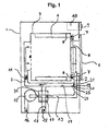
- the in Fig. 1 shown dryer 1 has a drum rotatable about a horizontal axis as a drying chamber 3, are mounted within which driver 4 for moving laundry during a drum rotation.
- Process air is conducted by means of a blower 12 via an electric heater 11, through a drum 3, in a process air duct 2.
- the process air channel 2 is supplied via a supply air duct 15 room air or sucked in by the blower 12.
- the moist, warm process air is split at a branch 19 into a circulating air flow in a recirculating air duct 14 and into an exhaust air flow in an exhaust air duct 13.
- the exhaust duct 13 is an air-to-air heat exchanger 23, in which the process air (here: exhaust air) cooled and is passed to the exhaust air outlet 16 after condensation of the moisture contained in it.
- a closure mechanism 20 comprising a first lint filter 21 and a flap 24.
- Lint filter 21 and flap 24 form an angle of 90 ° and are rotatable about a common axis of rotation 25.
- the dryer 1 In the dryer 1 is heated by the heater 11 from the rear air, ie from a door 5 opposite side of the drum 3, passed through the perforated bottom in the drum 3, comes there with the laundry to be dried in contact and flows through the filling of the Drum 3 to a second lint filter 6 within a closing the filling opening door 5. Subsequently, the process air flow in the door. 5 deflected downwards.
- the process air is essentially supplied in an exhaust duct 13 to the air-air heat exchanger 23, in which the warm, laden with moisture process air is cooled and then fed to an exhaust air outlet 16.
- the separated moisture is collected in a condensate pan 17, from where it can be removed, for example by pumping.
- room air supplied to the dryer 1 is used in the air-air heat exchanger 23 via the supply air duct 15.
- This supply air is heated by the warm, laden with moisture process air and then before entering the drying chamber 3 by means of the electric heater 11.
- a portion of the exiting from the drying chamber 3 warm, laden with moisture process air is diverted into a recirculating air duct 14 and fed through the electric heater 11 in turn into the drying chamber 3.
- the diverted process air from the recirculating air duct 14 and the supply air preheated in the air-air heat exchanger 23 are combined in front of the electric heater 11.
- the supply air flow can be regulated by an adjustable closure device 18 (for example, flaps 18).
- Fig. 3 shows an enlarged detail of a dryer 1, in which the closure device is shown in greater detail.
- a closure mechanism 20 comprising a first lint filter 21 having a first surface 22 and a second surface 23 and a flap 24.
- Lint filter 21 and flap 24 form an angle of 90 ° and are rotatable about a common axis of rotation 25.
- the lattice grate 21 separates the recirculating air channel 14 from the process air channel 2, so that process air coming from the drying chamber 3 can flow both through the lattice 21 through the recirculating air channel 14 and through the exhaust air channel 13.
Landscapes
- Engineering & Computer Science (AREA)
- Textile Engineering (AREA)
- Detail Structures Of Washing Machines And Dryers (AREA)
- Drying Of Solid Materials (AREA)
- Treatment Of Fiber Materials (AREA)
Claims (11)
- Séchoir (1) comprenant une chambre de séchage (3) pour des objets à sécher, un conduit d'arrivée d'air (15), un conduit d'air de processus (2), dans lequel se trouve un chauffage (11) pour le réchauffement de l'air de processus et l'air de processus réchauffé est guidé au moyen d'une soufflerie (12) sur les objets à sécher et peut être guidé par un conduit d'évacuation d'air (13) vers la sortie d'évacuation d'air (16), un conduit de circulation d'air (14) destiné au chauffage (11) déviant du conduit d'air de processus (2) entre la chambre de séchage (3) et la sortie d'évacuation d'air (16) sur une dérivation (19) et la partie restante du conduit d'air de processus (2) allant sous forme de conduit d'évacuation d'air (13) à la sortie d'évacuation d'air (16), caractérisé en ce qu'un mécanisme de fermeture (20) en deux parties, comprenant une grille à peluche (21) dotée d'une première surface (22) et d'une seconde surface (23) et un clapet (24), est disposé sur la dérivation (19), la grille à peluche (21) et le clapet (24) pouvant être tournés l'un par rapport à l'autre, de telle sorte que, lorsque le mécanisme de fermeture (20) est dans une première position, le clapet (24) sépare le conduit de circulation d'air (14) du conduit d'air de processus (2) et la grille à peluche (21) sépare le conduit d'évacuation d'air (13) du conduit d'air de processus (2), de sorte que l'air de processus arrivant de la chambre de séchage (3) continue de circuler exclusivement en traversant la grille à peluche (21) par le conduit d'évacuation d'air (13), et, lorsque le mécanisme de fermeture (20) est dans une seconde position, la grille à peluche (21) sépare le conduit de circulation d'air (14) du conduit d'air de processus (2), de sorte que de l'air de processus arrivant de la chambre de séchage (3) peut circuler aussi bien en traversant la grille à peluche (21) par le conduit de circulation d'air (14) que par le conduit d'évacuation d'air (13).
- Séchoir (1) selon la revendication 1, caractérisé en ce que le conduit de circulation d'air (14) se rejoint avant le chauffage (11) avec le conduit d'arrivée d'air (15).
- Séchoir (1) selon la revendication 1 ou 2, caractérisé en ce que la grille à peluche (21) et le clapet (24) peuvent être réglés en fonction l'un de l'autre ou indépendamment l'un de l'autre.
- Séchoir (1) selon la revendication 3, caractérisé en ce que la grille à peluche (21) et le clapet (24) forment un angle de 90°.
- Séchoir (1) selon la revendication 3 ou 4, caractérisé en ce que la grille à peluche (21) et le clapet (24) peuvent tourner autour d'un axe (25) commun.
- Séchoir (1) selon l'une des revendications précédentes, caractérisé en ce que la grille à peluche (21) comprend une partie de cadre disposée dans le dispositif de fermeture (20) et un filtre à peluche amovible.
- Séchoir (1) selon l'une des revendications précédentes, caractérisé en ce que le séchoir (1) comprend au moins un échangeur de chaleur (23 ; 19, 20).
- Séchoir (1) selon la revendication 7, caractérisé en ce qu'au moins l'un des échangeurs de chaleur (17 ; 19, 20) est un échangeur de chaleur air-air (23).
- Séchoir (1) selon l'une des revendications précédentes, caractérisé en ce qu'un premier dispositif de fermeture (26) contrôlable est disposé dans le conduit de circulation d'air (14).
- Séchoir (1) selon l'une des revendications précédentes, caractérisé en ce qu'un second dispositif de fermeture (18) contrôlable est disposé dans le conduit d'arrivée d'air (15).
- Procédé pour faire fonctionner un séchoir (1) comprenant une chambre de séchage (3) pour des objets à sécher, un conduit d'arrivée d'air (15), un conduit d'air de processus (2), dans lequel se trouve un chauffage (11) pour le réchauffement d'air de processus et l'air de processus réchauffé est guidé au moyen d'une soufflerie (12) sur les objets à sécher et peut être guidé par un conduit d'évacuation d'air (13) vers la sortie d'évacuation d'air (16), un conduit de circulation d'air (14) destiné au chauffage (11) déviant du conduit d'air de processus (2) entre la chambre de séchage (3) et la sortie d'évacuation d'air (16) sur une dérivation (19) et la partie restante du conduit d'air de processus (2) allant sous forme de conduit d'évacuation d'air (13) vers la sortie d'évacuation d'air (16), un mécanisme de fermeture (20) en deux parties, comprenant une grille à peluche (21) avec une première surface (22) et une seconde surface (23) et un clapet (24), étant disposé sur la dérivation (19), la grille à peluche (21) et le clapet (24) pouvant tourner l'un par rapport à l'autre, de telle sorte que, lorsque le mécanisme de fermeture (20) est dans une première position, le clapet (24) sépare le conduit de circulation d'air (14) du conduit d'air de processus (2) et la grille à peluche (21) sépare le conduit d'évacuation d'air (13) du conduit d'air de processus (2), de sorte que de l'air de processus arrivant de la chambre de séchage (3) continue de circuler uniquement en traversant la grille à peluche (21) par le conduit d'évacuation d'air (13), et, lorsque le mécanisme de fermeture (20) est dans une seconde position, la grille à peluche (21) sépare le conduit de circulation d'air (14) du conduit d'air de processus (2), de sorte que de l'air de processus arrivant de la chambre de séchage (3) peut circuler aussi bien en traversant la grille à peluche (21) par le conduit de circulation d'air (14) que par le conduit d'évacuation d'air (13), caractérisé en ce que le mécanisme de fermeture (20) est amené de la seconde position dans la première position, afin de débarrasser la grille à peluche (21) des peluches, par le fait que les peluches se trouvant sur la seconde surface (22) sont enlevées par l'air de processus entrant dans le conduit d'évacuation d'air (13).
Applications Claiming Priority (1)
| Application Number | Priority Date | Filing Date | Title |
|---|---|---|---|
| DE102008044284A DE102008044284A1 (de) | 2008-12-02 | 2008-12-02 | Trockner mit Umluftanteil sowie Verfahren zu seinem Betrieb |
Publications (3)
| Publication Number | Publication Date |
|---|---|
| EP2194183A2 EP2194183A2 (fr) | 2010-06-09 |
| EP2194183A3 EP2194183A3 (fr) | 2010-09-01 |
| EP2194183B1 true EP2194183B1 (fr) | 2012-01-18 |
Family
ID=42061044
Family Applications (1)
| Application Number | Title | Priority Date | Filing Date |
|---|---|---|---|
| EP09175927A Not-in-force EP2194183B1 (fr) | 2008-12-02 | 2009-11-13 | Séchoir doté d'une teneur en air ambiant et son procédé de fonctionnement |
Country Status (4)
| Country | Link |
|---|---|
| US (1) | US20100132217A1 (fr) |
| EP (1) | EP2194183B1 (fr) |
| AT (1) | ATE541983T1 (fr) |
| DE (1) | DE102008044284A1 (fr) |
Cited By (2)
| Publication number | Priority date | Publication date | Assignee | Title |
|---|---|---|---|---|
| US11186943B2 (en) | 2017-10-09 | 2021-11-30 | Whirlpool Corporation | Filter configured for being used in a machine for drying laundry and machine for drying laundry equipped with such a filter |
| EP4140385B1 (fr) * | 2020-05-28 | 2025-07-23 | Foshan Shunde Midea Washing Appliances Manufacturing Co., Ltd. | Appareil de nettoyage |
Families Citing this family (12)
| Publication number | Priority date | Publication date | Assignee | Title |
|---|---|---|---|---|
| DE102008044277A1 (de) * | 2008-12-02 | 2010-06-10 | BSH Bosch und Siemens Hausgeräte GmbH | Trockner mit einer Wärmepumpe und einer elektrischen Heizung sowie Verfahren zu seinem Betrieb |
| KR101704612B1 (ko) * | 2009-11-30 | 2017-02-08 | 삼성전자주식회사 | 식기세척기 및 그 제어방법 |
| CN102822410B (zh) * | 2010-08-09 | 2015-06-17 | Lg电子株式会社 | 干衣机 |
| US9695544B2 (en) * | 2012-04-02 | 2017-07-04 | Electrolux Home Products Corporation, N.V. | Dryer with air recirculation/heat exchange subassembly |
| CN103375386A (zh) * | 2012-04-26 | 2013-10-30 | 珠海格力电器股份有限公司 | 制冷压缩机及使用该制冷压缩机的空调器 |
| WO2013182403A1 (fr) * | 2012-06-05 | 2013-12-12 | Arcelik Anonim Sirketi | Sèche-linge ayant un condenseur refroidi à l'air |
| DE102012221914B4 (de) * | 2012-11-29 | 2021-09-16 | BSH Hausgeräte GmbH | Filteranordnung für eine Wäschebehandlungsmaschine |
| US9574298B2 (en) | 2013-06-07 | 2017-02-21 | Electrolux Appliances Aktiebolag | Laundry dryer with accessible recirculation air filter |
| CN105088713A (zh) * | 2014-04-17 | 2015-11-25 | 无锡小天鹅股份有限公司 | 洗干一体机 |
| US10138588B1 (en) * | 2016-06-07 | 2018-11-27 | Dock Foy, Jr. | Clothes dryer ventilation system |
| CN109944045B (zh) * | 2019-02-19 | 2022-06-17 | 青岛胶州海尔洗涤电器有限公司 | 一种干衣设备的排风结构及线屑清理方法 |
| JP2021156547A (ja) * | 2020-03-30 | 2021-10-07 | パナソニックIpマネジメント株式会社 | 換気装置 |
Family Cites Families (18)
| Publication number | Priority date | Publication date | Assignee | Title |
|---|---|---|---|---|
| US1427580A (en) * | 1922-02-14 | 1922-08-29 | Charles W Collins | Clothes-drying machine |
| US2818719A (en) * | 1952-05-19 | 1958-01-07 | Kermit R Cline | Combined washing and drying apparatus |
| US2712183A (en) * | 1952-11-15 | 1955-07-05 | John P Jorgenson | Clothes dryers |
| US3934545A (en) * | 1971-11-15 | 1976-01-27 | Alpha Sheet Metal Works, Inc. | Apparatus for enrobing discrete objects |
| US4268247A (en) * | 1979-05-24 | 1981-05-19 | Challenge-Cook Bros., Incorporated | Method for drying fabrics |
| DE3000865A1 (de) | 1980-01-11 | 1981-07-16 | Fichtel & Sachs Ag, 8720 Schweinfurt | Waeschetrockner mit waermerueckgewinnung |
| US4519145A (en) * | 1984-03-12 | 1985-05-28 | Magic Chef, Inc. | Electrostatic and moisture control system for automatic clothes dryers |
| DE3600058C2 (de) * | 1986-01-03 | 1995-09-07 | Gerhard Xander | Flusenfilter |
| DE8605014U1 (de) * | 1986-02-25 | 1986-04-24 | MTM Obermaier GmbH & Co KG, 6733 Haßloch | Vorrichtung zum selbsttätigen Reinigen eines Flusensiebes |
| DE4211011C2 (de) * | 1992-04-02 | 1996-08-22 | Bosch Siemens Hausgeraete | Haushalt-Wäschetrockner mit einem Prozeßluft-Kanal und einem Wärmetauscher |
| DE19952751B4 (de) * | 1999-11-02 | 2009-01-02 | BSH Bosch und Siemens Hausgeräte GmbH | Wäschetrockner mit einem selbstreinigenden Flusenfilter |
| DE10029428A1 (de) * | 2000-06-15 | 2002-01-03 | Bsh Bosch Siemens Hausgeraete | Luftführendes Haushaltsgerät mit waschbarem Filter |
| DE10135471A1 (de) * | 2001-07-20 | 2003-01-30 | Bsh Bosch Siemens Hausgeraete | Wäschetrockner mit herausnehmbarem Filter |
| DE10302864B4 (de) * | 2003-01-25 | 2010-08-05 | Electrolux Home Products Corporation N.V. | Wäschetrockner mit Umluftbetrieb und Verfahren zur Behandlung von Wäsche |
| JP2007319458A (ja) * | 2006-06-01 | 2007-12-13 | Matsushita Electric Ind Co Ltd | 洗濯乾燥機 |
| DE102006051505A1 (de) | 2006-10-31 | 2008-05-08 | BSH Bosch und Siemens Hausgeräte GmbH | Verfahren zum Betreiben eines Hausgeräts zur Pflege von Wäschestücken |
| DE102006061212B3 (de) * | 2006-12-22 | 2008-03-13 | BSH Bosch und Siemens Hausgeräte GmbH | Hausgerät und Verfahren zum Trocknen eines feuchten Gutes |
| DE102007011809A1 (de) | 2007-03-12 | 2008-09-18 | BSH Bosch und Siemens Hausgeräte GmbH | Trockner mit Wärmerückgewinnung sowie Verfahren zu seinem Betrieb |
-
2008
- 2008-12-02 DE DE102008044284A patent/DE102008044284A1/de not_active Withdrawn
-
2009
- 2009-11-13 EP EP09175927A patent/EP2194183B1/fr not_active Not-in-force
- 2009-11-13 AT AT09175927T patent/ATE541983T1/de active
- 2009-11-23 US US12/623,761 patent/US20100132217A1/en not_active Abandoned
Cited By (3)
| Publication number | Priority date | Publication date | Assignee | Title |
|---|---|---|---|---|
| US11186943B2 (en) | 2017-10-09 | 2021-11-30 | Whirlpool Corporation | Filter configured for being used in a machine for drying laundry and machine for drying laundry equipped with such a filter |
| US11761141B2 (en) | 2017-10-09 | 2023-09-19 | Whirlpool Corporation | Filter configured for being used in a machine for drying laundry and machine for drying laundry equipped with such a filter |
| EP4140385B1 (fr) * | 2020-05-28 | 2025-07-23 | Foshan Shunde Midea Washing Appliances Manufacturing Co., Ltd. | Appareil de nettoyage |
Also Published As
| Publication number | Publication date |
|---|---|
| EP2194183A3 (fr) | 2010-09-01 |
| EP2194183A2 (fr) | 2010-06-09 |
| DE102008044284A1 (de) | 2010-06-10 |
| US20100132217A1 (en) | 2010-06-03 |
| ATE541983T1 (de) | 2012-02-15 |
Similar Documents
| Publication | Publication Date | Title |
|---|---|---|
| EP2194183B1 (fr) | Séchoir doté d'une teneur en air ambiant et son procédé de fonctionnement | |
| EP2196577B1 (fr) | Séchoir doté d'une teneur en air ambiant et son procédé de fonctionnement | |
| DE102008033388B4 (de) | Trockner mit Wärmepumpenkreis | |
| EP2115208B1 (fr) | Sèche-linge à condensation équipé d'une pompe à chaleur et procédé pour faire fonctionner ce sèche-linge | |
| EP2199454B1 (fr) | Appareil ménager doté d'un canal d'aération ouvert | |
| EP2373840B1 (fr) | Séchoir par condensation avec carter | |
| DE102006061737B3 (de) | Kondensationstrockner mit einer Wärmepumpe sowie Verfahren zu seinem Betrieb | |
| DE102008014305A1 (de) | Ablufttrockner mit Umluftanteil sowie Verfahren zu seinem Betrieb | |
| EP2371258A2 (fr) | Lave-vaisselle doté d'une aération de seuil de porte | |
| EP2492389B1 (fr) | Sèche-linge doté d'un dispositif de filtre à peluches jetable | |
| EP2140061B1 (fr) | Sèche-linge à condensation et procédé permettant de faire fonctionner un sèche-linge à condensation | |
| DE102008020556A1 (de) | Ablufttrockner mit verminderter Kondensatbildung sowie Verfahren zu seinem Betrieb | |
| DE102007052839A1 (de) | Trockner mit Wärmepumpenkreis | |
| DE102008043920A1 (de) | Kondensationstrockner mit einer Wärmepumpe sowie Verfahren zu seinem Betrieb | |
| WO2013186114A1 (fr) | Sécheur à condensation équipé d'une pompe et procédé pour le faire fonctionner | |
| EP2160488B1 (fr) | Sécheur à condensation muni d'une pompe à chaleur, et procédé pour le faire fonctionner | |
| EP2194182A1 (fr) | Séchoir doté d'une pompe à chaleur et d'un chauffage électrique ainsi que son procédé de fonctionnement | |
| EP3026167B1 (fr) | Appareil de séchage du linge et procédé de fonctionnement d'un appareil de séchage du linge | |
| DE102009002482A1 (de) | Energieeffizienter Trockner und Verfahren zu seinem Betrieb | |
| EP0920830B1 (fr) | Procédé pour le séchage de la vaisselle dans un appareil électroménager | |
| DE102010029491A1 (de) | Baugruppe und Haushaltswäschetrockner mit dieser Baugruppe | |
| DE102007042969A1 (de) | Trockner mit Wärmerückgewinnung und Umluftanteil sowie Verfahren zu seinem Betrieb | |
| DE3148573A1 (de) | Waeschetrockner der trommelbauart | |
| EP1205592B1 (fr) | Armoire sèche-linge | |
| CH712920A2 (de) | Wäschetrockner. |
Legal Events
| Date | Code | Title | Description |
|---|---|---|---|
| PUAI | Public reference made under article 153(3) epc to a published international application that has entered the european phase |
Free format text: ORIGINAL CODE: 0009012 |
|
| AK | Designated contracting states |
Kind code of ref document: A2 Designated state(s): AT BE BG CH CY CZ DE DK EE ES FI FR GB GR HR HU IE IS IT LI LT LU LV MC MK MT NL NO PL PT RO SE SI SK SM TR |
|
| AX | Request for extension of the european patent |
Extension state: AL BA RS |
|
| PUAL | Search report despatched |
Free format text: ORIGINAL CODE: 0009013 |
|
| AK | Designated contracting states |
Kind code of ref document: A3 Designated state(s): AT BE BG CH CY CZ DE DK EE ES FI FR GB GR HR HU IE IS IT LI LT LU LV MC MK MT NL NO PL PT RO SE SI SK SM TR |
|
| AX | Request for extension of the european patent |
Extension state: AL BA RS |
|
| RIC1 | Information provided on ipc code assigned before grant |
Ipc: D06F 58/22 20060101ALI20100728BHEP Ipc: D06F 58/20 20060101ALI20100728BHEP Ipc: D06F 58/24 20060101AFI20100407BHEP |
|
| 17P | Request for examination filed |
Effective date: 20110301 |
|
| GRAP | Despatch of communication of intention to grant a patent |
Free format text: ORIGINAL CODE: EPIDOSNIGR1 |
|
| RIC1 | Information provided on ipc code assigned before grant |
Ipc: D06F 58/24 20060101AFI20110725BHEP Ipc: D06F 58/22 20060101ALI20110725BHEP Ipc: D06F 58/20 20060101ALI20110725BHEP |
|
| GRAS | Grant fee paid |
Free format text: ORIGINAL CODE: EPIDOSNIGR3 |
|
| GRAA | (expected) grant |
Free format text: ORIGINAL CODE: 0009210 |
|
| AK | Designated contracting states |
Kind code of ref document: B1 Designated state(s): AT BE BG CH CY CZ DE DK EE ES FI FR GB GR HR HU IE IS IT LI LT LU LV MC MK MT NL NO PL PT RO SE SI SK SM TR |
|
| REG | Reference to a national code |
Ref country code: GB Ref legal event code: FG4D Free format text: NOT ENGLISH |
|
| REG | Reference to a national code |
Ref country code: CH Ref legal event code: EP |
|
| REG | Reference to a national code |
Ref country code: AT Ref legal event code: REF Ref document number: 541983 Country of ref document: AT Kind code of ref document: T Effective date: 20120215 Ref country code: IE Ref legal event code: FG4D Free format text: LANGUAGE OF EP DOCUMENT: GERMAN |
|
| REG | Reference to a national code |
Ref country code: DE Ref legal event code: R096 Ref document number: 502009002476 Country of ref document: DE Effective date: 20120322 |
|
| REG | Reference to a national code |
Ref country code: NL Ref legal event code: VDEP Effective date: 20120118 |
|
| LTIE | Lt: invalidation of european patent or patent extension |
Effective date: 20120118 |
|
| PG25 | Lapsed in a contracting state [announced via postgrant information from national office to epo] |
Ref country code: HR Free format text: LAPSE BECAUSE OF FAILURE TO SUBMIT A TRANSLATION OF THE DESCRIPTION OR TO PAY THE FEE WITHIN THE PRESCRIBED TIME-LIMIT Effective date: 20120118 Ref country code: IS Free format text: LAPSE BECAUSE OF FAILURE TO SUBMIT A TRANSLATION OF THE DESCRIPTION OR TO PAY THE FEE WITHIN THE PRESCRIBED TIME-LIMIT Effective date: 20120518 Ref country code: NO Free format text: LAPSE BECAUSE OF FAILURE TO SUBMIT A TRANSLATION OF THE DESCRIPTION OR TO PAY THE FEE WITHIN THE PRESCRIBED TIME-LIMIT Effective date: 20120418 Ref country code: LT Free format text: LAPSE BECAUSE OF FAILURE TO SUBMIT A TRANSLATION OF THE DESCRIPTION OR TO PAY THE FEE WITHIN THE PRESCRIBED TIME-LIMIT Effective date: 20120118 Ref country code: NL Free format text: LAPSE BECAUSE OF FAILURE TO SUBMIT A TRANSLATION OF THE DESCRIPTION OR TO PAY THE FEE WITHIN THE PRESCRIBED TIME-LIMIT Effective date: 20120118 Ref country code: BG Free format text: LAPSE BECAUSE OF FAILURE TO SUBMIT A TRANSLATION OF THE DESCRIPTION OR TO PAY THE FEE WITHIN THE PRESCRIBED TIME-LIMIT Effective date: 20120418 |
|
| REG | Reference to a national code |
Ref country code: IE Ref legal event code: FD4D |
|
| PG25 | Lapsed in a contracting state [announced via postgrant information from national office to epo] |
Ref country code: PL Free format text: LAPSE BECAUSE OF FAILURE TO SUBMIT A TRANSLATION OF THE DESCRIPTION OR TO PAY THE FEE WITHIN THE PRESCRIBED TIME-LIMIT Effective date: 20120118 Ref country code: GR Free format text: LAPSE BECAUSE OF FAILURE TO SUBMIT A TRANSLATION OF THE DESCRIPTION OR TO PAY THE FEE WITHIN THE PRESCRIBED TIME-LIMIT Effective date: 20120419 Ref country code: PT Free format text: LAPSE BECAUSE OF FAILURE TO SUBMIT A TRANSLATION OF THE DESCRIPTION OR TO PAY THE FEE WITHIN THE PRESCRIBED TIME-LIMIT Effective date: 20120518 Ref country code: FI Free format text: LAPSE BECAUSE OF FAILURE TO SUBMIT A TRANSLATION OF THE DESCRIPTION OR TO PAY THE FEE WITHIN THE PRESCRIBED TIME-LIMIT Effective date: 20120118 Ref country code: LV Free format text: LAPSE BECAUSE OF FAILURE TO SUBMIT A TRANSLATION OF THE DESCRIPTION OR TO PAY THE FEE WITHIN THE PRESCRIBED TIME-LIMIT Effective date: 20120118 |
|
| PG25 | Lapsed in a contracting state [announced via postgrant information from national office to epo] |
Ref country code: CY Free format text: LAPSE BECAUSE OF FAILURE TO SUBMIT A TRANSLATION OF THE DESCRIPTION OR TO PAY THE FEE WITHIN THE PRESCRIBED TIME-LIMIT Effective date: 20120118 |
|
| PG25 | Lapsed in a contracting state [announced via postgrant information from national office to epo] |
Ref country code: EE Free format text: LAPSE BECAUSE OF FAILURE TO SUBMIT A TRANSLATION OF THE DESCRIPTION OR TO PAY THE FEE WITHIN THE PRESCRIBED TIME-LIMIT Effective date: 20120118 Ref country code: IE Free format text: LAPSE BECAUSE OF FAILURE TO SUBMIT A TRANSLATION OF THE DESCRIPTION OR TO PAY THE FEE WITHIN THE PRESCRIBED TIME-LIMIT Effective date: 20120118 Ref country code: CZ Free format text: LAPSE BECAUSE OF FAILURE TO SUBMIT A TRANSLATION OF THE DESCRIPTION OR TO PAY THE FEE WITHIN THE PRESCRIBED TIME-LIMIT Effective date: 20120118 Ref country code: DK Free format text: LAPSE BECAUSE OF FAILURE TO SUBMIT A TRANSLATION OF THE DESCRIPTION OR TO PAY THE FEE WITHIN THE PRESCRIBED TIME-LIMIT Effective date: 20120118 Ref country code: SE Free format text: LAPSE BECAUSE OF FAILURE TO SUBMIT A TRANSLATION OF THE DESCRIPTION OR TO PAY THE FEE WITHIN THE PRESCRIBED TIME-LIMIT Effective date: 20120118 Ref country code: SI Free format text: LAPSE BECAUSE OF FAILURE TO SUBMIT A TRANSLATION OF THE DESCRIPTION OR TO PAY THE FEE WITHIN THE PRESCRIBED TIME-LIMIT Effective date: 20120118 Ref country code: RO Free format text: LAPSE BECAUSE OF FAILURE TO SUBMIT A TRANSLATION OF THE DESCRIPTION OR TO PAY THE FEE WITHIN THE PRESCRIBED TIME-LIMIT Effective date: 20120118 |
|
| PLBE | No opposition filed within time limit |
Free format text: ORIGINAL CODE: 0009261 |
|
| STAA | Information on the status of an ep patent application or granted ep patent |
Free format text: STATUS: NO OPPOSITION FILED WITHIN TIME LIMIT |
|
| PG25 | Lapsed in a contracting state [announced via postgrant information from national office to epo] |
Ref country code: SK Free format text: LAPSE BECAUSE OF FAILURE TO SUBMIT A TRANSLATION OF THE DESCRIPTION OR TO PAY THE FEE WITHIN THE PRESCRIBED TIME-LIMIT Effective date: 20120118 |
|
| 26N | No opposition filed |
Effective date: 20121019 |
|
| REG | Reference to a national code |
Ref country code: DE Ref legal event code: R097 Ref document number: 502009002476 Country of ref document: DE Effective date: 20121019 |
|
| PG25 | Lapsed in a contracting state [announced via postgrant information from national office to epo] |
Ref country code: ES Free format text: LAPSE BECAUSE OF FAILURE TO SUBMIT A TRANSLATION OF THE DESCRIPTION OR TO PAY THE FEE WITHIN THE PRESCRIBED TIME-LIMIT Effective date: 20120429 |
|
| BERE | Be: lapsed |
Owner name: BSH BOSCH UND SIEMENS HAUSGERATE G.M.B.H. Effective date: 20121130 |
|
| PG25 | Lapsed in a contracting state [announced via postgrant information from national office to epo] |
Ref country code: BE Free format text: LAPSE BECAUSE OF NON-PAYMENT OF DUE FEES Effective date: 20121130 |
|
| PG25 | Lapsed in a contracting state [announced via postgrant information from national office to epo] |
Ref country code: MT Free format text: LAPSE BECAUSE OF FAILURE TO SUBMIT A TRANSLATION OF THE DESCRIPTION OR TO PAY THE FEE WITHIN THE PRESCRIBED TIME-LIMIT Effective date: 20120118 |
|
| PGFP | Annual fee paid to national office [announced via postgrant information from national office to epo] |
Ref country code: FR Payment date: 20131119 Year of fee payment: 5 |
|
| PGFP | Annual fee paid to national office [announced via postgrant information from national office to epo] |
Ref country code: IT Payment date: 20131126 Year of fee payment: 5 |
|
| PG25 | Lapsed in a contracting state [announced via postgrant information from national office to epo] |
Ref country code: TR Free format text: LAPSE BECAUSE OF FAILURE TO SUBMIT A TRANSLATION OF THE DESCRIPTION OR TO PAY THE FEE WITHIN THE PRESCRIBED TIME-LIMIT Effective date: 20120118 Ref country code: MC Free format text: LAPSE BECAUSE OF NON-PAYMENT OF DUE FEES Effective date: 20121130 |
|
| PG25 | Lapsed in a contracting state [announced via postgrant information from national office to epo] |
Ref country code: SM Free format text: LAPSE BECAUSE OF FAILURE TO SUBMIT A TRANSLATION OF THE DESCRIPTION OR TO PAY THE FEE WITHIN THE PRESCRIBED TIME-LIMIT Effective date: 20120118 Ref country code: LU Free format text: LAPSE BECAUSE OF NON-PAYMENT OF DUE FEES Effective date: 20121113 |
|
| REG | Reference to a national code |
Ref country code: CH Ref legal event code: PL |
|
| PG25 | Lapsed in a contracting state [announced via postgrant information from national office to epo] |
Ref country code: LI Free format text: LAPSE BECAUSE OF NON-PAYMENT OF DUE FEES Effective date: 20131130 Ref country code: HU Free format text: LAPSE BECAUSE OF FAILURE TO SUBMIT A TRANSLATION OF THE DESCRIPTION OR TO PAY THE FEE WITHIN THE PRESCRIBED TIME-LIMIT Effective date: 20091113 Ref country code: CH Free format text: LAPSE BECAUSE OF NON-PAYMENT OF DUE FEES Effective date: 20131130 |
|
| REG | Reference to a national code |
Ref country code: DE Ref legal event code: R081 Ref document number: 502009002476 Country of ref document: DE Owner name: BSH HAUSGERAETE GMBH, DE Free format text: FORMER OWNER: BSH BOSCH UND SIEMENS HAUSGERAETE GMBH, 81739 MUENCHEN, DE Effective date: 20150409 |
|
| PG25 | Lapsed in a contracting state [announced via postgrant information from national office to epo] |
Ref country code: MK Free format text: LAPSE BECAUSE OF FAILURE TO SUBMIT A TRANSLATION OF THE DESCRIPTION OR TO PAY THE FEE WITHIN THE PRESCRIBED TIME-LIMIT Effective date: 20120118 |
|
| REG | Reference to a national code |
Ref country code: FR Ref legal event code: ST Effective date: 20150731 |
|
| PG25 | Lapsed in a contracting state [announced via postgrant information from national office to epo] |
Ref country code: FR Free format text: LAPSE BECAUSE OF NON-PAYMENT OF DUE FEES Effective date: 20141201 |
|
| PG25 | Lapsed in a contracting state [announced via postgrant information from national office to epo] |
Ref country code: IT Free format text: LAPSE BECAUSE OF NON-PAYMENT OF DUE FEES Effective date: 20141113 |
|
| REG | Reference to a national code |
Ref country code: AT Ref legal event code: MM01 Ref document number: 541983 Country of ref document: AT Kind code of ref document: T Effective date: 20141113 |
|
| PG25 | Lapsed in a contracting state [announced via postgrant information from national office to epo] |
Ref country code: AT Free format text: LAPSE BECAUSE OF NON-PAYMENT OF DUE FEES Effective date: 20141113 |
|
| PGFP | Annual fee paid to national office [announced via postgrant information from national office to epo] |
Ref country code: DE Payment date: 20171130 Year of fee payment: 9 |
|
| PGFP | Annual fee paid to national office [announced via postgrant information from national office to epo] |
Ref country code: GB Payment date: 20171124 Year of fee payment: 9 |
|
| REG | Reference to a national code |
Ref country code: DE Ref legal event code: R119 Ref document number: 502009002476 Country of ref document: DE |
|
| GBPC | Gb: european patent ceased through non-payment of renewal fee |
Effective date: 20181113 |
|
| PG25 | Lapsed in a contracting state [announced via postgrant information from national office to epo] |
Ref country code: DE Free format text: LAPSE BECAUSE OF NON-PAYMENT OF DUE FEES Effective date: 20190601 |
|
| PG25 | Lapsed in a contracting state [announced via postgrant information from national office to epo] |
Ref country code: GB Free format text: LAPSE BECAUSE OF NON-PAYMENT OF DUE FEES Effective date: 20181113 |