EP2194202B1 - Procédé de fabrication d'un module spatial - Google Patents
Procédé de fabrication d'un module spatial Download PDFInfo
- Publication number
- EP2194202B1 EP2194202B1 EP20090177517 EP09177517A EP2194202B1 EP 2194202 B1 EP2194202 B1 EP 2194202B1 EP 20090177517 EP20090177517 EP 20090177517 EP 09177517 A EP09177517 A EP 09177517A EP 2194202 B1 EP2194202 B1 EP 2194202B1
- Authority
- EP
- European Patent Office
- Prior art keywords
- frame
- junction elements
- connecting beams
- beams
- frames
- Prior art date
- Legal status (The legal status is an assumption and is not a legal conclusion. Google has not performed a legal analysis and makes no representation as to the accuracy of the status listed.)
- Not-in-force
Links
Images




Classifications
-
- E—FIXED CONSTRUCTIONS
- E04—BUILDING
- E04B—GENERAL BUILDING CONSTRUCTIONS; WALLS, e.g. PARTITIONS; ROOFS; FLOORS; CEILINGS; INSULATION OR OTHER PROTECTION OF BUILDINGS
- E04B1/00—Constructions in general; Structures which are not restricted either to walls, e.g. partitions, or floors or ceilings or roofs
- E04B1/348—Structures composed of units comprising at least considerable parts of two sides of a room, e.g. box-like or cell-like units closed or in skeleton form
- E04B1/34815—Elements not integrated in a skeleton
- E04B1/34838—Elements not integrated in a skeleton the supporting structure consisting of wood
Definitions
- the invention relates to a method for producing a room module of a modular room system.
- the aim is to increase the degree of prefabrication of individual building components for the construction of buildings.
- the construction time required for the construction of a building can be significantly shortened.
- most of the construction costs can be reduced by increased automation of the production of prefabricated construction components.
- a high level of prefabrication is provided by modular room systems in which a building is composed of several container-type room modules.
- the room modules are known, which are prefabricated in timber frame construction and assembled on site at the construction site into a building.
- Different methods for producing room modules show DE 10348455 and DE 1946889 ,
- the present invention is based on the object to provide a method for producing a room module, with a building of prefabricated room modules of a modular room system can be easily assembled, the room modules are reusable and repeatedly assembled with other room modules of the modular room system can be.
- a room module is understood here and below to mean a module that can be combined with other room modules based on the same modular room system to form a building.
- a frame is understood here and below to be a polygonal, in particular square, frame, but the method according to the invention is just as suitable for triangular, pentagonal or polygonal frames.
- the first and second frames are disposed on opposite sides of the room module.
- a node element is understood to be one which is suitable for connecting at least two carriers to one another.
- the node element may be formed, for example, as a hollow body with contact surfaces for carriers and in particular have a plurality of openings for receiving threaded rods or screws for fastening a carrier to the node element. Some or all openings of such a node element may also be threaded.
- the node element may also be provided with fittings which cooperate with fittings on the end faces of the carrier to be connected and ensure a firm connection between node element and carrier.
- carrier is used uniformly for both, since the production method described below is fundamentally independent of whether the component designated by the carrier absorbs forces in the axial direction or transversely thereto.
- Stiffening in at least one further plane in the sense of claim 1 is understood here and below to mean stiffening in a plane which intersects the planes in which the first and the second frame lie.
- the at least one more level can in particular be such, in which are arranged between the frame connection carrier.
- the basic idea of the invention is to arrange the node elements of a plane of a spatial module with a gauge so exactly in space that they are also arranged to each other as that of a second spatial module whose nodes have been positioned with the same teaching to each other. This ensures that the nodes of two adjoining frames of adjacent room modules exactly over each other or abut each other, so that they can be easily and without further measures to compensate for manufacturing tolerances connected to each other, for example, screwed together, can be.
- the items of a room module z.
- As surface elements or rods, prefabricated with the lowest possible manufacturing tolerances and successively piece by piece connected to each other, without the position of the vertices of the room module is defined in advance. It is not possible even if the manufacturing tolerances for the individual carriers, the arrangement of the vertices of the room module exactly set because the tolerances allowed for components according to the standard ISO 1803, Part 3, from 2008 at 12 mm and more and any Add deviations from component to component.
- the corner points of the module space are at least plane-wise determined in advance by a teaching.
- dimensional accuracy of the prefabricated carriers is no longer important since the carriers can be shortened during fitting between the node elements or their length can be extended by the use of spacers, that their length corresponds exactly to the clear distance between two node elements to be connected.
- the corner points play a special role in the exact arrangement of the node elements, since the exact arrangement of the lengths of the side edges of the frame and the angle of the side edges are exactly defined to each other. Therefore, it is important to first set the corner points, and then adjust the length of the side beams between the corner points so that they can be fitted exactly between the node elements. For this purpose, it is preferable to first set the corner points on the teaching and only then insert the side support in between. But this is not absolutely necessary. If one or more side members are cut to size, they may be loosely connected to knot members and then placed on the jig together with the knot members before the length of the side members is adjusted to the clearance between the knots and then fixed to the knot members get connected.
- the frame is stiffened to maintain its shape. This can be done, for example, using struts inserted into the frame, which form a triangle, for example, together with parts of two adjacent, side-by-side side supports. Similarly, the frame can be stiffened over a one-sided or a two-sided planking. Another example of a stiffener is to insert pressure-resistant, insulated elements in the frame so that the clear space between the carriers is completely filled.
- node elements can be provided between the node elements at the corner points and accurately positioned over the same gauge or a teaching cooperating therewith.
- an exact positioning has the advantage that the node elements of adjacent room modules sit exactly on each other when the room modules are placed against each other or each other. In this case, the side beams are fitted between adjacent nodes.
- the length of a beam is adjusted as needed to the clear distance between two node elements to be connected. This can be done, for example, by fitting spacers into a gap remaining after the insertion of the carrier, or by cutting off an excess length. As spacers come for example cut to size wood elements into consideration, which in particular have the same cross section as the carrier. However, it is also possible to use one or more metal disks, plastic disks or the like of suitable thickness as spacers. The cutting off of an excess length is expediently carried out on a threaded end face of the carrier, in particular not on a provided with a threaded rod end face of the carrier.
- a preferred method of doing this is to fasten, align and adjust the connecting beams that are to connect the two frames to each other at the node elements of the first of the two frames so that the free end points of the beams are in the position required for the second frame.
- a further preferred example is to position the second frame with respect to the first frame by means of a jig, for example a gantry having defined support points for the first and second frames, and to insert connection girders between the opposing node elements of the first and second frames and in their length exactly at the clearance between the node elements, in particular in the manner described above by inserting one or more spacers or by cutting an excess length fit.
- a jig for example a gantry having defined support points for the first and second frames
- no complete container-like room module is attached to another, but it is a frame of the first room module used for the construction of the second room module.
- the second room module can be attached not only to the first or second frame of the first room module, but also to the frame of the first room module, which is formed by the corner points on one side of the room module and the intermediate side support and connecting beams.
- the second room module can be prefabricated in such a way that the third frame, the connection carrier connected thereto and a planking placed therebetween can be prefabricated as a room module open on one side, which then as a whole can only be prefabricated to an already existing one Room module must be attached and attached to it. Again, due to the dimensional accuracy of the second room module can be dispensed with a complex measurement and compensation technique.
- connection carriers to be fastened to the node elements can be components of prefabricated room module plates, in particular of prefabricated side walls.
- the node elements made of a very solid material, for example, a metal material, in particular steel or cast iron exist.
- the inventive method is particularly suitable for the production of wooden frame or wood stud constructions in which the carrier, in particular the side support and the connection carrier, but also any intermediate carrier, from a wood material, in particular wood or a wood composite material exist.
- a wood composite material is a wood-concrete composite material such as a composite material of wood and concrete or wood and resin or polymer concrete, for example, the brand Compono®, call, the concrete is then applied in particular on the upper side of the wearer a concrete layer.
- the carrying capacity of the carrier is significantly increased, so that longer spans are possible with the carrier.
- elements for connecting carriers in particular side or connecting beams, with the node elements are preferably threaded bolts or screws into consideration, which are dimensioned so that they can safely absorb the loads acting on them at the node elements.
- a threaded element accessible from the front side is additionally provided in the area of at least one end face of the carrier.
- the threaded element may for example be a composite anchor (in particular induo ® composite anchor of the Applicant) with a running in the longitudinal direction of the armature threaded bore which is inserted into a wooden rod forming the carrier at a distance from the end face of the wooden rod.
- exactly one end face of the carrier is provided with a threaded bolt prior to insertion between the node elements.
- the carrier when the carrier on one side with a protruding from the front side threaded bolt and on its other end face with an externally accessible, lying in the interior of the carrier thread for a threaded bolt or a screw is provided, the carrier can be particularly efficient between two nodes and attach to them.
- the carrier can be supported with its threaded bolt in the first node element, while on its other side a counter-mounted in the second node element threaded bolt is screwed into the thread. Finally, then only the threaded bolt of the carrier must be tightened by a nut in the first node element on this.
- the floor and ceiling structure is usually independent of the layout of a building created with a modular space system, it makes sense if the first and the second frame are each components of a floor or ceiling slab or a combination of floor and ceiling slab.
- At least one of the two frames is provided on at least one side, preferably on both sides, with a planking.
- a two-sided planking insulating material in particular a flameproof insulation, can be provided.
- the frame formed of side beams and connecting beams which can also be planked on one or both sides.
- At least two opposing side supports and / or connecting beams each have an outer side support member having a higher cross-section and an inner side support member having a lower cross section, which abut each other and are connected to each other, that the inner side support member on one side or on both sides opposite forms the outer side support member in height reset support or contact surface for an upper and / or lower or side planking.
- a concrete or reinforced concrete slab which is preferably flush with the upper edge of the outer beam, may also serve as the cladding.
- the frame construction together with the concrete or reinforced concrete cladding forms a floor and / or ceiling slab or a wall panel in Holzbetonverbundbauweise. With this type of solid construction is achieved over lightweight variants such as the timber frame construction, especially in terms of sound insulation and fire protection advantages.
- a concrete slab in the frame composite screws or the like may be provided which are anchored in the side beams and in the optionally provided intermediate carriers and protrude into the space provided for the concrete slab. Concrete is then poured into this room to produce the concrete slab.
- the shuttering required for this purpose can be defined for example by a pressure-resistant insulation, optionally provided intermediate carrier and the inner and outer side support members of the frame. In this way, in particular floor panels for the room module can be easily and effectively produced.
- solid panels preferably consisting of cross-laminated timber or board stacking elements, on or between the supports, so as to produce floor and / or ceiling elements or wall elements.
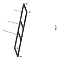
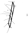
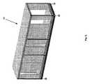
- FIGS. 1a to 1j schematically an example of a construction according to the invention of a room module is shown.
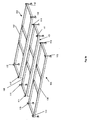
- a mobile steel frame 1 is used (s. FIG. 1a ).
- the rectangular steel frame 1 has two parallel to its short sides extending inner cross member 2, 3, which divide the rectangle of the steel frame 1 in the ratio of about 2: 1: 2.
- the position of the node elements within a room module and adjacent room modules to each other is clearly defined spatially.
- FIG. 1b It is shown how the node elements 4 to 7 on the vertices of the steel frame 1 and on the longitudinal sides of the steel frame between these node elements 4 to 7 further node elements 8 to 11 are placed.
- a planking 13 introduced between the node elements 4 to 11, which rest on the end faces of the steel frame 1 and the cross members 2, 3.
- Figure 1d Around the planking around then, as in Figure 1d can be seen, fitted between the respective adjacent node elements 4 and 5, 5 and 9, 9 and 10, 10 and 6, 6 and 7, 7 and 11, 11 and 8 and 8 and 4 side support 14 to 21 and with the node elements to firmly connected to a first frame.
- intermediate carrier 23, 24 are fitted and firmly connected with these.
- the node elements and the sides as well as subcarriers are flush with each other at their topsides. Not shown, but it is easy to imagine that any deviations of the carrier when fitting between the node elements are compensated by, for example, an excess length of the carrier is cut off or in the absence of sufficient length of the carrier spacers are inserted into the gap between a front side of the carrier and a node element ,
- connection carriers 33 to 40 the height of which is adapted to the height required for the room module, are set up and aligned on all node elements 4 to 11 (see FIG. FIG. 1h) .
- wall elements 42 are used as needed to spatially subdivide the room module (s. FIG. 1i ).
- the wall elements 42 which are firmly connected to the connecting beams 33 to 40, inter alia have the effect of stabilizing the connection carrier in position andconcentrsteifen the room module.
- the carriers side carrier, intermediate carrier, connecting carrier
- FIG. 1j Finally, it is to be seen how a second frame 43, which was composed just like the first frame (see FIG. FIGS. 1a to 1g ), finally placed on the connection carrier 33 to 40.
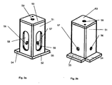
- a node element suitable for the vertices of the first and the second frame has a body of a square tube 51, on the underside of a base plate 52 and in the upper edge region of a lid 53 are welded.
- the base plate 52 is formed on two adjacent sides of the square tube 51 wider than the cross section of the square tube 51 and forms mutually offset by 90 ° support surfaces 54, 55 for carriers to be connected to the node element.
- through holes 56, 57 are respectively provided on the side of the square tube assigned to a support surface 54, 55.
- engagement openings 58, 59 to engage with tools in the square tube can, for example, to be able to screw a nut within the square tube on a guided through a through hole 56, 57 threaded bolt can.
- a central through-hole 59 for connecting a vertical connection carrier and in alignment therewith in the base plate 52 a further through-hole 61 is provided in the cover 53.
- the node element shown is intended for use in the corners of a first, lower frame of a room module, connected to the underside of a node element of another room module or directly a connection carrier of an adjacent room module can be attached.
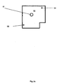
- connection points in the node elements for the corner points are the node elements for the vertices used for drilling the through holes in a doctrine, with which the positions of the through holes can be aligned exactly on the outer module in the edge module of the node element, as shown in Figure 2d by way of example.
- a node element which can be used as a connecting element between two side beams and an intermediate carrier, differs from that shown only in that the base plate has three mutually offset by 90 ° bearing surfaces for the horizontal carrier to be connected, and accordingly three through holes are provided in the square tube.
- a tool engagement opening is provided only in the side of the square tube to which no carrier is connected.
- threaded rods extending in the longitudinal direction may be embedded on the front side of the carrier.
- the threaded rods can be screwed, for example, into a composite anchors embedded in the carrier with a threaded bore running in the longitudinal direction or else glued into the carrier.
- the threaded rods are then inserted through the through holes of the node elements and fastened with nuts inserted in the node element.
- threads can be embedded in the end faces of the carrier. Then, the connection between the node element and the carrier takes place, for example, via a screw guided out of the interior of the node element through a through-hole and screwed into the thread of the carrier.
- a node element are attached to the fittings, which cooperate with suitable fittings on the end faces of the carrier.
- suitable fittings on the end faces of the carrier for example, connectors are considered, for example, under the name Sherpa by the company Vinzenz Harrer GmbH, Frohn meeting, Austria are offered.
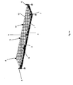
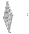
- FIGS. 3a to 3f an alternative inventive production method for a room module is shown.
- teachings 101 for making a floorboard or ceiling panel of a room module and teachings 102, 103 for making longitudinal side walls of the room module are shown.
- the length and width of the respective rectangular steel frames 106, 107, 108 of the gauges 101, 102, 103 substantially correspond respectively to the corresponding outer dimensions of the side of the space module (including floor and ceiling) for which a plate is to be formed on the gage.
- To the steel frame 106 - 108 are provided in particular at the corners possibilities for positioning and fastening of node elements (not shown).
- FIG. 3a The teachings 101-103 are shown with corner nodes 111, 112, 113.
- the corner nodes 111 for the bottom plate (or ceiling plate) stand with its base plate on the corners of the steel frame 106.
- the corner nodes 112, 113 are disposed on the steel frame 107, 108 for the production of wall elements of the room module, wherein the location of the corner nodes 112, 113 corresponds to the steel frame 112, 113 of the position of the corner nodes of the floor panel and the ceiling panel one side of the finished room module to the respective wall element.
- both the bottom plate 115 and the ceiling plate 116 of a room module to the reference to FIGS. 1a to 1g be prepared manner described.
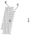
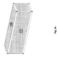
- connection carriers 117, 118 of a room module are produced in such a way that the connection carriers are fitted between the corner nodes on the end faces and screwed tightly thereto, the cut-off of an excess length of the connection carrier and / or the lengthening of the connection carrier being made by fitting spacers is to be understood on the connection carrier., So that the length of the connection carrier corresponds exactly to the clear distance between the two vertices,
- the gauges 102, 103 may be equipped with further node elements which, like the corner nodes, are horizontally arranged and whose position corresponds to the location of the nodes in a ceiling slab and a floor slab of a finished room module to which the wall elements to be manufactured are to be connected. In this case, then intermediate carrier between the node elements are fitted and bolted to the node elements.
- a wall element 117, 118 can then in principle be the same as it is for a floor or ceiling plate with respect to the Figures 1c to 1g is described.
- the side supports 15, 16, 17, 19, 20, 21 between the corner points of a floor or ceiling plate 115, 116 - preferably edge strips between the ends of the connection carrier and optionally the intermediate carrier fitted, which frame the space between the carriers .
- the wall elements 117, 118 are then placed with the lower end points of their connection and optionally intermediate carrier on the node elements of opposite sides of the bottom plate 115 and firmly screwed with these (s. 3d figure ).
- the ceiling plate is then mounted on the wall elements set up on the base plate, the node elements of the ceiling plate 116 being screwed to the upper end points of the connection carriers and, if appropriate, intermediate carriers ( FIG. 3e ).
- skins 119 are applied to the end faces of the room module as needed to close the room module.
- wall elements 117, 118 for the longitudinal walls of the room module and wall elements for the frontal walls of the room module can be prefabricated on appropriate gauges.
- the dimensions of the prefabricated wall elements 117, 118 as well as the ceiling and floor panels 115, 116 are so accurate that it can be made a space module of precisely defined size, the connection points formed by node elements are positioned so accurately that a plurality of room modules together to one Building can be connected without the need for special measures to compensate for manufacturing tolerances.
- At least one of the wall elements 117, 118 and the bottom plate 115 and / or the ceiling plate 116 stiffened by a partially or completely attached planking, alternatively or in addition thereto by solid insulation boards or other suitable means between the carriers, so that the room module is stabilized in all room dimensions.
- floor and ceiling panels openings for example, for doors, windows or staircases, can be embedded in the prefabrication.
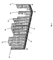
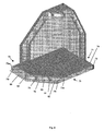
- the floor plate 71 which is of particular interest here, has a frame with node elements 72 and side supports 73, 74, 75 arranged at its corners.
- the side beams each consist of an inner side support member 73i, 75i and an outer side support member 73a, 75a which abut each other, wherein the outer side support members 73a, 75a have the same height as the node elements, while the inner side support members 73i, 75i have a lower height and with the outer side parts 73a, 75a only flush with the bottom side.
- composite anchors 76, 77 are inserted between the inner side support parts 73i, 75i and the outer side support parts 73a, 75a, which provide a threaded connection for connecting the support to the node element as so-called threaded or threaded push-through anchors on the front side of the support.
- Particularly suitable chemical anchors are so-called InDuo ® - composite anchor of the InDuo System Wood GmbH & Co. KG into consideration.
- a lower concrete plate 78 is bounded by the inner side support members 73i, 75i.
- a concrete plate 85 is also embedded in the space defined by the free inner side surfaces of the outer side support members 73a, 75a and the upper surfaces of the inner side support members 73i, 75i, the intermediate beams 79, 81 and the insulation panels 82, 83, 84.
- the concrete slabs 78, 85 are poured directly into the frame.
- the casing required for this purpose is formed on the upper side by the free inner side of the outer side support members 73a, 75a, and the upper sides of the inner side support members 73i, 75i, the intermediate beam 79, 81 and the insulating panels 82, 83, 84, the casing for the lower concrete slab 78 through the inner side of the inner side support members 73i, 75i and the lower surfaces of the intermediate beams 79, 81 and the Dämmplatte 82, 83, 84.
- the frame for casting the lower concrete slab 78 is rotated on its upper side. But it is also possible to use the floor on which the frame stands up as a shuttering for the casting of the lower concrete slab 78.
- wall elements can also be provided with a concrete slab.
- So-called wood concrete composite panels have the advantage that they have the advantages of a solid construction in terms of sound insulation and fire protection properties.
- As wood composite panels running wall elements are particularly preferably used for external wall elements of a building made with the modular room system.
Landscapes
- Engineering & Computer Science (AREA)
- Architecture (AREA)
- Physics & Mathematics (AREA)
- Electromagnetism (AREA)
- Civil Engineering (AREA)
- Structural Engineering (AREA)
- Joining Of Building Structures In Genera (AREA)
- Panels For Use In Building Construction (AREA)
- Automatic Assembly (AREA)
Claims (23)
- Procédé de fabrication d'un premier module d'espace d'un système d'espace modulaire, caractérisé par les étapes suivantes :a. détermination de points d'angle d'un premier châssis (1), en ce que des éléments nodaux (4-7) sont fixés dans la pièce avec un gabarit (1) ;b. mise en place de supports latéraux (14-21) entre les éléments nodaux (4-11) pour produire le premier châssis ;c. blindage du châssis produit ;d. production d'un deuxième châssis avec les étapes a. à c. ;e. montage du deuxième châssis dans une position définie par rapport au premier châssis, en liant les éléments nodaux correspondants des premier et deuxième châssis par des supports de liaison (33-40) ; etf. blindage du premier module d'espace produit avec les étapes a. à e. dans au moins un plan supplémentaire.
- Procédé selon la revendication 1, caractérisé en ce qu'à l'étape a., des éléments nodaux supplémentaires (8-11) sont fixés avec un gabarit entre les points d'angle.
- Procédé selon la revendication 1 ou 2, caractérisé en ce qu'à l'étape b., la longueur des supports latéraux (14-21) à placer entre les éléments nodaux (4-11) est adaptée précisément à l'écartement libre entre les éléments nodaux, soit en plaçant des entretoises soit en coupant une surlongueur.
- Procédé selon l'une des revendications 1 à 3, caractérisé en ce que l'étape e. comprend les étapes suivantes :e11. fixation de supports de liaison (33-40) sur les éléments nodaux (4-11) du premier châssis, avece12. alignement et adaptation des supports de liaison (33-40) de façon à ce que les points d'extrémité des supports de liaison (33-40) reposent dans le plan nécessaire au deuxième châssis ; ete13. fixation des éléments nodaux du deuxième châssis sur les points d'extrémité libres des supports (33-40).
- Procédé selon l'une des revendications 1 à 3, caractérisé en ce que l'étape e. comprend les étapes suivantes :e21. alignement du deuxième châssis par rapport au premier châssis à l'aide d'un gabarit ; ete22. mise en place des supports de liaison (33-40) entre les éléments nodaux se faisant face des premier et deuxième châssis.
- Procédé selon la revendication 5, caractérisé en ce qu'à l'étape e22., la longueur des supports de liaison (33-40) à mettre en place entre les éléments nodaux est adaptée précisément à l'écartement libre entre les éléments nodaux, soit en plaçant une ou plusieurs entretoise(s), soit en coupant une surlongueur.
- Procédé selon l'une des revendications 1 à 6, caractérisé en ce qu'au moins un deuxième module d'espace est produit avec les étapes suivantes :g. production d'un troisième châssis avec les étapes a. à c., sachant que les points d'angle du troisième châssis sont en corrélation avec des éléments nodaux du premier et/ou deuxième châssis du premier module d'espace ;h. montage du troisième châssis dans une position définie précisément par rapport aux éléments nodaux du premier et/ou deuxième châssis du premier module d'espace, avec liaison des éléments nodaux du premier et/ou deuxième châssis du premier module d'espace avec les éléments nodaux en corrélation avec ceux-ci du troisième châssis par des supports de liaison ; eti. blindage du deuxième module d'espace produit dans au moins un plan supplémentaire.
- Procédé selon la revendication 7, caractérisé en ce que l'étape h. comprend les étapes suivantes :h11. fixation de supports de liaison sur les éléments nodaux du troisième châssis, avech12. alignement et adaptation des supports de liaison de façon à ce que les points d'extrémité des supports de liaison reposent dans le plan nécessaire pour le raccordement au premier module d'espace ; eth13. fixation des éléments nodaux du premier module d'espace aux points d'extrémité libres des supports de liaison.
- Procédé selon la revendication 7, caractérisé en ce que l'étape h. comprend les étapes suivantes :h21. alignement du troisième châssis par rapport au châssis du premier module d'espace avec un gabarit ;eth22. mise en place des supports de liaison entre les éléments nodaux se faisant face du premier module d'espace et du troisième châssis.
- Procédé selon la revendication 4 ou l'une des revendications 7 à 9 dépendantes de cela ou selon la revendication 8, caractérisé en ce que les supports de liaison (33-40) à fixer aux éléments nodaux selon les étapes e11. à h11., sont des composantes de plaques de module d'espace préfabriquées, en particulier des parois latérales préfabriquées.
- Procédé selon l'une des revendications précédentes, caractérisé en ce que les éléments nodaux (4-11) sont en métal, en particulier en acier ou en fonte.
- Procédé selon l'une des revendications précédentes, caractérisé en ce qu'au moins un des supports latéraux (14-21) et/ou au moins un des supports de liaison (33-40) et/ou au moins un support intermédiaire (23, 24), en particulier tous les supports latéraux (14, 21) et/ou tous les supports de liaison (33-40) et/ou tous les supports intermédiaires (23, 24) sont en matériau de bois, en particulier en bois ou en matériau composite de bois.
- Procédé selon l'une des revendications précédentes, caractérisé en ce que les supports latéraux (14, 21) et les éléments nodaux (4-11) sont reliés entre eux via des boulons filetés respectivement des vis.
- Procédé selon la revendication 13, caractérisé en ce qu'au niveau d'au moins une face avant des supports latéraux (14-21) et/ou des supports de liaison (33-40), un élément de filetage accessible depuis la face avant est prévu.
- Procédé selon la revendication 13 ou 14, caractérisé en ce que précisément une face avant des supports latéraux (14-21) et/ou des supports de liaison (33-40) est dotée d'un boulon fileté avant la mise en place entre les éléments nodaux (4-11).
- Procédé selon la revendication 14 ou 15, caractérisé en ce que la coupe d'une surlongueur sur une face avant du support s'effectue dans la partie où le support est doté d'un filetage.
- Procédé selon l'une des revendications précédentes, caractérisé en ce que les châssis sont respectivement des composantes d'une dalle de sol (115) et/ou d'une dalle de plafond (116).
- Procédé selon la revendication 17, caractérisé en ce qu'au moins un support intermédiaire (23, 24) est disposé dans au moins un des châssis entre deux face opposées.
- Procédé selon l'une des revendications précédentes, caractérisé en ce qu'au moins un des deux châssis est doté d'un parement de cloison (13, 32) sur au moins une face, de préférence sur les deux faces.
- Procédé selon la revendication 19, caractérisé par du matériau isolant (28, 29, 30) dans l'espace libre entre un parement de cloison bilatéral (13, 32), en particulier une isolation résistant à la pression.
- Procédé selon la revendication 19 ou 20, caractérisé en ce qu'au moins deux supports latéraux opposés d'au moins un des châssis présentent respectivement une pièce porteuse latérale extérieure avec une section transversale plus haute et une pièce porteuse latérale intérieure avec une section transversale plus basse reposant dessus, de façon à ce que la pièce porteuse latérale intérieure forme un support pour un parement de cloison du châssis.
- Procédé selon la revendication 21, caractérisé par une plaque de béton (85) en tant que parement de cloison supérieur, qui se raccorde en affleurant avec le bord supérieur du support latéral extérieur.
- Procédé selon la revendication 22, caractérisé en ce que des vis composites dépassent des supports latéraux et de supports intermédiaires (79, 81) prévus le cas échéant, dans l'espace prévu pour la plaque de béton (85) qui est défini par une isolation (82, 83, 84) étanche à la pression, des supports intermédiaires (79, 81) prévus le cas échéant et les pièces porteuses latérales intérieure et extérieure (73i, 75i, 73a, 75a) du châssis, qui forment un coffrage, et en ce que du béton est coulé dans le coffrage pour produire la plaque de béton (85).
Applications Claiming Priority (1)
| Application Number | Priority Date | Filing Date | Title |
|---|---|---|---|
| DE102008060148 | 2008-12-03 |
Publications (3)
| Publication Number | Publication Date |
|---|---|
| EP2194202A2 EP2194202A2 (fr) | 2010-06-09 |
| EP2194202A3 EP2194202A3 (fr) | 2011-09-14 |
| EP2194202B1 true EP2194202B1 (fr) | 2013-01-02 |
Family
ID=41785705
Family Applications (1)
| Application Number | Title | Priority Date | Filing Date |
|---|---|---|---|
| EP20090177517 Not-in-force EP2194202B1 (fr) | 2008-12-03 | 2009-11-30 | Procédé de fabrication d'un module spatial |
Country Status (1)
| Country | Link |
|---|---|
| EP (1) | EP2194202B1 (fr) |
Cited By (1)
| Publication number | Priority date | Publication date | Assignee | Title |
|---|---|---|---|---|
| EP4610446A1 (fr) * | 2024-02-29 | 2025-09-03 | Domingos Da Silva Teixeira, S.A. | Dispositif de déplacement et de mise à niveau d'un module de pièce préfabriquée et procédé d'installation correspondant |
Families Citing this family (5)
| Publication number | Priority date | Publication date | Assignee | Title |
|---|---|---|---|---|
| RU2012153211A (ru) * | 2012-12-07 | 2014-06-20 | Александр Николаевич Емельянов | Клееная балка, анкер для крепления в клееную балку, узловое соединение клееных балок |
| DE202015101507U1 (de) | 2015-03-25 | 2015-06-19 | Alexander Emelianov | Brettschichtträger , Brettschichtträgerverankerung, Brettschitträgerknottverbindung |
| CN114182864B (zh) * | 2022-01-11 | 2025-12-19 | 中国铁建重工集团股份有限公司 | 一种承压房能内部安装的房底 |
| CN115807482B (zh) * | 2022-11-21 | 2025-09-05 | 中建集成科技有限公司 | 一种大空间大跨度可拓展箱式集成房屋及其施工方法 |
| EP4528043A1 (fr) * | 2023-09-20 | 2025-03-26 | Hitachi Energy Ltd | Ossature de plancher pour un bâtiment et bâtiment |
Family Cites Families (2)
| Publication number | Priority date | Publication date | Assignee | Title |
|---|---|---|---|---|
| DE1946889A1 (de) * | 1968-09-16 | 1970-05-06 | Stirling Homex Corp | Montageband zum Herstellen von Wohneinheiten und Verfahren zum Herstellen dieser Wohneinheiten |
| DE10348455B4 (de) * | 2003-10-14 | 2005-11-03 | Wolfgang Preschan | Vorrichtung in Form eines Bauwerks sowie Verfahren zum Errichten eines solchen Bauwerks |
-
2009
- 2009-11-30 EP EP20090177517 patent/EP2194202B1/fr not_active Not-in-force
Cited By (1)
| Publication number | Priority date | Publication date | Assignee | Title |
|---|---|---|---|---|
| EP4610446A1 (fr) * | 2024-02-29 | 2025-09-03 | Domingos Da Silva Teixeira, S.A. | Dispositif de déplacement et de mise à niveau d'un module de pièce préfabriquée et procédé d'installation correspondant |
Also Published As
| Publication number | Publication date |
|---|---|
| EP2194202A2 (fr) | 2010-06-09 |
| EP2194202A3 (fr) | 2011-09-14 |
Similar Documents
| Publication | Publication Date | Title |
|---|---|---|
| DE3880900T2 (de) | Bauelement mit vorgefertigten Wänden. | |
| AT509682B1 (de) | Verbindungselement für fertigteilelemente | |
| DE3303190C2 (de) | Bausatz zur Erstellung mobiler Bauten, insbesondere für Messe- und Ausstellungsbauten | |
| CH672519A5 (fr) | ||
| EP2194202A2 (fr) | Procédé de fabrication d'un module spatial | |
| DE69019979T2 (de) | Verfahren zur errichtung von gebäuden und bausatz zur ausführung des verfahrens. | |
| EP0385923B1 (fr) | Elément de construction pour la construction de bâtiments, parties de bâtiments ou similaire | |
| DE2049552A1 (de) | Vorfabriziertes Gebäude | |
| DE69903131T2 (de) | Modulares bauelement | |
| EP1931832A2 (fr) | Poteau mixte destine a des raccords a goussets de batiments et structure de batiment | |
| EP0843053A1 (fr) | Accouplement par friction entre poteaux et poutres ou entre poutres | |
| EP1840288A2 (fr) | Agencement destiné au stockage d'objets à l'aide d'éléments de construction dans un mur constitué d'éléments préfabriqués et son procédé de fixation | |
| DE8901471U1 (de) | Verbindungsstütze zur Erstellung von Container-Gehäusen bzw. Fertigbauraumkörpern | |
| AT405067B (de) | Anordnung zur verbindung von balken in einem gebäude und verfahren zur herstellung eines gebäude-skeletts unter verwendung von miteinander verbundenen balken | |
| DE2836863A1 (de) | Tragstruktur mit vorgefertigten vertikalen und horizontalen elementen, die pfeiler bzw. deckenplatten bilden | |
| DE3214502C2 (fr) | ||
| DE9409626U1 (de) | Balkonkonstruktion | |
| DE4100796C2 (de) | Leichtbauelement | |
| WO2004065708A1 (fr) | Noeud d'assemblage pour constructions en treillis tridimensionnel | |
| DE69001688T2 (de) | Verfahren zur befestigung von horizontalen balken an stahlsaeulen eines gebaeudes und ein nach diesem verfahren errichtetes gebaeude. | |
| EP1063361A2 (fr) | Gabarit de montage et procédé de montage d'un élément préfabriqué sur une partie de bâtiment | |
| AT528235B1 (de) | Bausatz für einen Brüstungsaufbau an einem Gebäude | |
| DE2548298C2 (de) | Verfahren und Hohlraumverschalungswand zum Bauen einer Hohlmauer | |
| DE202005006228U1 (de) | Dachkonstruktion für Gebäude, insbesondere für Industriegebäude mit großen Spannweiten | |
| DE2750931C2 (fr) |
Legal Events
| Date | Code | Title | Description |
|---|---|---|---|
| PUAI | Public reference made under article 153(3) epc to a published international application that has entered the european phase |
Free format text: ORIGINAL CODE: 0009012 |
|
| AK | Designated contracting states |
Kind code of ref document: A2 Designated state(s): AT BE BG CH CY CZ DE DK EE ES FI FR GB GR HR HU IE IS IT LI LT LU LV MC MK MT NL NO PL PT RO SE SI SK SM TR |
|
| AX | Request for extension of the european patent |
Extension state: AL BA RS |
|
| PUAL | Search report despatched |
Free format text: ORIGINAL CODE: 0009013 |
|
| AK | Designated contracting states |
Kind code of ref document: A3 Designated state(s): AT BE BG CH CY CZ DE DK EE ES FI FR GB GR HR HU IE IS IT LI LT LU LV MC MK MT NL NO PL PT RO SE SI SK SM TR |
|
| AX | Request for extension of the european patent |
Extension state: AL BA RS |
|
| RIC1 | Information provided on ipc code assigned before grant |
Ipc: E04B 1/348 20060101AFI20110810BHEP |
|
| 17P | Request for examination filed |
Effective date: 20120229 |
|
| GRAP | Despatch of communication of intention to grant a patent |
Free format text: ORIGINAL CODE: EPIDOSNIGR1 |
|
| GRAS | Grant fee paid |
Free format text: ORIGINAL CODE: EPIDOSNIGR3 |
|
| GRAP | Despatch of communication of intention to grant a patent |
Free format text: ORIGINAL CODE: EPIDOSNIGR1 |
|
| GRAA | (expected) grant |
Free format text: ORIGINAL CODE: 0009210 |
|
| AK | Designated contracting states |
Kind code of ref document: B1 Designated state(s): AT BE BG CH CY CZ DE DK EE ES FI FR GB GR HR HU IE IS IT LI LT LU LV MC MK MT NL NO PL PT RO SE SI SK SM TR |
|
| REG | Reference to a national code |
Ref country code: GB Ref legal event code: FG4D Free format text: NOT ENGLISH |
|
| REG | Reference to a national code |
Ref country code: AT Ref legal event code: REF Ref document number: 591720 Country of ref document: AT Kind code of ref document: T Effective date: 20130115 Ref country code: CH Ref legal event code: EP |
|
| REG | Reference to a national code |
Ref country code: IE Ref legal event code: FG4D Free format text: LANGUAGE OF EP DOCUMENT: GERMAN |
|
| REG | Reference to a national code |
Ref country code: DE Ref legal event code: R096 Ref document number: 502009005870 Country of ref document: DE Effective date: 20130307 |
|
| REG | Reference to a national code |
Ref country code: NL Ref legal event code: VDEP Effective date: 20130102 |
|
| PG25 | Lapsed in a contracting state [announced via postgrant information from national office to epo] |
Ref country code: SI Free format text: LAPSE BECAUSE OF FAILURE TO SUBMIT A TRANSLATION OF THE DESCRIPTION OR TO PAY THE FEE WITHIN THE PRESCRIBED TIME-LIMIT Effective date: 20130102 |
|
| REG | Reference to a national code |
Ref country code: LT Ref legal event code: MG4D |
|
| PG25 | Lapsed in a contracting state [announced via postgrant information from national office to epo] |
Ref country code: IS Free format text: LAPSE BECAUSE OF FAILURE TO SUBMIT A TRANSLATION OF THE DESCRIPTION OR TO PAY THE FEE WITHIN THE PRESCRIBED TIME-LIMIT Effective date: 20130502 Ref country code: NO Free format text: LAPSE BECAUSE OF FAILURE TO SUBMIT A TRANSLATION OF THE DESCRIPTION OR TO PAY THE FEE WITHIN THE PRESCRIBED TIME-LIMIT Effective date: 20130402 Ref country code: CZ Free format text: LAPSE BECAUSE OF FAILURE TO SUBMIT A TRANSLATION OF THE DESCRIPTION OR TO PAY THE FEE WITHIN THE PRESCRIBED TIME-LIMIT Effective date: 20130102 Ref country code: BG Free format text: LAPSE BECAUSE OF FAILURE TO SUBMIT A TRANSLATION OF THE DESCRIPTION OR TO PAY THE FEE WITHIN THE PRESCRIBED TIME-LIMIT Effective date: 20130402 Ref country code: LT Free format text: LAPSE BECAUSE OF FAILURE TO SUBMIT A TRANSLATION OF THE DESCRIPTION OR TO PAY THE FEE WITHIN THE PRESCRIBED TIME-LIMIT Effective date: 20130102 Ref country code: SE Free format text: LAPSE BECAUSE OF FAILURE TO SUBMIT A TRANSLATION OF THE DESCRIPTION OR TO PAY THE FEE WITHIN THE PRESCRIBED TIME-LIMIT Effective date: 20130102 Ref country code: ES Free format text: LAPSE BECAUSE OF FAILURE TO SUBMIT A TRANSLATION OF THE DESCRIPTION OR TO PAY THE FEE WITHIN THE PRESCRIBED TIME-LIMIT Effective date: 20130413 |
|
| PG25 | Lapsed in a contracting state [announced via postgrant information from national office to epo] |
Ref country code: FI Free format text: LAPSE BECAUSE OF FAILURE TO SUBMIT A TRANSLATION OF THE DESCRIPTION OR TO PAY THE FEE WITHIN THE PRESCRIBED TIME-LIMIT Effective date: 20130102 Ref country code: NL Free format text: LAPSE BECAUSE OF FAILURE TO SUBMIT A TRANSLATION OF THE DESCRIPTION OR TO PAY THE FEE WITHIN THE PRESCRIBED TIME-LIMIT Effective date: 20130102 Ref country code: GR Free format text: LAPSE BECAUSE OF FAILURE TO SUBMIT A TRANSLATION OF THE DESCRIPTION OR TO PAY THE FEE WITHIN THE PRESCRIBED TIME-LIMIT Effective date: 20130403 Ref country code: PT Free format text: LAPSE BECAUSE OF FAILURE TO SUBMIT A TRANSLATION OF THE DESCRIPTION OR TO PAY THE FEE WITHIN THE PRESCRIBED TIME-LIMIT Effective date: 20130502 Ref country code: LV Free format text: LAPSE BECAUSE OF FAILURE TO SUBMIT A TRANSLATION OF THE DESCRIPTION OR TO PAY THE FEE WITHIN THE PRESCRIBED TIME-LIMIT Effective date: 20130102 Ref country code: PL Free format text: LAPSE BECAUSE OF FAILURE TO SUBMIT A TRANSLATION OF THE DESCRIPTION OR TO PAY THE FEE WITHIN THE PRESCRIBED TIME-LIMIT Effective date: 20130102 |
|
| PG25 | Lapsed in a contracting state [announced via postgrant information from national office to epo] |
Ref country code: HR Free format text: LAPSE BECAUSE OF FAILURE TO SUBMIT A TRANSLATION OF THE DESCRIPTION OR TO PAY THE FEE WITHIN THE PRESCRIBED TIME-LIMIT Effective date: 20130102 |
|
| PG25 | Lapsed in a contracting state [announced via postgrant information from national office to epo] |
Ref country code: RO Free format text: LAPSE BECAUSE OF FAILURE TO SUBMIT A TRANSLATION OF THE DESCRIPTION OR TO PAY THE FEE WITHIN THE PRESCRIBED TIME-LIMIT Effective date: 20130102 Ref country code: EE Free format text: LAPSE BECAUSE OF FAILURE TO SUBMIT A TRANSLATION OF THE DESCRIPTION OR TO PAY THE FEE WITHIN THE PRESCRIBED TIME-LIMIT Effective date: 20130102 Ref country code: DK Free format text: LAPSE BECAUSE OF FAILURE TO SUBMIT A TRANSLATION OF THE DESCRIPTION OR TO PAY THE FEE WITHIN THE PRESCRIBED TIME-LIMIT Effective date: 20130102 Ref country code: SK Free format text: LAPSE BECAUSE OF FAILURE TO SUBMIT A TRANSLATION OF THE DESCRIPTION OR TO PAY THE FEE WITHIN THE PRESCRIBED TIME-LIMIT Effective date: 20130102 |
|
| PLBE | No opposition filed within time limit |
Free format text: ORIGINAL CODE: 0009261 |
|
| STAA | Information on the status of an ep patent application or granted ep patent |
Free format text: STATUS: NO OPPOSITION FILED WITHIN TIME LIMIT |
|
| PG25 | Lapsed in a contracting state [announced via postgrant information from national office to epo] |
Ref country code: CY Free format text: LAPSE BECAUSE OF FAILURE TO SUBMIT A TRANSLATION OF THE DESCRIPTION OR TO PAY THE FEE WITHIN THE PRESCRIBED TIME-LIMIT Effective date: 20130102 |
|
| 26N | No opposition filed |
Effective date: 20131003 |
|
| PG25 | Lapsed in a contracting state [announced via postgrant information from national office to epo] |
Ref country code: IT Free format text: LAPSE BECAUSE OF FAILURE TO SUBMIT A TRANSLATION OF THE DESCRIPTION OR TO PAY THE FEE WITHIN THE PRESCRIBED TIME-LIMIT Effective date: 20130102 |
|
| REG | Reference to a national code |
Ref country code: DE Ref legal event code: R097 Ref document number: 502009005870 Country of ref document: DE Effective date: 20131003 |
|
| PGFP | Annual fee paid to national office [announced via postgrant information from national office to epo] |
Ref country code: GB Payment date: 20131125 Year of fee payment: 5 |
|
| BERE | Be: lapsed |
Owner name: INDUO G.- ZUR VERWERTUNG VON SCHUTZRECHTEN MBH & Effective date: 20131130 |
|
| REG | Reference to a national code |
Ref country code: CH Ref legal event code: PL |
|
| PG25 | Lapsed in a contracting state [announced via postgrant information from national office to epo] |
Ref country code: MC Free format text: LAPSE BECAUSE OF FAILURE TO SUBMIT A TRANSLATION OF THE DESCRIPTION OR TO PAY THE FEE WITHIN THE PRESCRIBED TIME-LIMIT Effective date: 20130102 Ref country code: CH Free format text: LAPSE BECAUSE OF NON-PAYMENT OF DUE FEES Effective date: 20131130 Ref country code: LI Free format text: LAPSE BECAUSE OF NON-PAYMENT OF DUE FEES Effective date: 20131130 |
|
| REG | Reference to a national code |
Ref country code: FR Ref legal event code: ST Effective date: 20140731 |
|
| REG | Reference to a national code |
Ref country code: IE Ref legal event code: MM4A |
|
| PG25 | Lapsed in a contracting state [announced via postgrant information from national office to epo] |
Ref country code: BE Free format text: LAPSE BECAUSE OF NON-PAYMENT OF DUE FEES Effective date: 20131130 |
|
| PG25 | Lapsed in a contracting state [announced via postgrant information from national office to epo] |
Ref country code: IE Free format text: LAPSE BECAUSE OF NON-PAYMENT OF DUE FEES Effective date: 20131130 |
|
| PG25 | Lapsed in a contracting state [announced via postgrant information from national office to epo] |
Ref country code: FR Free format text: LAPSE BECAUSE OF NON-PAYMENT OF DUE FEES Effective date: 20131202 |
|
| PG25 | Lapsed in a contracting state [announced via postgrant information from national office to epo] |
Ref country code: SM Free format text: LAPSE BECAUSE OF FAILURE TO SUBMIT A TRANSLATION OF THE DESCRIPTION OR TO PAY THE FEE WITHIN THE PRESCRIBED TIME-LIMIT Effective date: 20130102 |
|
| PG25 | Lapsed in a contracting state [announced via postgrant information from national office to epo] |
Ref country code: TR Free format text: LAPSE BECAUSE OF FAILURE TO SUBMIT A TRANSLATION OF THE DESCRIPTION OR TO PAY THE FEE WITHIN THE PRESCRIBED TIME-LIMIT Effective date: 20130102 |
|
| GBPC | Gb: european patent ceased through non-payment of renewal fee |
Effective date: 20141130 |
|
| PG25 | Lapsed in a contracting state [announced via postgrant information from national office to epo] |
Ref country code: LU Free format text: LAPSE BECAUSE OF NON-PAYMENT OF DUE FEES Effective date: 20131130 Ref country code: HU Free format text: LAPSE BECAUSE OF FAILURE TO SUBMIT A TRANSLATION OF THE DESCRIPTION OR TO PAY THE FEE WITHIN THE PRESCRIBED TIME-LIMIT; INVALID AB INITIO Effective date: 20091130 Ref country code: MK Free format text: LAPSE BECAUSE OF FAILURE TO SUBMIT A TRANSLATION OF THE DESCRIPTION OR TO PAY THE FEE WITHIN THE PRESCRIBED TIME-LIMIT Effective date: 20130102 |
|
| PG25 | Lapsed in a contracting state [announced via postgrant information from national office to epo] |
Ref country code: MT Free format text: LAPSE BECAUSE OF FAILURE TO SUBMIT A TRANSLATION OF THE DESCRIPTION OR TO PAY THE FEE WITHIN THE PRESCRIBED TIME-LIMIT Effective date: 20130102 |
|
| PG25 | Lapsed in a contracting state [announced via postgrant information from national office to epo] |
Ref country code: GB Free format text: LAPSE BECAUSE OF NON-PAYMENT OF DUE FEES Effective date: 20141130 |
|
| REG | Reference to a national code |
Ref country code: AT Ref legal event code: MM01 Ref document number: 591720 Country of ref document: AT Kind code of ref document: T Effective date: 20141130 |
|
| PG25 | Lapsed in a contracting state [announced via postgrant information from national office to epo] |
Ref country code: AT Free format text: LAPSE BECAUSE OF NON-PAYMENT OF DUE FEES Effective date: 20141130 |
|
| PGFP | Annual fee paid to national office [announced via postgrant information from national office to epo] |
Ref country code: DE Payment date: 20220125 Year of fee payment: 13 |
|
| REG | Reference to a national code |
Ref country code: DE Ref legal event code: R119 Ref document number: 502009005870 Country of ref document: DE |
|
| PG25 | Lapsed in a contracting state [announced via postgrant information from national office to epo] |
Ref country code: DE Free format text: LAPSE BECAUSE OF NON-PAYMENT OF DUE FEES Effective date: 20230601 |