EP2194231A1 - Diffuseur annulaire pour une turbomachine axiale - Google Patents
Diffuseur annulaire pour une turbomachine axiale Download PDFInfo
- Publication number
- EP2194231A1 EP2194231A1 EP08021216A EP08021216A EP2194231A1 EP 2194231 A1 EP2194231 A1 EP 2194231A1 EP 08021216 A EP08021216 A EP 08021216A EP 08021216 A EP08021216 A EP 08021216A EP 2194231 A1 EP2194231 A1 EP 2194231A1
- Authority
- EP
- European Patent Office
- Prior art keywords
- wall
- diffuser
- wall surface
- ring diffuser
- axial
- Prior art date
- Legal status (The legal status is an assumption and is not a legal conclusion. Google has not performed a legal analysis and makes no representation as to the accuracy of the status listed.)
- Withdrawn
Links
Images


Classifications
-
- F—MECHANICAL ENGINEERING; LIGHTING; HEATING; WEAPONS; BLASTING
- F01—MACHINES OR ENGINES IN GENERAL; ENGINE PLANTS IN GENERAL; STEAM ENGINES
- F01D—NON-POSITIVE DISPLACEMENT MACHINES OR ENGINES, e.g. STEAM TURBINES
- F01D5/00—Blades; Blade-carrying members; Heating, heat-insulating, cooling or antivibration means on the blades or the members
- F01D5/12—Blades
- F01D5/14—Form or construction
- F01D5/141—Shape, i.e. outer, aerodynamic form
- F01D5/142—Shape, i.e. outer, aerodynamic form of the blades of successive rotor or stator blade-rows
- F01D5/143—Contour of the outer or inner working fluid flow path wall, i.e. shroud or hub contour
-
- F—MECHANICAL ENGINEERING; LIGHTING; HEATING; WEAPONS; BLASTING
- F01—MACHINES OR ENGINES IN GENERAL; ENGINE PLANTS IN GENERAL; STEAM ENGINES
- F01D—NON-POSITIVE DISPLACEMENT MACHINES OR ENGINES, e.g. STEAM TURBINES
- F01D5/00—Blades; Blade-carrying members; Heating, heat-insulating, cooling or antivibration means on the blades or the members
- F01D5/12—Blades
- F01D5/14—Form or construction
- F01D5/141—Shape, i.e. outer, aerodynamic form
- F01D5/145—Means for influencing boundary layers or secondary circulations
-
- F—MECHANICAL ENGINEERING; LIGHTING; HEATING; WEAPONS; BLASTING
- F05—INDEXING SCHEMES RELATING TO ENGINES OR PUMPS IN VARIOUS SUBCLASSES OF CLASSES F01-F04
- F05D—INDEXING SCHEME FOR ASPECTS RELATING TO NON-POSITIVE-DISPLACEMENT MACHINES OR ENGINES, GAS-TURBINES OR JET-PROPULSION PLANTS
- F05D2250/00—Geometry
- F05D2250/10—Two-dimensional
- F05D2250/18—Two-dimensional patterned
- F05D2250/184—Two-dimensional patterned sinusoidal
-
- Y—GENERAL TAGGING OF NEW TECHNOLOGICAL DEVELOPMENTS; GENERAL TAGGING OF CROSS-SECTIONAL TECHNOLOGIES SPANNING OVER SEVERAL SECTIONS OF THE IPC; TECHNICAL SUBJECTS COVERED BY FORMER USPC CROSS-REFERENCE ART COLLECTIONS [XRACs] AND DIGESTS
- Y02—TECHNOLOGIES OR APPLICATIONS FOR MITIGATION OR ADAPTATION AGAINST CLIMATE CHANGE
- Y02T—CLIMATE CHANGE MITIGATION TECHNOLOGIES RELATED TO TRANSPORTATION
- Y02T50/00—Aeronautics or air transport
- Y02T50/60—Efficient propulsion technologies, e.g. for aircraft
Definitions
- the invention relates to a ring diffuser for an axial turbomachine having a circular outer wall and a circular inner wall coaxial therewith, between which a diffuser channel extends annularly along an axial extent from an inflow end to an outflow side end, the inner wall and the outer wall each defining a diffuser channel Include wall surface. Furthermore, the invention relates to an arrangement for an axial turbomachine, comprising an annular flow channel which is bounded by wall surfaces of an outer wall and an inner wall and between which at least one of a medium-permeable guide vane grille is provided. Finally, the invention also relates to an axial turbomachine with an aforementioned arrangement.
- Ring diffusers are known from the prior art and are used for example in gas turbines.
- the gas turbines are usually used for stationary power generation or as a propulsion of aircraft, the aforementioned ring diffuser often at the output of the gas turbine compressor - called compressor - is provided to delay the sucked in the compressor and compressed air and their kinetic energy content in static pressure convert.
- the compressor outlet diffuser is formed by an outer and a coaxially arranged also circular inner wall, between which the annular diffuser channel is provided. In this case, the diffuser channel diverges from the inflow-side end to the outflow-side end.
- the output of the compressor which is usually designed in an axial design, coincides with the input of the compressor Ring diffusers together.
- a vane grille is provided at the exit of the compressor or immediately upstream therefrom.
- the vane grille is designed either as a vane grille of the last compressor stage and / or as Nachleitrad and is known to serve to Entdrallung the air flowing in the annular flow channel of the compressor.
- the object of the invention is to provide a ring diffuser for an axial turbomachine with particularly low aerodynamic losses. Another object of the invention is to provide an arrangement for an axial turbomachine comprising a guide vane, which is connected upstream of the ring diffuser and also aerodynamically designed particularly low loss. Another object of the invention is also the provision of such an axial turbomachine.
- the invention is based on the finding that in ring diffusers of the type mentioned above, the non-uniformity of the inflow in the circumferential direction has not been considered. As a result, the best possible operation of the diffuser is not possible because either the potential of the boundary layer in terms of transfer-free delay in the areas of higher total pressure can not be fully implemented or in areas of lower total pressure, the load is too high and thus an extremely lossy separation of the flow can occur ,
- the invention is based on the recognition that the nonuniformity of the flow in the circumferential direction can not be arbitrarily reduced or even avoided, since it results from the desired reversal of the upstream vane grille. Rather, the invention is based on the idea of taking into account the non-uniformity of the inflowing air in the circumferential direction and adapting the ring diffuser to this effect. It is suggested that the Ring diffuser has a non-rotationally symmetric shape. In other words, the jacket-shaped wall surface of the inner wall and / or the jacket-shaped wall surface of the outer wall of the ring diffuser is not rotationally symmetrical.
- a lateral surface of a body is rotationally symmetrical when it is imaged onto itself about a central axis (symmetry axis) rotated by an arbitrary angle. If this requirement is not met, the lateral surface is rotationally asymmetric. In this case, however, that part of a lateral surface of a body should be disregarded, which is rotationally unbalanced solely for reasons of attachment of the body to a support structure and / or for reasons of assembling the possibly multi-part body to a tubular body.
- the aforementioned nonuniformity of the working medium flowing into a diffuser channel is comparatively large if a guide vane grille through which the working fluid can flow is provided in a flow channel upstream of the diffuser channel between the wall surfaces of an outer wall and an inner wall.
- a guide vane grille through which the working fluid can flow is provided in a flow channel upstream of the diffuser channel between the wall surfaces of an outer wall and an inner wall.
- it is particularly useful for an arrangement comprising the output of a compressor and an adjoining ring diffuser to provide a rotationally asymmetrical wall surface according to the invention, since the above-mentioned irregularities in the flow can occur particularly there. This is all the more true if free-standing vanes form a vane grille immediately upstream of the compressor outlet.
- the relevant rotationally asymmetric, radially inner and / or radially outer wall surface alternately has elevations and depressions along the circumference.
- the rotationally asymmetric wall surface is corrugated in the circumferential direction, wherein the elevations are formed as wave peaks and the depressions as wave troughs.
- the contour, ie the transitions between the elevations and the depressions can have any shape. If the cross-section of the rotationally asymmetric wall surface is shown as a development, the contour could be, for example be sawtooth, triangular or sinusoidal, possibly with each lying in between rectilinear (ramped) or even planar sections. Also, the aforementioned contours can be arbitrarily combined or superimposed. Overall, however, the contour is chosen so that it optimizes the non-rotationally symmetrical flow in the best possible way in order to achieve a substantially improved conversion of the flow energy of the medium in total pressure.
- a channel height is present, the maximum height or maximum depth is at most 25% of the channel height.
- the elevations may have different heights and / or the depressions may have different depths at different axial positions of the section.
- the axial portion whose wall surface is rotationally unbalanced has an inflow-side portion end and an outflow-side portion end, the rotational imbalance being greatest at the inflow-side portion end and decreasing toward the outflow-side portion end because the flow nonuniformity is continuous by the rotational imbalance in the flow direction can be reduced.
- the Rotationsunsymmetrie ends at the outflow end of the section and thereby goes continuously, ie, steplessly into a rotationally symmetric portion of the ring diffuser over.
- the elevations it is possible for the elevations to have different heights and / or the depressions to have different depths at an axial position of the section.
- This embodiment is advantageous if a flow size to be compared along the circumference has a plurality of different local maxima or minima.
- the ring diffuser or at least the asymmetrical section is designed as an axial diffuser or as a diagonal diffuser.
- a ring diffuser according to the invention in such an arrangement is of particular advantage.
- This arrangement then comprises an annular flow channel between an outer wall and an inner wall, in which a vane grille through which a working medium can flow is provided.
- the vane grille can be designed as a vane grille of a blade stage or as Nachleitrad.
- the assembly it is possible for the assembly to include both a vane grille as part of a vane stage and one or more Having Leitschaufelgitter as Nachleitrad.
- the transition is continuously formed.
- the wall surface of the outer wall of the flow channel and / or the wall surface of the inner wall of the flow channel, in which the guide vane is arranged may be necessary to form the wall surface of the outer wall of the flow channel and / or the wall surface of the inner wall of the flow channel, in which the guide vane is arranged, at least partially rotationally asymmetric.
- the invention makes sense for devices comprising as an arrangement at least a compressor outlet and a ring diffuser.
- devices comprising as an arrangement at least a compressor outlet and a ring diffuser.
- nonuniformities in the inflow which can be taken into account by an embodiment of the invention.
- the load in areas of lower total pressure can be reduced.
- the potential of the boundary layer can be better implemented with regard to transfer-free deceleration in regions of higher total pressure, so that, overall, fewer detachments occur, if they can not be completely avoided.
- FIG. 1 shows a longitudinal section through an axially flowed, stationary gas turbine 10 in the section of an output 12 of the gas turbine compressor 13 and the adjoining the output 12 ring diffuser 14. From the compressor 13, only in the downstream, ie the rear part of the compressor 13 arranged blade grid 16 are shown.
- Each airfoil 16 includes at least the airfoils 20 radiantly disposed in a circular flow channel 18, wherein each airfoil 20 is either a component of a bucket 22 or a constituent of a guide vane 24.
- the machine axis is designated, around which the annular flow channel 18 extends concentrically in cross-section.
- the flow channel 18 of the compressor 13 is bounded on the outside by a wall surface 26 which is part of a guide vane carrier 28.
- the radially inner boundary of the flow channel 18 is essentially formed by rotor disks 30 and downstream thereof by a fixed shaft cover 32.
- the blades 22 are fastened by means of an example hammerhead-shaped hooking 33. Their freestanding blade tips are the wall surface 26 with gap formation opposite.
- the guide vanes 24 belonging to a blade grid 16 are likewise fastened to the guide blade carrier 28 via a hooking arrangement 33.
- the stator blades 24 of the last compressor stage 34 are likewise designed as freestanding blades, so that their respective free blade tip 35 is under each Gap formation 37 of a wall surface 36 is opposite, which wall surface 36 is part of the shaft cover 32.
- the follower wheel 38 is followed by a ring diffuser 14.
- the ring diffuser 14 has a likewise annular diffuser channel 42, which is bounded radially on the outside by a circular outer wall 44. More specifically, the substantially circular in cross-section wall surface 46 of the outer wall 44 radially outwardly delimits the diffuser channel 42.
- the outer wall of the flow channel 18 and the outer wall 44 of the diffuser channel 42 are formed by the same structure, namely the guide blade carrier 28, but this is not mandatory must be the case.
- the ring diffuser 14 further includes an inner wall 48 coaxial with the outer wall 44, which is part of the shaft cover 32.
- the wall surface 50 of the circular cross-section inner wall 48 bounds the diffuser channel 42 radially inward.
- the walls 44, 48 and their wall surfaces 46, 50 diverge in the longitudinal extent of the ring diffuser 14 from an inflow end 52 of the ring diffuser 14 to an outflow end 54.
- the distance between the outer wall surface 46 and the inner wall surface 50 seen in the radial direction is referred to as Channel height KH called.
- a non-rotationally symmetrical wall surface 50 follows downstream of that wall surface 36 at which the vane blade tip 35 faces the wall surface 36 under gap formation 37.
- the wall surface 50 is part of the ring diffuser 14 and extends over at least one axial section.
- the rotationally asymmetric contour of the wall surface 50 in the region of the ring diffuser 14 is in FIG. 1 not shown further.
- FIG. 2 shows a perspective view of a section of the inventive divergent diffuser channel 42 of the ring diffuser 14.
- Divergent means that the medium to be flowed through the cross-sectional area increases in the downstream direction.
- the increase in axial diffusers can be achieved, for example, by reducing the mean diameter of the inner wall 48 and / or by increasing the mean diameter of the outer wall 44.
- both the diameter of the outer wall and the diameter of the inner wall increase, wherein the increase in size of the diameter of the outer wall is greater than that of the inner wall.
- the elevations 56 and depressions 58 are distributed in the number of guide vanes 24 of the Nachleitrades 38 corresponding number evenly along the circumference U.
- the axial extent of the section A is about 30% of the total axial extent of the ring diffuser 14. It is also possible that the section A extends over the entire length of the ring diffuser 14, ie over 100%.
- Each elevation 56 has a likewise extending in the flow direction line 60, which marks the maximum height of the corresponding survey.
- This line 60 represents a significant contour, which encloses an angle ⁇ with the axial direction X.
- This angle ⁇ can, depending on the unevenness of the incoming flow, have a size of up to 40 °, wherein the angle ⁇ at different axial positions can also be of different sizes. Accordingly, the line 60 would then not be rectilinear, but seen in the axial direction, curved. This is through the in FIG. 3 shown lines 60 exemplified.
- FIG. 3 shows a plan view of a development of the inner wall 48 with simultaneous section through the guide vanes 24.
- the in FIG. 3 The blades 20 shown above are those of the vanes 24 of the last compressor stage 34, downstream of which the blades 20 of the vanes 24 of the Nachleitrades 38 are shown.
- the elevations 56 and depressions 58 lead to a deflection of the flow 40 which occurs radially inward in the diffuser channel 42, as a result of which a continuous, local adaptation of the flow regions with different flow conditions to the flow regions arranged therebetween mainly the same flow areas.
- the adaptation leads to an equalization of the flow characteristics of the flow arriving at the ring diffuser inlet 52, so that the flow starting in the ring diffuser 14 against a pressure can be delayed more uniformly and consequently with less loss.
- an efficient conversion of kinetic flow energy into static pressure is achieved without an extremely lossy separation of the flow occurs.
- FIG. 2 shows that the elevations 56 and depressions 58 in the flow direction different heights resp. Have depths. On the inflow side, the span between height and depth is maximum. As the axial length increases, the heights and depths of adjacent lands 56 and depressions 58 approach until they merge at the downstream end of section A at a common radius. From this position on the ring diffuser then extends to the outflow end 54 rotationally symmetrical ( FIG. 2 ).
- elevations 56 and depressions 58 terminate at an axial position.
- different elevations 56 and depressions 58 terminate at different axial positions.
- the diffuser inlet side elevations 56 and depressions 58 may be present in a number identical to the guide vanes 24, whereas the number of elevations 56 and depressions 58 then decreases towards the diffuser exit 54.
- the diffuser flow is to be adapted to structures arranged downstream of the ring diffuser 14.
- the structures could be struts or pillars distributed in lesser numbers than vanes 24 along the circumference and, for example, connecting the shaft cover 32 to the housing.
- the structures could also be the burner or tube combustion chambers of the gas turbine.
- the rotationally asymmetric section A of the ring diffuser 14 can not be provided solely in the diffuser channel 42 alone. If necessary, the rotationally asymmetrical section A can also extend further upstream into the flow channel 18 of the compressor 13. In this case, there then takes place the deflection of the flow on the one hand by the blades 20, which is especially true for the distant, more central flow of the medium.
- the near-wall flow in particular that wall-near flow, on which wall 48, the radial gaps 37 of the blades 20 are arranged, can then already already influenced by the elevations 56 and depressions 58 and possibly deflected.
- FIG. 4 shows the section through the cross section of the flow channel 18 with the blades 20 arranged therein.
- the blades 20 are fixed radially outward, which is shown in FIG FIG. 4 but not shown.
- FIG. 4 shows FIG. 4 the freestanding airfoil tips 35 facing the inner wall 48 with gap formation.
- the radial gaps are designated 37.
- FIG. 4 is also the wall surface 50 of the inner wall 48 rotationsunsymmetrisch formed, wherein the elevations 56 and depressions 58 occur in the same number as the guide vanes 24.
- the contours seen in cross-section 62 of the elevations 56 and depressions 58 resembles a form of periodically repeating saw teeth with curved ramps.
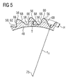
- FIG. 5 An alternative form of the cross-sectional contour 62 of the elevations 56 and depressions 58, which, for example, can be used further downstream in the diffuser channel 42, shows FIG. 5 .
- the contour is in principle approximated to the sinusoidal shape, wherein one of the two flanks 66, which each connects one of the elevation 56 with an adjacent sink 58, is formed steeper than the other of the two flanks 68.
- this shape of the contour 62 is not restrictive, but merely exemplary. Other Contours, even with angular peaks provided contours are conceivable.
- the average radius r m relative to the machine axis 25, shown, to which a maximum height H of the survey 56 and a maximum depth T of the sink 58 is related.
- the mean radius r m is the arithmetic mean of the radius on which the maximum height H is arranged and the radius on which the maximum depth T is arranged.
- the maximum height H or maximum depth T amounts to a maximum of 25% of the channel height KH.
- the invention relates to a ring diffuser 14 for an axial turbomachine, for example for a gas turbine 10, with an outer wall 44 and a coaxial inner wall 48, between which a diffuser channel 42 extends annularly along an axial extension from an inflow-side end 52 diverging to an outflow end 54 wherein the inner wall 48 and the outer wall 44 each comprise a wall surface 46, 50 bounding the diffuser channel 42.
- the invention proposes a wall surface 44, 46 delimiting the diffuser channel 42, which is rotationally asymmetric.
Landscapes
- Engineering & Computer Science (AREA)
- Physics & Mathematics (AREA)
- Fluid Mechanics (AREA)
- Mechanical Engineering (AREA)
- General Engineering & Computer Science (AREA)
- Structures Of Non-Positive Displacement Pumps (AREA)
Priority Applications (14)
| Application Number | Priority Date | Filing Date | Title |
|---|---|---|---|
| EP08021216A EP2194231A1 (fr) | 2008-12-05 | 2008-12-05 | Diffuseur annulaire pour une turbomachine axiale |
| EP11010204.3A EP2455585B1 (fr) | 2008-12-05 | 2009-11-19 | Agencement pour une turbomachine axiale et turbomachine axiale |
| ES09759715T ES2392685T3 (es) | 2008-12-05 | 2009-11-19 | Difusor anular para una turbomáquina axial |
| CN200980148660.1A CN102239312B (zh) | 2008-12-05 | 2009-11-19 | 轴流式涡轮机的环形扩压器、用于轴流式涡轮机的装置和轴流式涡轮机 |
| PL09759715T PL2356320T3 (pl) | 2008-12-05 | 2009-11-19 | Dyfuzor pierścieniowy do osiowej maszyny wirnikowej |
| US13/132,641 US8721272B2 (en) | 2008-12-05 | 2009-11-19 | Ring diffuser for an axial turbomachine |
| EP09759715A EP2356320B1 (fr) | 2008-12-05 | 2009-11-19 | Diffuseur annulaire pour turbomachine axiale |
| JP2011538936A JP5342009B2 (ja) | 2008-12-05 | 2009-11-19 | 軸流ターボ機械のための環状拡散器、軸流ターボ機械のための配列および軸流ターボ機械 |
| CN201210047200.3A CN102536912B (zh) | 2008-12-05 | 2009-11-19 | 用于轴流式涡轮机的环形扩压器、装置和轴流式涡轮机 |
| PCT/EP2009/065445 WO2010063583A1 (fr) | 2008-12-05 | 2009-11-19 | Diffuseur annulaire pour turbomachine axiale |
| RU2011127395/06A RU2485358C2 (ru) | 2008-12-05 | 2009-11-19 | Кольцевой диффузор для осевой турбинной машины, система для осевой турбинной машины, а также осевая турбинная машина |
| US13/351,475 US8721273B2 (en) | 2008-12-05 | 2012-01-17 | Ring diffuser for an axial turbomachine |
| JP2012007773A JP5502114B2 (ja) | 2008-12-05 | 2012-01-18 | 軸流ターボ機械のための環状拡散器、軸流ターボ機械のための配列および軸流ターボ機械 |
| RU2012102538/06A RU2507421C2 (ru) | 2008-12-05 | 2012-01-25 | Кольцевой диффузор для осевой турбинной машины, система для осевой турбинной машины, а также осевая турбинная машина |
Applications Claiming Priority (1)
| Application Number | Priority Date | Filing Date | Title |
|---|---|---|---|
| EP08021216A EP2194231A1 (fr) | 2008-12-05 | 2008-12-05 | Diffuseur annulaire pour une turbomachine axiale |
Publications (1)
| Publication Number | Publication Date |
|---|---|
| EP2194231A1 true EP2194231A1 (fr) | 2010-06-09 |
Family
ID=40602227
Family Applications (3)
| Application Number | Title | Priority Date | Filing Date |
|---|---|---|---|
| EP08021216A Withdrawn EP2194231A1 (fr) | 2008-12-05 | 2008-12-05 | Diffuseur annulaire pour une turbomachine axiale |
| EP11010204.3A Active EP2455585B1 (fr) | 2008-12-05 | 2009-11-19 | Agencement pour une turbomachine axiale et turbomachine axiale |
| EP09759715A Not-in-force EP2356320B1 (fr) | 2008-12-05 | 2009-11-19 | Diffuseur annulaire pour turbomachine axiale |
Family Applications After (2)
| Application Number | Title | Priority Date | Filing Date |
|---|---|---|---|
| EP11010204.3A Active EP2455585B1 (fr) | 2008-12-05 | 2009-11-19 | Agencement pour une turbomachine axiale et turbomachine axiale |
| EP09759715A Not-in-force EP2356320B1 (fr) | 2008-12-05 | 2009-11-19 | Diffuseur annulaire pour turbomachine axiale |
Country Status (8)
| Country | Link |
|---|---|
| US (2) | US8721272B2 (fr) |
| EP (3) | EP2194231A1 (fr) |
| JP (2) | JP5342009B2 (fr) |
| CN (2) | CN102239312B (fr) |
| ES (1) | ES2392685T3 (fr) |
| PL (1) | PL2356320T3 (fr) |
| RU (2) | RU2485358C2 (fr) |
| WO (1) | WO2010063583A1 (fr) |
Cited By (4)
| Publication number | Priority date | Publication date | Assignee | Title |
|---|---|---|---|---|
| CN103781996A (zh) * | 2011-07-22 | 2014-05-07 | 小利兰·斯坦福大学董事会 | 包括具有变化台阶高度的面向后方的台阶的扩散器 |
| EP2837771A1 (fr) | 2013-08-16 | 2015-02-18 | Siemens Aktiengesellschaft | Conception d'un diffuseur axial tenant compte d'éléments intégrés |
| WO2015077067A1 (fr) | 2013-11-21 | 2015-05-28 | United Technologies Corporation | Décalage axisymétrique de parois d'extrémité profilées tridimensionnelles |
| EP2599963A3 (fr) * | 2011-12-02 | 2017-01-11 | United Technologies Corporation | Largeur de virole alternée pour introduire un désaccordage sur des groupes de stator de compresseur |
Families Citing this family (9)
| Publication number | Priority date | Publication date | Assignee | Title |
|---|---|---|---|---|
| EP2381071A1 (fr) * | 2010-04-21 | 2011-10-26 | Siemens Aktiengesellschaft | Diffuseur de gaz d'échappement d'une turbine à gaz |
| DE102012215412A1 (de) | 2012-08-30 | 2014-03-06 | Rolls-Royce Deutschland Ltd & Co Kg | Baugruppe einer Axialturbomaschine und Verfahren zur Herstellung einer solchen Baugruppe |
| DE102012215413B4 (de) | 2012-08-30 | 2020-04-02 | Rolls-Royce Deutschland Ltd & Co Kg | Baugruppe einer Axialturbomaschine |
| JP6483510B2 (ja) * | 2015-04-14 | 2019-03-13 | 三菱日立パワーシステムズ株式会社 | ガスタービンの製造方法 |
| CN104895841B (zh) * | 2015-04-30 | 2018-03-23 | 中国科学院工程热物理研究所 | 整流器、流道结构、组合压气机、航空燃气涡轮发动机 |
| DE102017122524A1 (de) * | 2017-09-28 | 2019-03-28 | Abb Turbo Systems Ag | Diffusor für einen Verdichter |
| CN114607468B (zh) * | 2020-12-09 | 2024-08-02 | 中国航发商用航空发动机有限责任公司 | 冷却气供给结构、冷却方法、涡轮以及燃气涡轮发动机 |
| CN114753895B (zh) * | 2022-03-23 | 2024-08-30 | 中国联合重型燃气轮机技术有限公司 | 排气组件、透平和燃气轮机 |
| DE102022129987B3 (de) | 2022-11-14 | 2024-03-14 | Bayerische Motoren Werke Aktiengesellschaft | Strömungsmaschine, insbesondere für ein Kraftfahrzeug, sowie Kraftfahrzeug mit einer solchen Strömungsmaschine |
Citations (7)
| Publication number | Priority date | Publication date | Assignee | Title |
|---|---|---|---|---|
| US4117671A (en) * | 1976-12-30 | 1978-10-03 | The Boeing Company | Noise suppressing exhaust mixer assembly for ducted-fan, turbojet engine |
| EP0410924A2 (fr) * | 1989-07-25 | 1991-01-30 | United Technologies Corporation | Convertisseur Catalytique |
| GB2281356A (en) * | 1993-08-20 | 1995-03-01 | Rolls Royce Plc | Gas turbine guide vane platform configuration |
| US5592820A (en) * | 1993-10-27 | 1997-01-14 | Societe National D'etdue Et De Construction De Moteurs D'aviation S.N.E.C.M.A | Gas turbine diffuser |
| EP1335136A1 (fr) * | 2002-02-08 | 2003-08-13 | Rolls-Royce Deutschland Ltd & Co KG | Système de guidage du flux traversant le canal d'écoulement d'un compresseur le long des parois de ce canal |
| EP1574667A1 (fr) * | 2004-03-02 | 2005-09-14 | Siemens Aktiengesellschaft | Diffuseur pour compresseur |
| US20080232968A1 (en) * | 2006-02-27 | 2008-09-25 | Honeywell International, Inc. | Non-axisymmetric end wall contouring for a turbomachine blade row |
Family Cites Families (19)
| Publication number | Priority date | Publication date | Assignee | Title |
|---|---|---|---|---|
| US2405723A (en) * | 1946-08-13 | Propulsion apparatus | ||
| US2570155A (en) * | 1948-02-25 | 1951-10-02 | Westinghouse Electric Corp | Flow apparatus |
| US2798661A (en) * | 1954-03-05 | 1957-07-09 | Westinghouse Electric Corp | Gas turbine power plant apparatus |
| US2956400A (en) * | 1957-06-05 | 1960-10-18 | Curtiss Wright Corp | Internal-ribbed exhaust nozzle for jet propulsion devices |
| SU623998A1 (ru) | 1977-03-04 | 1978-09-15 | Центральный научно-исследовательский и проектно-экспериментальный институт промышленных зданий и сооружений | Кольцевой диффузор осевого вентил тора |
| US4167097A (en) * | 1977-09-09 | 1979-09-11 | International Harvester Company | Gas turbine engines with improved compressor-combustor interfaces |
| SU646096A1 (ru) | 1977-09-29 | 1979-02-05 | Предприятие П/Я А-7755 | Осевой диффузор турбомашины |
| SU823654A1 (ru) | 1979-07-05 | 1981-04-23 | Предприятие П/Я М-5641 | Центробежный компрессор |
| DE3023466C2 (de) * | 1980-06-24 | 1982-11-25 | MTU Motoren- und Turbinen-Union München GmbH, 8000 München | Einrichtung zur Verminderung von Sekundärströmungsverlusten in einem beschaufelten Strömungskanal |
| SU1401162A1 (ru) | 1986-06-16 | 1988-06-07 | Предприятие П/Я А-1097 | Осевой диффузор |
| CA1309873C (fr) * | 1987-04-01 | 1992-11-10 | Graham P. Butt | Methode de refroidissement par connection forcee du conduit de transition d'uneturbine a gaz |
| US4971768A (en) * | 1987-11-23 | 1990-11-20 | United Technologies Corporation | Diffuser with convoluted vortex generator |
| DE4428748A1 (de) | 1993-02-20 | 1996-02-15 | Schottel Werft | Wasserstrahlantrieb |
| JP3311526B2 (ja) * | 1994-12-02 | 2002-08-05 | 株式会社日立製作所 | 軸流送風機 |
| CN2613604Y (zh) * | 2003-04-17 | 2004-04-28 | 沈阳黎明航空发动机(集团)有限责任公司 | 一种燃机工艺扩压器 |
| US7690890B2 (en) * | 2004-09-24 | 2010-04-06 | Ishikawajima-Harima Heavy Industries Co. Ltd. | Wall configuration of axial-flow machine, and gas turbine engine |
| US7887297B2 (en) * | 2006-05-02 | 2011-02-15 | United Technologies Corporation | Airfoil array with an endwall protrusion and components of the array |
| DE102006048933A1 (de) | 2006-10-17 | 2008-04-24 | Mtu Aero Engines Gmbh | Anordnung zur Strömungsbeeinflussung |
| JP5283855B2 (ja) * | 2007-03-29 | 2013-09-04 | 株式会社Ihi | ターボ機械の壁、及びターボ機械 |
-
2008
- 2008-12-05 EP EP08021216A patent/EP2194231A1/fr not_active Withdrawn
-
2009
- 2009-11-19 RU RU2011127395/06A patent/RU2485358C2/ru not_active IP Right Cessation
- 2009-11-19 CN CN200980148660.1A patent/CN102239312B/zh not_active Expired - Fee Related
- 2009-11-19 US US13/132,641 patent/US8721272B2/en active Active
- 2009-11-19 JP JP2011538936A patent/JP5342009B2/ja not_active Expired - Fee Related
- 2009-11-19 ES ES09759715T patent/ES2392685T3/es active Active
- 2009-11-19 PL PL09759715T patent/PL2356320T3/pl unknown
- 2009-11-19 EP EP11010204.3A patent/EP2455585B1/fr active Active
- 2009-11-19 EP EP09759715A patent/EP2356320B1/fr not_active Not-in-force
- 2009-11-19 WO PCT/EP2009/065445 patent/WO2010063583A1/fr not_active Ceased
- 2009-11-19 CN CN201210047200.3A patent/CN102536912B/zh active Active
-
2012
- 2012-01-17 US US13/351,475 patent/US8721273B2/en active Active
- 2012-01-18 JP JP2012007773A patent/JP5502114B2/ja not_active Expired - Fee Related
- 2012-01-25 RU RU2012102538/06A patent/RU2507421C2/ru not_active IP Right Cessation
Patent Citations (7)
| Publication number | Priority date | Publication date | Assignee | Title |
|---|---|---|---|---|
| US4117671A (en) * | 1976-12-30 | 1978-10-03 | The Boeing Company | Noise suppressing exhaust mixer assembly for ducted-fan, turbojet engine |
| EP0410924A2 (fr) * | 1989-07-25 | 1991-01-30 | United Technologies Corporation | Convertisseur Catalytique |
| GB2281356A (en) * | 1993-08-20 | 1995-03-01 | Rolls Royce Plc | Gas turbine guide vane platform configuration |
| US5592820A (en) * | 1993-10-27 | 1997-01-14 | Societe National D'etdue Et De Construction De Moteurs D'aviation S.N.E.C.M.A | Gas turbine diffuser |
| EP1335136A1 (fr) * | 2002-02-08 | 2003-08-13 | Rolls-Royce Deutschland Ltd & Co KG | Système de guidage du flux traversant le canal d'écoulement d'un compresseur le long des parois de ce canal |
| EP1574667A1 (fr) * | 2004-03-02 | 2005-09-14 | Siemens Aktiengesellschaft | Diffuseur pour compresseur |
| US20080232968A1 (en) * | 2006-02-27 | 2008-09-25 | Honeywell International, Inc. | Non-axisymmetric end wall contouring for a turbomachine blade row |
Cited By (6)
| Publication number | Priority date | Publication date | Assignee | Title |
|---|---|---|---|---|
| CN103781996A (zh) * | 2011-07-22 | 2014-05-07 | 小利兰·斯坦福大学董事会 | 包括具有变化台阶高度的面向后方的台阶的扩散器 |
| EP2599963A3 (fr) * | 2011-12-02 | 2017-01-11 | United Technologies Corporation | Largeur de virole alternée pour introduire un désaccordage sur des groupes de stator de compresseur |
| EP2837771A1 (fr) | 2013-08-16 | 2015-02-18 | Siemens Aktiengesellschaft | Conception d'un diffuseur axial tenant compte d'éléments intégrés |
| WO2015022269A1 (fr) | 2013-08-16 | 2015-02-19 | Siemens Aktiengesellschaft | Conception d'un diffuseur axial prenant en compte des éléments intégrés |
| WO2015077067A1 (fr) | 2013-11-21 | 2015-05-28 | United Technologies Corporation | Décalage axisymétrique de parois d'extrémité profilées tridimensionnelles |
| EP3071813A4 (fr) * | 2013-11-21 | 2017-07-26 | United Technologies Corporation | Décalage axisymétrique de parois d'extrémité profilées tridimensionnelles |
Also Published As
| Publication number | Publication date |
|---|---|
| RU2011127395A (ru) | 2013-01-10 |
| JP2012072777A (ja) | 2012-04-12 |
| PL2356320T3 (pl) | 2013-02-28 |
| RU2507421C2 (ru) | 2014-02-20 |
| EP2455585B1 (fr) | 2017-03-29 |
| EP2455585A1 (fr) | 2012-05-23 |
| US20120121401A1 (en) | 2012-05-17 |
| US8721273B2 (en) | 2014-05-13 |
| JP2012511115A (ja) | 2012-05-17 |
| CN102536912B (zh) | 2015-07-08 |
| US20110250055A1 (en) | 2011-10-13 |
| EP2356320B1 (fr) | 2012-09-19 |
| CN102239312A (zh) | 2011-11-09 |
| JP5502114B2 (ja) | 2014-05-28 |
| ES2392685T3 (es) | 2012-12-12 |
| US8721272B2 (en) | 2014-05-13 |
| EP2356320A1 (fr) | 2011-08-17 |
| CN102536912A (zh) | 2012-07-04 |
| RU2012102538A (ru) | 2013-07-27 |
| RU2485358C2 (ru) | 2013-06-20 |
| JP5342009B2 (ja) | 2013-11-13 |
| WO2010063583A1 (fr) | 2010-06-10 |
| CN102239312B (zh) | 2014-03-26 |
Similar Documents
| Publication | Publication Date | Title |
|---|---|---|
| EP2356320B1 (fr) | Diffuseur annulaire pour turbomachine axiale | |
| EP0916812B1 (fr) | Etage final pour turbine axial | |
| EP2473743B1 (fr) | Aube mobile de compresseur pour un compresseur axial | |
| EP2378072B1 (fr) | Canal en dérivation d'un turboréacteur | |
| EP2696029B1 (fr) | Grille d'aube avec définition de contour de la paroi latérale et turbomachine | |
| EP2179143B1 (fr) | Refroidissement de fente entre une paroi de chambre de combustion et une paroi de turbine d'une installation de turbine à gaz | |
| EP2746533B1 (fr) | Grille d'aube et turbomachine | |
| DE102015219556A1 (de) | Diffusor für Radialverdichter, Radialverdichter und Turbomaschine mit Radialverdichter | |
| EP0972128A1 (fr) | Structure superficielle pour la paroi d'un canal d'ecoulement ou d'une aube de turbine | |
| DE102010050185B4 (de) | Axialturbomaschine | |
| WO2012084725A1 (fr) | Diffuseur de ventilateur à entrée circulaire et sortie sans symétrie de rotation | |
| EP2304187A1 (fr) | Turbomachine axiale à pertes par jeu réduites | |
| EP2623793A1 (fr) | Grille d'aubes et turbomachine | |
| EP2787172A2 (fr) | Grille d'aubes avec définition de contour de la paroi latérale et turbomachine | |
| EP2561187B1 (fr) | Diffuseur de gaz d'échappement d'une turbine à gaz | |
| EP3064706A1 (fr) | Rangée d'aubes directrices pour une turbomachine traversée axialement | |
| CH709266A2 (de) | Turbinenschaufel und Verfahren zum Auswuchten eines Spitzendeckbandes einer Turbinenschaufel und Gasturbine. | |
| EP2607625B1 (fr) | Turbomachine et étage de turbomachine | |
| EP1766192B1 (fr) | Roue a aubes d'une turbine presentant une aube et au moins un canal refrigerant | |
| EP2597257B1 (fr) | Aubage | |
| WO2016087214A1 (fr) | Aube mobile de turbine, rotor associé et turbomachine | |
| EP2054595A1 (fr) | Boîtier de compresseur | |
| EP3581760B1 (fr) | Pale d'aube pour une turbomachine | |
| EP3164578B1 (fr) | Zone d'évacuation d'une turbine d'un turbocompresseur à gaz d'échappement | |
| EP4090853A1 (fr) | Boîtier pour un ventilateur et ventilateur doté d'un boîtier correspondant |
Legal Events
| Date | Code | Title | Description |
|---|---|---|---|
| PUAI | Public reference made under article 153(3) epc to a published international application that has entered the european phase |
Free format text: ORIGINAL CODE: 0009012 |
|
| AK | Designated contracting states |
Kind code of ref document: A1 Designated state(s): AT BE BG CH CY CZ DE DK EE ES FI FR GB GR HR HU IE IS IT LI LT LU LV MC MT NL NO PL PT RO SE SI SK TR |
|
| AX | Request for extension of the european patent |
Extension state: AL BA MK RS |
|
| AKY | No designation fees paid | ||
| STAA | Information on the status of an ep patent application or granted ep patent |
Free format text: STATUS: THE APPLICATION IS DEEMED TO BE WITHDRAWN |
|
| 18D | Application deemed to be withdrawn |
Effective date: 20101210 |