EP2194237A2 - Kühlsystem für eine Strömungsmaschine - Google Patents
Kühlsystem für eine Strömungsmaschine Download PDFInfo
- Publication number
- EP2194237A2 EP2194237A2 EP20090176597 EP09176597A EP2194237A2 EP 2194237 A2 EP2194237 A2 EP 2194237A2 EP 20090176597 EP20090176597 EP 20090176597 EP 09176597 A EP09176597 A EP 09176597A EP 2194237 A2 EP2194237 A2 EP 2194237A2
- Authority
- EP
- European Patent Office
- Prior art keywords
- compartment
- air
- cooling
- cooling circuit
- supply line
- Prior art date
- Legal status (The legal status is an assumption and is not a legal conclusion. Google has not performed a legal analysis and makes no representation as to the accuracy of the status listed.)
- Granted
Links
- 238000001816 cooling Methods 0.000 title claims abstract description 83
- 239000012809 cooling fluid Substances 0.000 claims abstract description 9
- 239000012530 fluid Substances 0.000 claims abstract description 4
- 238000002485 combustion reaction Methods 0.000 claims description 2
- 239000003570 air Substances 0.000 description 58
- 239000012080 ambient air Substances 0.000 description 11
- 238000010790 dilution Methods 0.000 description 5
- 239000012895 dilution Substances 0.000 description 5
- 230000008901 benefit Effects 0.000 description 4
- 230000003071 parasitic effect Effects 0.000 description 4
- 239000000567 combustion gas Substances 0.000 description 2
- 238000007599 discharging Methods 0.000 description 2
- VNWKTOKETHGBQD-UHFFFAOYSA-N methane Chemical compound C VNWKTOKETHGBQD-UHFFFAOYSA-N 0.000 description 2
- 238000007792 addition Methods 0.000 description 1
- 230000000694 effects Effects 0.000 description 1
- 230000005611 electricity Effects 0.000 description 1
- 239000000446 fuel Substances 0.000 description 1
- 238000009434 installation Methods 0.000 description 1
- 230000002427 irreversible effect Effects 0.000 description 1
- 239000000203 mixture Substances 0.000 description 1
- 238000012986 modification Methods 0.000 description 1
- 230000004048 modification Effects 0.000 description 1
- 239000003345 natural gas Substances 0.000 description 1
- 238000011084 recovery Methods 0.000 description 1
- 230000001629 suppression Effects 0.000 description 1
- 238000011144 upstream manufacturing Methods 0.000 description 1
Images


Classifications
-
- F—MECHANICAL ENGINEERING; LIGHTING; HEATING; WEAPONS; BLASTING
- F01—MACHINES OR ENGINES IN GENERAL; ENGINE PLANTS IN GENERAL; STEAM ENGINES
- F01D—NON-POSITIVE DISPLACEMENT MACHINES OR ENGINES, e.g. STEAM TURBINES
- F01D25/00—Component parts, details, or accessories, not provided for in, or of interest apart from, other groups
- F01D25/08—Cooling; Heating; Heat-insulation
- F01D25/12—Cooling
-
- F—MECHANICAL ENGINEERING; LIGHTING; HEATING; WEAPONS; BLASTING
- F01—MACHINES OR ENGINES IN GENERAL; ENGINE PLANTS IN GENERAL; STEAM ENGINES
- F01D—NON-POSITIVE DISPLACEMENT MACHINES OR ENGINES, e.g. STEAM TURBINES
- F01D25/00—Component parts, details, or accessories, not provided for in, or of interest apart from, other groups
- F01D25/24—Casings; Casing parts, e.g. diaphragms, casing fastenings
-
- F—MECHANICAL ENGINEERING; LIGHTING; HEATING; WEAPONS; BLASTING
- F01—MACHINES OR ENGINES IN GENERAL; ENGINE PLANTS IN GENERAL; STEAM ENGINES
- F01D—NON-POSITIVE DISPLACEMENT MACHINES OR ENGINES, e.g. STEAM TURBINES
- F01D25/00—Component parts, details, or accessories, not provided for in, or of interest apart from, other groups
- F01D25/30—Exhaust heads, chambers, or the like
-
- F—MECHANICAL ENGINEERING; LIGHTING; HEATING; WEAPONS; BLASTING
- F02—COMBUSTION ENGINES; HOT-GAS OR COMBUSTION-PRODUCT ENGINE PLANTS
- F02C—GAS-TURBINE PLANTS; AIR INTAKES FOR JET-PROPULSION PLANTS; CONTROLLING FUEL SUPPLY IN AIR-BREATHING JET-PROPULSION PLANTS
- F02C7/00—Features, components parts, details or accessories, not provided for in, or of interest apart form groups F02C1/00 - F02C6/00; Air intakes for jet-propulsion plants
- F02C7/12—Cooling of plants
- F02C7/16—Cooling of plants characterised by cooling medium
- F02C7/18—Cooling of plants characterised by cooling medium the medium being gaseous, e.g. air
-
- F—MECHANICAL ENGINEERING; LIGHTING; HEATING; WEAPONS; BLASTING
- F05—INDEXING SCHEMES RELATING TO ENGINES OR PUMPS IN VARIOUS SUBCLASSES OF CLASSES F01-F04
- F05D—INDEXING SCHEME FOR ASPECTS RELATING TO NON-POSITIVE-DISPLACEMENT MACHINES OR ENGINES, GAS-TURBINES OR JET-PROPULSION PLANTS
- F05D2260/00—Function
- F05D2260/20—Heat transfer, e.g. cooling
- F05D2260/205—Cooling fluid recirculation, i.e. after cooling one or more components is the cooling fluid recovered and used elsewhere for other purposes
-
- F—MECHANICAL ENGINEERING; LIGHTING; HEATING; WEAPONS; BLASTING
- F05—INDEXING SCHEMES RELATING TO ENGINES OR PUMPS IN VARIOUS SUBCLASSES OF CLASSES F01-F04
- F05D—INDEXING SCHEME FOR ASPECTS RELATING TO NON-POSITIVE-DISPLACEMENT MACHINES OR ENGINES, GAS-TURBINES OR JET-PROPULSION PLANTS
- F05D2260/00—Function
- F05D2260/60—Fluid transfer
- F05D2260/608—Aeration, ventilation, dehumidification or moisture removal of closed spaces
-
- Y—GENERAL TAGGING OF NEW TECHNOLOGICAL DEVELOPMENTS; GENERAL TAGGING OF CROSS-SECTIONAL TECHNOLOGIES SPANNING OVER SEVERAL SECTIONS OF THE IPC; TECHNICAL SUBJECTS COVERED BY FORMER USPC CROSS-REFERENCE ART COLLECTIONS [XRACs] AND DIGESTS
- Y02—TECHNOLOGIES OR APPLICATIONS FOR MITIGATION OR ADAPTATION AGAINST CLIMATE CHANGE
- Y02E—REDUCTION OF GREENHOUSE GAS [GHG] EMISSIONS, RELATED TO ENERGY GENERATION, TRANSMISSION OR DISTRIBUTION
- Y02E20/00—Combustion technologies with mitigation potential
- Y02E20/16—Combined cycle power plant [CCPP], or combined cycle gas turbine [CCGT]
Definitions
- the present invention relates generally to a cooling system for a turbomachine; more specifically, but not by way of limitation, to an integrated cooling system that requires less energy to operate.
- Figures 1A and 1B collectively Figure 1 , is a schematic illustrating known independent cooling systems for a turbomachine.
- Figure 1 illustrates a turbomachine 100, a heat recovery steam generator (HRSG) 115, and a stack 120.
- HRSG heat recovery steam generator
- the turbomachine 100 may comprise multiple compartments, which enclose the components of the turbomachine 100.
- Figure 1 illustrates two of the multiple compartments: a first compartment 105 and a second compartment 110.
- the present invention is described with repeated references to the first compartment 105 and the second compartment 110, the present invention is not limited to the first compartment 105 and second compartment 110.
- an embodiment of the present invention may be adapted to each of the multiple compartments, some of which may not be illustrated in the Figures.
- the first compartment 105 may enclose a compressor section 125 which drawings in ambient air, illustrates by an arrow.
- the ambient air enters the compressor section 125, is compressed and then discharged to a combustion system 130, where a fuel, such as a natural gas, is burned to provide high-energy combustion gases; which drives a turbine section 140.
- a fuel such as a natural gas
- the turbine section 140 the energy of the combustion gases is converted into work, some of which is used to drive the compressor section 125. with the remainder available to drive a load such as, but not limiting of, a generator (not illustrated). While the turbomachine 100 operates, these components emit heat that raises the temperature of the environment enclosed by the first compartment 105.
- the first compartment 105 may also include a first compartment (FC) cooling circuit 155, which serves to lower the temperature of the environment within the first compartment 105.
- FC cooling circuit 155 may comprise a FC air circulation device 160, a FC supply line 165, and a FC discharge line 170.
- FC air circulation device 160 may comprise at least one fan.
- the FC cooling circuit 155 may draw in air that derives from the ambient. For example, but not limiting of, the air may flow directly from the ambient; or the air may flow from a ducting system that conditions the air, which originates from the ambient.
- the FC cooling circuit 155 may move the ambient air through the FC supply line 165 into the first compartment 105.
- the ambient air becomes heated, as some of the heat from the first compartment 105 is removed.
- the heated air is discharged to the atmosphere via the FC discharge line 170.
- the FC cooling circuit 155 draws in ambient air, removes heat from the first compartment 105. This heated air may then be discharged to atmosphere at 200 degrees Fahrenheit or greater.
- the second compartment 110 may enclose an exhaust frame 145, which generally serves to move the exhaust generated by the turbomachine 100 towards an HRSG 115.
- the exhaust frame 145 channels the exhaust that flows from the turbine section 140 to the HRSG 115 via a shell.
- An embodiment of the shell comprises a double wall 150.
- the double wall 150 may comprise a circular annulus that surrounds the exhaust frame 145, as illustrated in Figure 1B .
- An alternate embodiment of the shell may comprise a single shell, wherein the single wall may comprise cooling holes and/or a serpentine cooling path for cooling the exhaust frame 145.
- the second compartment 110 may also include a second compartment (SC) cooling circuit 175, which serves to lower the temperature of the environment within the second compartment 110.
- An embodiment of the SC cooling circuit 175 may comprise a SC air circulation device 180, and a SC supply line 185.
- An embodiment of the SC air circulation device 180 may comprise at least one blower.
- the SC cooling circuit 175 may draw in ambient air, then move the ambient air through the SC supply line 185 into the double wall 150.
- the ambient air serves to cool the exhaust frame 145, which is heated by the exhaust flowing therein.
- the ambient air becomes heated and is discharged to the HRSG 115 where the heated air mixes with the exhaust.
- the SC cooling circuit 175 draws in ambient air which may become heated to 350 degrees Fahrenheit or greater. This heated air is then mixed with the exhaust that may be at a temperature of 1150 degrees Fahrenheit or greater.
- FC air circulation device 160 and SC air circulation device 180 typically require electricity to operate.
- the devices 160,180 may be considered parasitic loads on the turbomachine 100.
- parasitic loads consume a portion of the energy generate by the turbomachine leading to a reduction in the overall efficiency.
- temperature dilution occurs when relatively cooler air discharging from the double wall 150 mixes with the significantly hotter exhaust discharging from the internal portions of the exhaust frame 145. Temperature dilution may be considered an irreversible energy loss, which leads to less energy available for the bottoming cycle of the HRSG 115. This temperature dilution may cause an approximately 10 to 20 degree temperature suppression, leading to a decrease in the efficiency of the turbomachine 100 and the HRSG 115.
- the system should integrate the cooling of multiple turbomachine compartments.
- the system should also reduce the amount of parasitic loads on the turbomachine.
- the system should also decrease the effect of temperature dilution.
- a system for cooling multiple compartments of a turbomachine comprising: a turbomachine comprising multiple compartments, wherein the compartments comprise at least a first compartment and a second compartment; a cooling system for reducing a temperature of each compartment of the multiple compartments; wherein the cooling system comprises: a cooling circuit which is in fluid communication with at least the first compartment and the second compartment; wherein a first portion the cooling circuit is located within the first compartment and a second portion of the cooling circuit is located within the second compartment; at least one air circulation device for moving a cooling fluid through the cooling circuit; wherein the cooling fluid comprises air which derives from ambient, wherein an air enters the first compartment at a first temperature range, exits the first compartment at a second temperature range and then enters the second compartment at the second temperature range and exits the second compartment at a third temperature range.
- Cooling systems in accordance with embodiments of the present invention, may provide the following benefits to the user. Improvement on the combined cycle efficiency and an increase in the power output. This may result from reducing the exhaust dilution losses and reducing the parasitic load by requiring fewer air circulation devices.
- the present invention may also benefit the user by reducing the installation and start-up costs of the cooling system by requiring fewer air circulation devices and integrating the cooling systems.
- the present invention may circulate a cooling fluid through an integrated cooling circuit, which may be in fluid communication with each compartment of the multiple compartment of the turbomachine 100.
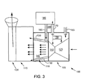
- Figure 2 and 3 are schematic illustrating integrated cooling systems.
- the discussions of Figures 2 and 3 will be limited to the respective inventions; other illustrated elements may be similar to the discussion of Figure 1 .
- FIG. 2 is a schematic illustrating an integrated cooling system for a turbomachine 100, in accordance with an embodiment of the present invention.
- This embodiment of the present invention may utilize a first integrated cooling circuit 200 to cool the first compartment 105 and the second compartment 110.
- An embodiment of the first integrated cooling circuit 200 may comprise: the FC air circulation device 160, the FC supply line 165, the FC discharge line 170, the SC supply line 185, and a compartment link 205.
- An embodiment of the first integrated cooling circuit 200 serves to integrate the FC cooling circuit 155 and the SC cooling circuit 175 into one circuit. This may provide a more efficient and simultaneous cooling of the first compartment 105 and the second compartment 110.
- the cooling compartment link 205 allows for the discharge of the heated air to serve as a cooling fluid for the exhaust frame 145. This may be accomplished by, for example, but not limiting of, connecting a discharge end of the FC discharge line 170 with a first end of the cooling compartment link 205. Next a second end of the cooling compartment link 205 may be connected to a supply end of the SC supply line 185.
- an embodiment of the first integrated cooling circuit 200 may operate as follows.
- the FC air circulation device 160 may draw-in air from the ambient. This ambient air may be pressurized and discharged via the FC supply line 165 into the first compartment 105. The warm air may then exit the first compartment 105, via the FC discharge line 170, and flow through the cooling compartment link 205 to the SC supply line 185. The warm air may then flow through the double wall 150 to cooling the exhaust frame 145. Here, the air is heated again and exits the exhaust frame 145 to mix with the exhaust.
- the FC air circulation device 160 may drawn in air from the ambient.
- the air may enter the first compartment 105 at a temperature of approximately 90 degrees Fahrenheit.
- the temperature of the air is increased as heat is removed from the first compartment 105 by the air.
- the air may exit the first compartment 105 at a temperature of approximately 300 degrees Fahrenheit.
- the air may this enter the double wall 150 at a temperature of approximately 300 degrees Fahrenheit, which is significantly highly than air at an ambient temperature.
- the air is heated again as the exhaust frame 145 is cooled.
- the air may exit the double wall 150 at a temperature of approximately 360 degrees Fahrenheit.
- the air may then mix with the exhaust, which may have a temperature of approximately 1200 degrees Fahrenheit. This may increase the effective exhaust temperature, which may lead to higher output and efficiency of the HRSG 115.
- the FC air circulation device 160 may be integrated on the FC discharge line 170.
- the FC air circulation device 160 may induce the circulation of the air within the first compartment 105.
- a bypass line 210 may be integrated therein.
- the cooling flow required may be lower than the flowrate provided by the first integrated cooling circuit 200.
- the bypass line 210 may remove a portion of the air within the first integrated cooling circuit 200.
- An embodiment of the bypass line 210 may vent the excess air to the atmosphere.
- a booster device 215 may be integrated therein. Depending on the required delivery pressure of the air to the exhaust frame 145, a booster device 215 may be required. The booster device 215 may be configured for increasing the pressure. The booster device 215 may comprise a blower, or the like. The size of the booster device 215 may be significantly smaller than and consume less energy than the SC air circulation device 180, previously described.
- FIG. 3 is a schematic illustrating an integrated cooling system for a turbomachine, in accordance with an alternate embodiment of the present invention.
- This embodiment of the present invention may utilize a second integrated cooling circuit 300 to cool the first compartment 105 and the second compartment 110.
- An embodiment of the second integrated cooling circuit 300 may comprise: the FC supply line 165, the FC discharge line 170, the SC air circulation device 180, and the SC supply line 185.
- An embodiment of the second integrated cooling circuit 300 serves to integrate the FC cooling circuit 155 and the SC cooling circuit 175 into one circuit. This may provide a more efficient and simultaneous cooling of the first compartment 105 and the second compartment 110.
- the SC air circulation device 180 may link the first compartment 105 and the second compartment 110.
- the SC air circulation device 180 may allow for the discharge of the heated air of the first compartment 105 to serve as a cooling fluid for the exhaust frame 145. This may be accomplished by, for example, but not limiting of, connecting a discharge end of the FC discharge line 170 to an inlet portion of the SC air circulation device 180. Next a discharge portion of the SC air circulation device 180 may be connected to a supply end of the SC supply line 185.
- an embodiment of the second integrated cooling circuit 300 may operate as follows.
- the SC air circulation device 180 may draw air from the ambient.
- the air may enter the first compartment 105 via the FC supply line 165.
- the warm air may then exit the first compartment 105 via the FC discharge line 170.
- the warm air may be pressurized by the SC air circulation device 180 and discharged, via the SC supply line 185, into the double wall 150 to cooling the exhaust frame 145.
- the air is heated again and exits the exhaust frame 145 to mix with the exhaust.
Landscapes
- Engineering & Computer Science (AREA)
- Mechanical Engineering (AREA)
- General Engineering & Computer Science (AREA)
- Chemical & Material Sciences (AREA)
- Combustion & Propulsion (AREA)
- Structures Of Non-Positive Displacement Pumps (AREA)
- Engine Equipment That Uses Special Cycles (AREA)
Applications Claiming Priority (1)
| Application Number | Priority Date | Filing Date | Title |
|---|---|---|---|
| US12/327,356 US8100632B2 (en) | 2008-12-03 | 2008-12-03 | Cooling system for a turbomachine |
Publications (3)
| Publication Number | Publication Date |
|---|---|
| EP2194237A2 true EP2194237A2 (de) | 2010-06-09 |
| EP2194237A3 EP2194237A3 (de) | 2015-05-27 |
| EP2194237B1 EP2194237B1 (de) | 2017-10-25 |
Family
ID=41376356
Family Applications (1)
| Application Number | Title | Priority Date | Filing Date |
|---|---|---|---|
| EP09176597.4A Not-in-force EP2194237B1 (de) | 2008-12-03 | 2009-11-20 | Kühlsystem für eine Strömungsmaschine |
Country Status (4)
| Country | Link |
|---|---|
| US (1) | US8100632B2 (de) |
| EP (1) | EP2194237B1 (de) |
| JP (1) | JP2010133408A (de) |
| CN (1) | CN101749120B (de) |
Cited By (2)
| Publication number | Priority date | Publication date | Assignee | Title |
|---|---|---|---|---|
| EP2955100A1 (de) * | 2014-06-06 | 2015-12-16 | Rolls-Royce plc | Kanalanordnung für einen verbrennungsmotor |
| IT202300003156A1 (it) * | 2023-02-23 | 2024-08-23 | Nuovo Pignone Tecnologie Srl | Sistema di ventilazione di un complesso di turbina a gas e metodo per la ventilazione di un complesso di turbina a gas |
Families Citing this family (7)
| Publication number | Priority date | Publication date | Assignee | Title |
|---|---|---|---|---|
| US9784185B2 (en) * | 2012-04-26 | 2017-10-10 | General Electric Company | System and method for cooling a gas turbine with an exhaust gas provided by the gas turbine |
| CN104948286B (zh) * | 2014-03-27 | 2018-01-09 | 中国航发商用航空发动机有限责任公司 | 发动机核心舱的冷却方法及冷却装置 |
| FR3021350B1 (fr) * | 2014-05-20 | 2016-07-01 | Snecma | Procede de detection de fuite de fluide dans une turbomachine et systeme de distribution de fluide |
| US10502137B2 (en) | 2015-10-19 | 2019-12-10 | General Electric Company | Gas turbine with a valve cooling system |
| CN105840314B (zh) * | 2016-04-26 | 2017-09-19 | 中科合肥微小型燃气轮机研究院有限责任公司 | 带储热功能的燃气轮机试验台排气系统 |
| JP6894358B2 (ja) * | 2017-11-30 | 2021-06-30 | 三菱パワー株式会社 | 排気ダクト |
| JP7492417B2 (ja) * | 2020-09-25 | 2024-05-29 | 三菱重工業株式会社 | ガスタービンの車室の冷却装置、ガスタービン及びガスタービンの車室の冷却方法 |
Family Cites Families (20)
| Publication number | Priority date | Publication date | Assignee | Title |
|---|---|---|---|---|
| DE768041C (de) * | 1940-12-14 | 1955-05-26 | Messerschmitt Boelkow Blohm | Heissstrahltriebwerk, insbesondere zum Vortrieb von Luftfahrzeugen |
| US2940257A (en) * | 1953-03-27 | 1960-06-14 | Daimler Benz Ag | Cooling arrangement for a combustion turbine |
| US3015937A (en) * | 1958-07-03 | 1962-01-09 | James V Giliberty | Temperature modulating system for internal combustion turbines and the like |
| US3631672A (en) * | 1969-08-04 | 1972-01-04 | Gen Electric | Eductor cooled gas turbine casing |
| JPS59173527A (ja) * | 1983-03-22 | 1984-10-01 | Hitachi Ltd | ガスタ−ビン排気フレ−ム冷却空気系統 |
| US4991391A (en) * | 1989-01-27 | 1991-02-12 | Westinghouse Electric Corp. | System for cooling in a gas turbine |
| JP2515535Y2 (ja) * | 1991-08-03 | 1996-10-30 | 川崎重工業株式会社 | 発電機室の換気装置 |
| JPH06193464A (ja) * | 1992-12-24 | 1994-07-12 | Hitachi Ltd | ガスタービン高効率排熱回収発電設備 |
| JP3346830B2 (ja) * | 1993-05-31 | 2002-11-18 | 東芝エンジニアリング株式会社 | ガスタービンエンクロージャー換気装置 |
| US5593274A (en) * | 1995-03-31 | 1997-01-14 | General Electric Co. | Closed or open circuit cooling of turbine rotor components |
| US5649418A (en) * | 1995-08-07 | 1997-07-22 | Solar Turbines Incorporated | Integrated power converter cooling system using turbine intake air |
| US6098395A (en) * | 1996-04-04 | 2000-08-08 | Siemens Westinghouse Power Corporation | Closed-loop air cooling system for a turbine engine |
| US5782076A (en) * | 1996-05-17 | 1998-07-21 | Westinghouse Electric Corporation | Closed loop air cooling system for combustion turbines |
| US5829245A (en) * | 1996-12-31 | 1998-11-03 | Westinghouse Electric Corporation | Cooling system for gas turbine vane |
| US6250061B1 (en) * | 1999-03-02 | 2001-06-26 | General Electric Company | Compressor system and methods for reducing cooling airflow |
| US6398486B1 (en) * | 2000-06-01 | 2002-06-04 | General Electric Company | Steam exit flow design for aft cavities of an airfoil |
| JP3899916B2 (ja) * | 2001-12-07 | 2007-03-28 | 石川島播磨重工業株式会社 | ガスタービン換気装置 |
| US6638013B2 (en) * | 2002-02-25 | 2003-10-28 | Honeywell International Inc. | Thermally isolated housing in gas turbine engine |
| US6986253B2 (en) * | 2003-07-16 | 2006-01-17 | General Electric Company | Methods and apparatus for cooling gas turbine engine combustors |
| US7743613B2 (en) * | 2006-11-10 | 2010-06-29 | General Electric Company | Compound turbine cooled engine |
-
2008
- 2008-12-03 US US12/327,356 patent/US8100632B2/en not_active Expired - Fee Related
-
2009
- 2009-11-20 EP EP09176597.4A patent/EP2194237B1/de not_active Not-in-force
- 2009-12-01 JP JP2009273092A patent/JP2010133408A/ja active Pending
- 2009-12-01 CN CN2009102538963A patent/CN101749120B/zh not_active Expired - Fee Related
Cited By (4)
| Publication number | Priority date | Publication date | Assignee | Title |
|---|---|---|---|---|
| EP2955100A1 (de) * | 2014-06-06 | 2015-12-16 | Rolls-Royce plc | Kanalanordnung für einen verbrennungsmotor |
| US9670820B2 (en) | 2014-06-06 | 2017-06-06 | Rolls-Royce Plc | Duct arrangement for an internal combustion engine |
| IT202300003156A1 (it) * | 2023-02-23 | 2024-08-23 | Nuovo Pignone Tecnologie Srl | Sistema di ventilazione di un complesso di turbina a gas e metodo per la ventilazione di un complesso di turbina a gas |
| WO2024175253A1 (en) * | 2023-02-23 | 2024-08-29 | Nuovo Pignone Tecnologie - S.R.L. | A gas turbine package ventilation system and a method for ventilating a gas turbine package |
Also Published As
| Publication number | Publication date |
|---|---|
| CN101749120A (zh) | 2010-06-23 |
| CN101749120B (zh) | 2013-05-08 |
| US8100632B2 (en) | 2012-01-24 |
| JP2010133408A (ja) | 2010-06-17 |
| US20100135776A1 (en) | 2010-06-03 |
| EP2194237A3 (de) | 2015-05-27 |
| EP2194237B1 (de) | 2017-10-25 |
Similar Documents
| Publication | Publication Date | Title |
|---|---|---|
| EP2194237B1 (de) | Kühlsystem für eine Strömungsmaschine | |
| US10995670B2 (en) | Gas turbine energy supplementing systems and heating systems, and methods of making and using the same | |
| US6389793B1 (en) | Combustion turbine cooling media supply system and related method | |
| US7836680B2 (en) | Aircraft combination engines thermal management system | |
| US7337605B2 (en) | Thermal management for aircraft auxiliary power unit compartment | |
| CN106715840B (zh) | 动力生成系统及用于生成动力的方法 | |
| EP1484489B1 (de) | Einlassluftkühlsystem für eine Gasturbine | |
| CA2991449C (en) | Heat exchanger assembly for engine bleed air | |
| CN102939679B (zh) | 具有设置在外壳内的燃料电池的燃料电池系统 | |
| US20130036722A1 (en) | Fuel system having fuel control unit and heat exchanger | |
| EP2825757B1 (de) | Pumpensystem mit konstanter drehzahl für ein motorwärmeverwaltungssystem, zur luft-ölkühler-verringerung und zur verlusteliminierung eines klimaregelungssystems | |
| CN102224027A (zh) | 中间冷却器和后冷却器的低温燃料冷却 | |
| US20020148214A1 (en) | Gas turbine | |
| JP2000257446A (ja) | 冷却空気流圧縮機装置、タービン・エンジン及び冷却空気流を減らす方法 | |
| US5287694A (en) | Fluid channeling system | |
| CN1379170A (zh) | 燃气轮机 | |
| CN103256120A (zh) | 具有固态热泵的燃气涡轮机进气口系统 | |
| RU2347091C1 (ru) | Газотурбинный двигатель | |
| EP1528239B1 (de) | Vorrichtung zum Betrieb von Gasturbinen mit Verdichterzwischenkühlern | |
| CA2383429C (en) | Method and device for increasing the pressure of a gas | |
| CA2453634C (en) | Turbo recuperator device | |
| CN107013337A (zh) | 具有阀冷却系统的燃气涡轮 | |
| US20100107649A1 (en) | Gas Turbine Engine With Fuel Booster | |
| RU2238418C2 (ru) | Двухконтурный газотурбинный двигатель | |
| EP4663918A1 (de) | Wärmeverwaltungssystem für lüfterausgangsleitschaufeln für hybride elektrizität |
Legal Events
| Date | Code | Title | Description |
|---|---|---|---|
| PUAI | Public reference made under article 153(3) epc to a published international application that has entered the european phase |
Free format text: ORIGINAL CODE: 0009012 |
|
| AK | Designated contracting states |
Kind code of ref document: A2 Designated state(s): AT BE BG CH CY CZ DE DK EE ES FI FR GB GR HR HU IE IS IT LI LT LU LV MC MK MT NL NO PL PT RO SE SI SK SM TR |
|
| AX | Request for extension of the european patent |
Extension state: AL BA RS |
|
| PUAL | Search report despatched |
Free format text: ORIGINAL CODE: 0009013 |
|
| AK | Designated contracting states |
Kind code of ref document: A3 Designated state(s): AT BE BG CH CY CZ DE DK EE ES FI FR GB GR HR HU IE IS IT LI LT LU LV MC MK MT NL NO PL PT RO SE SI SK SM TR |
|
| AX | Request for extension of the european patent |
Extension state: AL BA RS |
|
| RIC1 | Information provided on ipc code assigned before grant |
Ipc: F01D 25/30 20060101ALI20150422BHEP Ipc: F02C 7/18 20060101ALI20150422BHEP Ipc: F01D 25/12 20060101AFI20150422BHEP |
|
| 17P | Request for examination filed |
Effective date: 20151127 |
|
| RBV | Designated contracting states (corrected) |
Designated state(s): AT BE BG CH CY CZ DE DK EE ES FI FR GB GR HR HU IE IS IT LI LT LU LV MC MK MT NL NO PL PT RO SE SI SK SM TR |
|
| 17Q | First examination report despatched |
Effective date: 20160203 |
|
| GRAP | Despatch of communication of intention to grant a patent |
Free format text: ORIGINAL CODE: EPIDOSNIGR1 |
|
| INTG | Intention to grant announced |
Effective date: 20170515 |
|
| GRAS | Grant fee paid |
Free format text: ORIGINAL CODE: EPIDOSNIGR3 |
|
| GRAA | (expected) grant |
Free format text: ORIGINAL CODE: 0009210 |
|
| AK | Designated contracting states |
Kind code of ref document: B1 Designated state(s): AT BE BG CH CY CZ DE DK EE ES FI FR GB GR HR HU IE IS IT LI LT LU LV MC MK MT NL NO PL PT RO SE SI SK SM TR |
|
| REG | Reference to a national code |
Ref country code: GB Ref legal event code: FG4D |
|
| REG | Reference to a national code |
Ref country code: CH Ref legal event code: EP |
|
| REG | Reference to a national code |
Ref country code: AT Ref legal event code: REF Ref document number: 940163 Country of ref document: AT Kind code of ref document: T Effective date: 20171115 |
|
| REG | Reference to a national code |
Ref country code: FR Ref legal event code: PLFP Year of fee payment: 9 |
|
| REG | Reference to a national code |
Ref country code: IE Ref legal event code: FG4D |
|
| REG | Reference to a national code |
Ref country code: DE Ref legal event code: R096 Ref document number: 602009048993 Country of ref document: DE |
|
| REG | Reference to a national code |
Ref country code: NL Ref legal event code: MP Effective date: 20171025 |
|
| REG | Reference to a national code |
Ref country code: LT Ref legal event code: MG4D |
|
| REG | Reference to a national code |
Ref country code: AT Ref legal event code: MK05 Ref document number: 940163 Country of ref document: AT Kind code of ref document: T Effective date: 20171025 |
|
| PG25 | Lapsed in a contracting state [announced via postgrant information from national office to epo] |
Ref country code: NL Free format text: LAPSE BECAUSE OF FAILURE TO SUBMIT A TRANSLATION OF THE DESCRIPTION OR TO PAY THE FEE WITHIN THE PRESCRIBED TIME-LIMIT Effective date: 20171025 |
|
| PG25 | Lapsed in a contracting state [announced via postgrant information from national office to epo] |
Ref country code: NO Free format text: LAPSE BECAUSE OF FAILURE TO SUBMIT A TRANSLATION OF THE DESCRIPTION OR TO PAY THE FEE WITHIN THE PRESCRIBED TIME-LIMIT Effective date: 20180125 Ref country code: ES Free format text: LAPSE BECAUSE OF FAILURE TO SUBMIT A TRANSLATION OF THE DESCRIPTION OR TO PAY THE FEE WITHIN THE PRESCRIBED TIME-LIMIT Effective date: 20171025 Ref country code: LT Free format text: LAPSE BECAUSE OF FAILURE TO SUBMIT A TRANSLATION OF THE DESCRIPTION OR TO PAY THE FEE WITHIN THE PRESCRIBED TIME-LIMIT Effective date: 20171025 Ref country code: FI Free format text: LAPSE BECAUSE OF FAILURE TO SUBMIT A TRANSLATION OF THE DESCRIPTION OR TO PAY THE FEE WITHIN THE PRESCRIBED TIME-LIMIT Effective date: 20171025 Ref country code: SE Free format text: LAPSE BECAUSE OF FAILURE TO SUBMIT A TRANSLATION OF THE DESCRIPTION OR TO PAY THE FEE WITHIN THE PRESCRIBED TIME-LIMIT Effective date: 20171025 |
|
| PG25 | Lapsed in a contracting state [announced via postgrant information from national office to epo] |
Ref country code: GR Free format text: LAPSE BECAUSE OF FAILURE TO SUBMIT A TRANSLATION OF THE DESCRIPTION OR TO PAY THE FEE WITHIN THE PRESCRIBED TIME-LIMIT Effective date: 20180126 Ref country code: AT Free format text: LAPSE BECAUSE OF FAILURE TO SUBMIT A TRANSLATION OF THE DESCRIPTION OR TO PAY THE FEE WITHIN THE PRESCRIBED TIME-LIMIT Effective date: 20171025 Ref country code: IS Free format text: LAPSE BECAUSE OF FAILURE TO SUBMIT A TRANSLATION OF THE DESCRIPTION OR TO PAY THE FEE WITHIN THE PRESCRIBED TIME-LIMIT Effective date: 20180225 Ref country code: HR Free format text: LAPSE BECAUSE OF FAILURE TO SUBMIT A TRANSLATION OF THE DESCRIPTION OR TO PAY THE FEE WITHIN THE PRESCRIBED TIME-LIMIT Effective date: 20171025 Ref country code: LV Free format text: LAPSE BECAUSE OF FAILURE TO SUBMIT A TRANSLATION OF THE DESCRIPTION OR TO PAY THE FEE WITHIN THE PRESCRIBED TIME-LIMIT Effective date: 20171025 Ref country code: BG Free format text: LAPSE BECAUSE OF FAILURE TO SUBMIT A TRANSLATION OF THE DESCRIPTION OR TO PAY THE FEE WITHIN THE PRESCRIBED TIME-LIMIT Effective date: 20180125 |
|
| REG | Reference to a national code |
Ref country code: DE Ref legal event code: R097 Ref document number: 602009048993 Country of ref document: DE |
|
| PG25 | Lapsed in a contracting state [announced via postgrant information from national office to epo] |
Ref country code: CH Free format text: LAPSE BECAUSE OF NON-PAYMENT OF DUE FEES Effective date: 20171130 Ref country code: CZ Free format text: LAPSE BECAUSE OF FAILURE TO SUBMIT A TRANSLATION OF THE DESCRIPTION OR TO PAY THE FEE WITHIN THE PRESCRIBED TIME-LIMIT Effective date: 20171025 Ref country code: MC Free format text: LAPSE BECAUSE OF FAILURE TO SUBMIT A TRANSLATION OF THE DESCRIPTION OR TO PAY THE FEE WITHIN THE PRESCRIBED TIME-LIMIT Effective date: 20171025 Ref country code: SK Free format text: LAPSE BECAUSE OF FAILURE TO SUBMIT A TRANSLATION OF THE DESCRIPTION OR TO PAY THE FEE WITHIN THE PRESCRIBED TIME-LIMIT Effective date: 20171025 Ref country code: CY Free format text: LAPSE BECAUSE OF FAILURE TO SUBMIT A TRANSLATION OF THE DESCRIPTION OR TO PAY THE FEE WITHIN THE PRESCRIBED TIME-LIMIT Effective date: 20171025 Ref country code: DK Free format text: LAPSE BECAUSE OF FAILURE TO SUBMIT A TRANSLATION OF THE DESCRIPTION OR TO PAY THE FEE WITHIN THE PRESCRIBED TIME-LIMIT Effective date: 20171025 Ref country code: LI Free format text: LAPSE BECAUSE OF NON-PAYMENT OF DUE FEES Effective date: 20171130 Ref country code: EE Free format text: LAPSE BECAUSE OF FAILURE TO SUBMIT A TRANSLATION OF THE DESCRIPTION OR TO PAY THE FEE WITHIN THE PRESCRIBED TIME-LIMIT Effective date: 20171025 |
|
| PG25 | Lapsed in a contracting state [announced via postgrant information from national office to epo] |
Ref country code: IT Free format text: LAPSE BECAUSE OF FAILURE TO SUBMIT A TRANSLATION OF THE DESCRIPTION OR TO PAY THE FEE WITHIN THE PRESCRIBED TIME-LIMIT Effective date: 20171025 Ref country code: RO Free format text: LAPSE BECAUSE OF FAILURE TO SUBMIT A TRANSLATION OF THE DESCRIPTION OR TO PAY THE FEE WITHIN THE PRESCRIBED TIME-LIMIT Effective date: 20171025 Ref country code: PL Free format text: LAPSE BECAUSE OF FAILURE TO SUBMIT A TRANSLATION OF THE DESCRIPTION OR TO PAY THE FEE WITHIN THE PRESCRIBED TIME-LIMIT Effective date: 20171025 Ref country code: LU Free format text: LAPSE BECAUSE OF NON-PAYMENT OF DUE FEES Effective date: 20171120 Ref country code: SM Free format text: LAPSE BECAUSE OF FAILURE TO SUBMIT A TRANSLATION OF THE DESCRIPTION OR TO PAY THE FEE WITHIN THE PRESCRIBED TIME-LIMIT Effective date: 20171025 |
|
| PLBE | No opposition filed within time limit |
Free format text: ORIGINAL CODE: 0009261 |
|
| REG | Reference to a national code |
Ref country code: BE Ref legal event code: MM Effective date: 20171130 |
|
| STAA | Information on the status of an ep patent application or granted ep patent |
Free format text: STATUS: NO OPPOSITION FILED WITHIN TIME LIMIT |
|
| REG | Reference to a national code |
Ref country code: IE Ref legal event code: MM4A |
|
| GBPC | Gb: european patent ceased through non-payment of renewal fee |
Effective date: 20180125 |
|
| PG25 | Lapsed in a contracting state [announced via postgrant information from national office to epo] |
Ref country code: MT Free format text: LAPSE BECAUSE OF NON-PAYMENT OF DUE FEES Effective date: 20171120 |
|
| 26N | No opposition filed |
Effective date: 20180726 |
|
| REG | Reference to a national code |
Ref country code: FR Ref legal event code: PLFP Year of fee payment: 10 |
|
| PG25 | Lapsed in a contracting state [announced via postgrant information from national office to epo] |
Ref country code: IE Free format text: LAPSE BECAUSE OF NON-PAYMENT OF DUE FEES Effective date: 20171120 |
|
| PG25 | Lapsed in a contracting state [announced via postgrant information from national office to epo] |
Ref country code: SI Free format text: LAPSE BECAUSE OF FAILURE TO SUBMIT A TRANSLATION OF THE DESCRIPTION OR TO PAY THE FEE WITHIN THE PRESCRIBED TIME-LIMIT Effective date: 20171025 Ref country code: BE Free format text: LAPSE BECAUSE OF NON-PAYMENT OF DUE FEES Effective date: 20171130 Ref country code: GB Free format text: LAPSE BECAUSE OF NON-PAYMENT OF DUE FEES Effective date: 20180125 |
|
| PG25 | Lapsed in a contracting state [announced via postgrant information from national office to epo] |
Ref country code: HU Free format text: LAPSE BECAUSE OF FAILURE TO SUBMIT A TRANSLATION OF THE DESCRIPTION OR TO PAY THE FEE WITHIN THE PRESCRIBED TIME-LIMIT; INVALID AB INITIO Effective date: 20091120 |
|
| PG25 | Lapsed in a contracting state [announced via postgrant information from national office to epo] |
Ref country code: MK Free format text: LAPSE BECAUSE OF FAILURE TO SUBMIT A TRANSLATION OF THE DESCRIPTION OR TO PAY THE FEE WITHIN THE PRESCRIBED TIME-LIMIT Effective date: 20171025 |
|
| PG25 | Lapsed in a contracting state [announced via postgrant information from national office to epo] |
Ref country code: TR Free format text: LAPSE BECAUSE OF FAILURE TO SUBMIT A TRANSLATION OF THE DESCRIPTION OR TO PAY THE FEE WITHIN THE PRESCRIBED TIME-LIMIT Effective date: 20171025 |
|
| PG25 | Lapsed in a contracting state [announced via postgrant information from national office to epo] |
Ref country code: PT Free format text: LAPSE BECAUSE OF FAILURE TO SUBMIT A TRANSLATION OF THE DESCRIPTION OR TO PAY THE FEE WITHIN THE PRESCRIBED TIME-LIMIT Effective date: 20171025 |
|
| PGFP | Annual fee paid to national office [announced via postgrant information from national office to epo] |
Ref country code: DE Payment date: 20201020 Year of fee payment: 12 Ref country code: FR Payment date: 20201021 Year of fee payment: 12 |
|
| REG | Reference to a national code |
Ref country code: DE Ref legal event code: R119 Ref document number: 602009048993 Country of ref document: DE |
|
| PG25 | Lapsed in a contracting state [announced via postgrant information from national office to epo] |
Ref country code: DE Free format text: LAPSE BECAUSE OF NON-PAYMENT OF DUE FEES Effective date: 20220601 |
|
| PG25 | Lapsed in a contracting state [announced via postgrant information from national office to epo] |
Ref country code: FR Free format text: LAPSE BECAUSE OF NON-PAYMENT OF DUE FEES Effective date: 20211130 |