EP2194242A1 - Dispositif de décalage de phase de l'angle de rotation d'une roue motrice par rapport à un arbre mené - Google Patents
Dispositif de décalage de phase de l'angle de rotation d'une roue motrice par rapport à un arbre mené Download PDFInfo
- Publication number
- EP2194242A1 EP2194242A1 EP09176025A EP09176025A EP2194242A1 EP 2194242 A1 EP2194242 A1 EP 2194242A1 EP 09176025 A EP09176025 A EP 09176025A EP 09176025 A EP09176025 A EP 09176025A EP 2194242 A1 EP2194242 A1 EP 2194242A1
- Authority
- EP
- European Patent Office
- Prior art keywords
- gear
- drive wheel
- rotation
- output shaft
- phase shifting
- Prior art date
- Legal status (The legal status is an assumption and is not a legal conclusion. Google has not performed a legal analysis and makes no representation as to the accuracy of the status listed.)
- Withdrawn
Links
- 230000005540 biological transmission Effects 0.000 claims abstract description 70
- 230000010363 phase shift Effects 0.000 abstract description 3
- 238000002485 combustion reaction Methods 0.000 description 4
- 238000005096 rolling process Methods 0.000 description 3
- 230000008878 coupling Effects 0.000 description 2
- 238000010168 coupling process Methods 0.000 description 2
- 238000005859 coupling reaction Methods 0.000 description 2
- 238000006073 displacement reaction Methods 0.000 description 2
- RDYMFSUJUZBWLH-UHFFFAOYSA-N endosulfan Chemical compound C12COS(=O)OCC2C2(Cl)C(Cl)=C(Cl)C1(Cl)C2(Cl)Cl RDYMFSUJUZBWLH-UHFFFAOYSA-N 0.000 description 1
- 238000005265 energy consumption Methods 0.000 description 1
- 230000002349 favourable effect Effects 0.000 description 1
- 238000012986 modification Methods 0.000 description 1
- 230000004048 modification Effects 0.000 description 1
Images

Classifications
-
- F—MECHANICAL ENGINEERING; LIGHTING; HEATING; WEAPONS; BLASTING
- F01—MACHINES OR ENGINES IN GENERAL; ENGINE PLANTS IN GENERAL; STEAM ENGINES
- F01L—CYCLICALLY OPERATING VALVES FOR MACHINES OR ENGINES
- F01L1/00—Valve-gear or valve arrangements, e.g. lift-valve gear
- F01L1/34—Valve-gear or valve arrangements, e.g. lift-valve gear characterised by the provision of means for changing the timing of the valves without changing the duration of opening and without affecting the magnitude of the valve lift
- F01L1/344—Valve-gear or valve arrangements, e.g. lift-valve gear characterised by the provision of means for changing the timing of the valves without changing the duration of opening and without affecting the magnitude of the valve lift changing the angular relationship between crankshaft and camshaft, e.g. using helicoidal gear
-
- F—MECHANICAL ENGINEERING; LIGHTING; HEATING; WEAPONS; BLASTING
- F01—MACHINES OR ENGINES IN GENERAL; ENGINE PLANTS IN GENERAL; STEAM ENGINES
- F01L—CYCLICALLY OPERATING VALVES FOR MACHINES OR ENGINES
- F01L1/00—Valve-gear or valve arrangements, e.g. lift-valve gear
- F01L1/34—Valve-gear or valve arrangements, e.g. lift-valve gear characterised by the provision of means for changing the timing of the valves without changing the duration of opening and without affecting the magnitude of the valve lift
- F01L1/344—Valve-gear or valve arrangements, e.g. lift-valve gear characterised by the provision of means for changing the timing of the valves without changing the duration of opening and without affecting the magnitude of the valve lift changing the angular relationship between crankshaft and camshaft, e.g. using helicoidal gear
- F01L1/352—Valve-gear or valve arrangements, e.g. lift-valve gear characterised by the provision of means for changing the timing of the valves without changing the duration of opening and without affecting the magnitude of the valve lift changing the angular relationship between crankshaft and camshaft, e.g. using helicoidal gear using bevel or epicyclic gear
Definitions
- the invention relates to a device for phase shifting of the rotational angle of a drive wheel to an output shaft with a gear, a drive wheel, a driven gear, which is at least rotationally fixedly coupled to the output shaft and at least one transmission gear, which with a fixedly coupled to the drive gear drive gear and / or a fixedly connected to the driven gear driven gear is engaged and a linearly acting actuator which causes by means of an intermediate member for phase shifting a movement of the at least one transmission gear.
- phase shift devices are known, in particular, for the phase shift between a crankshaft and a camshaft of an internal combustion engine, but can also be used in the area of internal combustion engines, for example for the cycle-accurate control of an exhaust gas recirculation system.
- the phase shift is used for variable valve timing to improve the combustion process in the engine.
- vane-type cam phaser, camshaft chain adjuster or axially displaceable toothing elements are known for phase shifting the camshaft.
- Particularly advantageous is the use of electrical Phasenverstellern has been found that work with a planetary gear. These offer the possibility of a stepless adjustment, so that a high variability is achieved.
- the EP 0 903 470 B1 which forms the closest prior art, describes a device for relative adjustment of the rotational angle between the crankshaft and the camshaft, in which a transmission is used, in which the gears must be helical teeth.
- This device has a driven by the crankshaft drive wheel with an internal toothing, which meshes with an external toothing of a transmission gear.
- This is attached to an intermediate member which is linearly displaceable via an actuator.
- An internal output gear is fixedly connected to the camshaft and is engaged with an internal toothing of the transfer gear.
- To adjust the transmission gear is linearly displaced, so that the counter-rotating helical gears of the transmission wheel cause a relative rotation of the drive gear to the output gear.
- the required to drive the intermediate member electric motor is fixedly connected to the camshaft in this embodiment and rotates with this. In order to be able to supply it with power sliding contacts are arranged on its exterior.
- a disadvantage of such an embodiment is the non-reliable power supply of the electric motor, in particular during axial movement of the device but also when pollution occurs. Furthermore, the constant rotational movement of the electric motor significantly increases the load on the mechanical and electrical components and connections of the actuator.
- the device should be robust while requiring only a small amount of space.
- the actuator by means of the intermediate member, the at least one transmission gear relative to the drive wheel and / or the output gear set in rotation and the actuator is rotationally decoupled from the intermediate member. Due to the rotational decoupling of the linear actuator from the intermediate member, the actuator remains in operation of the internal combustion engine relative to the transmission and the drive wheel and the output shaft. Accordingly, an electrical or pneumatic or hydraulic contacting of the actuator via fixed lines is easy to implement. As a result, the mechanical load is significantly reduced. In addition, only in the case of a desired adjustment, a torque or an adjusting force to apply. As a result, energy can be saved when using an electric actuator.
- the actuator is rotatably decoupled from the intermediate member via a bearing, which is arranged in the direction of force flow between the actuator and intermediate member.
- a bearing which is arranged in the direction of force flow between the actuator and intermediate member.
- the axis of rotation of the at least one transmission gear is perpendicular to the axes of rotation of the drive wheel and the driven wheel.
- the transmission gears can be set in rotation via linearly displaceable toothed racks.
- the transmission gears extend in their height beyond the engagement of the output gear, so that in this area in a simple manner Rack can engage in the teeth of the transmission gears.
- lever pins are mounted on the transmission gears, which are mounted parallel to the axes of rotation of the respective transmission gear on the transmission gears, wherein the intermediate member is in engagement with the lever pin. This can be done for example via an eyelet or the like. Such an embodiment is particularly inexpensive to produce with respect to the items to be used.
- the drive wheel is at least rotatably coupled to the drive gear
- the output gear at least rotatably coupled to the output gear
- the at least one transmission gear is in engagement with the drive gear and the output gear.
- the at least one transmission gear is mounted on a bolt which is mounted on a Drehachsenexcellent.
- the storage of the transmission gears can be realized in a simple manner.
- the drive wheel is at least rotationally fixedly coupled to a drive gear and the at least one transfer gear engages the drive gear and is rotatably supported on the output gear or the output gear is at least rotationally fixedly coupled to an output gear and the at least one transfer gear is engaged with the driven gear and is rotatably supported on the drive wheel.
- the drive wheel and the driven gear can be arranged on the same side of the transmission gears, which may also be designed as segment gears can be. The structure is simplified again compared to the other versions.
- a plurality of intermediate gears are fixedly arranged to each other and are in engagement with the drive gear and / or the output gear, wherein the axes of rotation of the transmission gears perpendicular to the axis of rotation of the output shaft and the transmission gears are rotatable together via the actuator.
- three transmission gears can be distributed distributed at a distance of 120 ° to the output axis, whereby occurring lateral forces on the drive wheel or the output shaft can be minimized.
- FIG. 1 shows a side view of a section of a first embodiment of a device according to the invention for phase shifting the angle of rotation of a drive wheel to an output shaft in a sectional view.
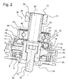
- FIG. 2 shows a side view of a second embodiment of a device according to the invention for phase shifting the rotational angle of a drive wheel to an output shaft in a sectional view, wherein the output shaft and the drive of the actuator are not shown.
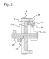
- FIG. 3 shows a schematic representation of an alternative embodiment of the device according to the invention for phase shifting the angle of rotation of a drive wheel to an output shaft.
- the devices according to the invention consist of a drive wheel 2, which has an outer toothing 4, in which, for example, a toothed belt engages, via which the drive wheel 2 is connected to a crankshaft for transmitting movement.
- the drive wheel 2 is rotatably connected to a drive gear 6 or made in one piece with this, the toothing 8 is formed on a front side on the circumference of the drive gear 6.
- the drive wheel 2 and the drive gear 6 are arranged rotatably about a common axis of rotation 10.
- the drive gear 6 meshes with a total of three transmission gears 12, the teeth 13 is formed on its outer circumference extending radially.
- the teeth 13 of the transmission gears 12 engage in a turn axially extending toothing 15 of a driven gear 14, which in turn is made in one piece with a driven gear 15.
- This driven gear 14 is rotatably mounted on a support member 16 which is secured via a secured against rotation screw 18 to an output shaft 20, which in FIG. 2 not shown in detail.
- the support member 16 has a substantially cylindrically shaped portion 19, at its first axial end a wall 22 extends in the radial direction, to which the driven gear 14 is fixed and its opposite second end abuts against the output shaft 20.
- the screw 18 is screwed from the first axial end of the support member 16 through a central bore 24 in a threaded hole 26 of the output shaft 20.
- the cylindrical portion 19 of the support member 16 is in the embodiment according to the FIG. 1 surrounded by a sleeve 28 which has a collar 30, which in turn abuts against an outer region of the output shaft 20.
- a sleeve 28 which has a collar 30, which in turn abuts against an outer region of the output shaft 20.
- a Drehachsenarme 32 is arranged, from which three bolts 33 extend in the radial direction at a distance of 120 ° distributed over the circumference, which serve as bearings for the transmission gears 12. These bolts are thus at right angles to the axis of rotation 10.
- the rotary axis support 32 is rotatably mounted on the sleeve 28 and in FIG. 2 arranged on the carrier element
- the transmission gears 12 are rotatable in both embodiments via an intermediate member 34 which is linearly movable via an actuator 36.
- the intermediate member 34 has a shoulder 38 against which an outer ring 40 of a ball bearing 42 axially abuts, which can be performed in a different form than sliding or rolling bearings.
- the outer ring 40 is fixed in its position relative to the intermediate member 34 via a securing ring 44, which is clamped in an inner circumferential groove 46 of the intermediate member 34.
- An inner ring 48 of the ball bearing 42 is disposed on an axially extending portion of an adjusting element 50 which has a shoulder 52 against which the inner ring 48 abuts axially and which is fixed on the opposite side via a second locking ring 53 on the adjusting element 50, in FIG. 2 is apparent.
- the adjusting element 50 has an internal thread 54 which cooperates with an external thread 56 of a worm 58, which is fastened on a drive shaft 60 of a drive unit, not shown, for example an electric motor.
- the adjusting element 50 is secured by a bolt 51 against rotation, so that by rotating the output shaft 60 and thus the worm 58 follows a linear movement of the adjusting element 50. This linear movement of the adjusting element 50 is transmitted via the ball bearing 42 to the intermediate member 34.
- the intermediate member 34 has three axial end portions 62 which each fully embrace a lever pin 64 which is fixed to a lever arm, not shown, which is fixedly connected to the respective transmission gear 12, so that the linear movement of the intermediate member 34 in a rotational movement of the respective transmission gear 12 converted becomes.
- the axial end portions 62 of the intermediate member 34 extend through corresponding openings of the carrier element 16.
- the movement of the drive wheel 4 via the transmission gears 12 and the output gear 14 is transmitted to the support member 16 and thus to the output shaft 20.
- the axial end portions 62 prevent the self-rotation of the transmission gears 12 by enclosing the lever pin 64, so that no relative movement between the drive gear 6 and the output gear 14 can occur.
- the entire gear 70 rotates with the intermediate member 34 and the output shaft 20 as a package with the speed of the drive wheel 4.
- the rotational movement of the transmission 70 and the output shaft 20 of the actuator 36 remains unchanged due to the ball bearing 42 in its position, although the Outer ring 40 of the ball bearing 42 is rotated, the inner ring 48, however, stops.
- An internal thread 72 of a fixed part 74 of the actuator 36 acts here with the external thread 56 of the screw 58 together, the rotationally fixed and axially displaceable on the drive shaft 60 of the not is shown attached drive unit.
- the screw 58 and thus the adjusting element 50 shifts in the axial direction on the drive shaft 60.
- the transmission of the movement remains according to the embodiment of FIG. 2 essentially identical to the one to FIG. 1 Described, wherein rotation of the transmission gears 12 relative to the drive gear 8 or the output gear 14 is prevented by an engagement of the intermediate member 34 to the transmission gears 12.
- the intermediate member 34 has for this purpose at its opposite to the ball bearing 42 axial end racks 78 which engage in the toothing 13 of the transmission gears 12.
- the transmission gears 12 are designed to be higher in this embodiment, so that they protrude radially beyond the outer circumference of the output gearwheel 14. In this outer region, the racks 78 can thus engage in the upper part of the transmission gears 12.
- the intermediate member 34 it is advantageous for the intermediate member 34 to choose a substantially hollow cylindrical shape, which is interrupted only by three axially extending slots, on whose one outer wall, the toothing of the racks 78 is formed. Accordingly, a rotation of the transmission gears 12 relative to the drive gear 8 or the output gear 14 is prevented by the self-locking of the worm gear, which prevents a linear displacement of the intermediate member 34, which would be required for a rotational rotation of the transmission gears 12.
- the intermediate member 34 is axially displaced by the axial movement of the screw 58 and the adjusting element 50, whereby the transmission gears 12 are rotated, so that the output gear 14 is rotated in the same way to the drive gear 8, as already in the Execution according to FIG. 1 has been described.
- FIG. 3 schematically illustrated embodiment differs from the embodiments according to the FIGS. 1 and 2 in that, instead of the axis of rotation carrier, the drive wheel 2 extends annularly in the axial direction on the outer circumference, wherein at the axial, pointing in the direction of the actuator 36 end radially inwardly facing bolts 33 are fixed or formed integrally with the drive wheel 2, on which the transmission gears 12th are stored.
- the transmission gears are in the manner already described with the integrally formed with the driven gear 15 driven gear 14 into engagement.
- the output gear 15 is arranged at least rotationally fixed on the output shaft 20.
- the transmission gears 12 in turn eccentrically arranged lever pin 64, which according to the invention via the actuator 36 and the linear displacement of the intermediate member 34 in the same manner as FIG. 1 has already been described, are set in rotation. Accordingly, in the FIG. 3 only the intermediate member 34 is shown.
- this embodiment is also to be changed insofar as that the transmission gears are mounted on the output gear and mesh with a drive gear.
- the described embodiments have a long service life, since the mechanical load of the actuator is minimized. In comparison to other known devices for phase adjustment, the energy requirement is significantly reduced, since a torque must be applied only during the adjustment.
Landscapes
- Engineering & Computer Science (AREA)
- Mechanical Engineering (AREA)
- General Engineering & Computer Science (AREA)
- Transmission Devices (AREA)
- Gear Transmission (AREA)
Applications Claiming Priority (1)
| Application Number | Priority Date | Filing Date | Title |
|---|---|---|---|
| DE200810060219 DE102008060219B4 (de) | 2008-12-04 | 2008-12-04 | Vorrichtung zur Phasenverschiebung des Drehwinkels eines Antriebsrades zu einer Abtriebswelle |
Publications (1)
| Publication Number | Publication Date |
|---|---|
| EP2194242A1 true EP2194242A1 (fr) | 2010-06-09 |
Family
ID=41395099
Family Applications (1)
| Application Number | Title | Priority Date | Filing Date |
|---|---|---|---|
| EP09176025A Withdrawn EP2194242A1 (fr) | 2008-12-04 | 2009-11-16 | Dispositif de décalage de phase de l'angle de rotation d'une roue motrice par rapport à un arbre mené |
Country Status (2)
| Country | Link |
|---|---|
| EP (1) | EP2194242A1 (fr) |
| DE (1) | DE102008060219B4 (fr) |
Families Citing this family (2)
| Publication number | Priority date | Publication date | Assignee | Title |
|---|---|---|---|---|
| DE102012102401B4 (de) | 2012-03-21 | 2016-01-07 | Kolbenschmidt Pierburg Innovations Gmbh | Vorrichtung zur Phasenverschiebung des Drehwinkels eines Antriebsrades zu einer Abtriebswelle |
| DE102012104921A1 (de) | 2012-06-06 | 2013-12-12 | Kolbenschmidt Pierburg Innovations Gmbh | Vorrichtung zur Phasenverschiebung des Drehwinkels eines Antriebsrades zu einer Abtriebswelle |
Citations (10)
| Publication number | Priority date | Publication date | Assignee | Title |
|---|---|---|---|---|
| DE3210914A1 (de) * | 1982-03-25 | 1983-09-29 | Atlas Fahrzeugtechnik GmbH, 5980 Werdohl | Nockenwellensteuergeraet |
| FR2526858A1 (fr) * | 1982-05-17 | 1983-11-18 | Alfa Romeo Auto Spa | Dispositif permettant de varier automatiquement le calage d'un arbre a cames |
| WO1988007125A1 (fr) * | 1987-03-17 | 1988-09-22 | Ford Motor Company Limited | Mecanisme de dephasage variable |
| GB2221513A (en) * | 1988-08-05 | 1990-02-07 | Ford Motor Co | Variable phase drive mechanism |
| DE4040486A1 (de) * | 1990-06-22 | 1992-01-02 | Schrick Gmbh Dr | Vorrichtung bei verbrennungsmotoren zur drehung der nockenwelle relativ zum nockenwellenantriebsrad |
| FR2665483A1 (fr) * | 1990-07-31 | 1992-02-07 | Atsugi Unisia Corp | Appareil de reglage de la commande des soupapes d'un moteur a combustion interne. |
| DE4311264A1 (de) * | 1993-04-06 | 1994-10-13 | Bosch Gmbh Robert | Vorrichtung zur Drehlagenänderung einer Gaswechselventile einer Brennkraftmaschine steuernden Steuerwelle |
| US5680836A (en) | 1996-09-17 | 1997-10-28 | General Motors Corporation | Planetary cam phaser with lash compensation |
| US6457446B1 (en) * | 1999-09-22 | 2002-10-01 | Aimbridge Pty Ltd. | Phase control mechanism |
| EP0903470B1 (fr) | 1997-09-19 | 2003-09-10 | TCG UNITECH Aktiengesellschaft | Dispositif pour varier le calage d'un arbre à cames de moteur à combustion interne |
Family Cites Families (3)
| Publication number | Priority date | Publication date | Assignee | Title |
|---|---|---|---|---|
| DE3631733A1 (de) * | 1986-09-18 | 1988-03-24 | Kloeckner Humboldt Deutz Ag | Vorrichtung an einer brennkraftmaschine zur aenderung des foerderbeginns und/oder der ventilsteuerzeiten |
| DE3737602A1 (de) * | 1987-11-05 | 1989-05-18 | Interatom | Einrichtung zum veraendern der steuerzeiten der ventile einer verbrennungskraftmaschine mittels eines differentialgetriebes |
| US7475661B2 (en) * | 2006-10-17 | 2009-01-13 | Delphi Technologies, Inc. | Camshaft phaser having a differential bevel gear system |
-
2008
- 2008-12-04 DE DE200810060219 patent/DE102008060219B4/de not_active Expired - Fee Related
-
2009
- 2009-11-16 EP EP09176025A patent/EP2194242A1/fr not_active Withdrawn
Patent Citations (10)
| Publication number | Priority date | Publication date | Assignee | Title |
|---|---|---|---|---|
| DE3210914A1 (de) * | 1982-03-25 | 1983-09-29 | Atlas Fahrzeugtechnik GmbH, 5980 Werdohl | Nockenwellensteuergeraet |
| FR2526858A1 (fr) * | 1982-05-17 | 1983-11-18 | Alfa Romeo Auto Spa | Dispositif permettant de varier automatiquement le calage d'un arbre a cames |
| WO1988007125A1 (fr) * | 1987-03-17 | 1988-09-22 | Ford Motor Company Limited | Mecanisme de dephasage variable |
| GB2221513A (en) * | 1988-08-05 | 1990-02-07 | Ford Motor Co | Variable phase drive mechanism |
| DE4040486A1 (de) * | 1990-06-22 | 1992-01-02 | Schrick Gmbh Dr | Vorrichtung bei verbrennungsmotoren zur drehung der nockenwelle relativ zum nockenwellenantriebsrad |
| FR2665483A1 (fr) * | 1990-07-31 | 1992-02-07 | Atsugi Unisia Corp | Appareil de reglage de la commande des soupapes d'un moteur a combustion interne. |
| DE4311264A1 (de) * | 1993-04-06 | 1994-10-13 | Bosch Gmbh Robert | Vorrichtung zur Drehlagenänderung einer Gaswechselventile einer Brennkraftmaschine steuernden Steuerwelle |
| US5680836A (en) | 1996-09-17 | 1997-10-28 | General Motors Corporation | Planetary cam phaser with lash compensation |
| EP0903470B1 (fr) | 1997-09-19 | 2003-09-10 | TCG UNITECH Aktiengesellschaft | Dispositif pour varier le calage d'un arbre à cames de moteur à combustion interne |
| US6457446B1 (en) * | 1999-09-22 | 2002-10-01 | Aimbridge Pty Ltd. | Phase control mechanism |
Also Published As
| Publication number | Publication date |
|---|---|
| DE102008060219B4 (de) | 2011-07-14 |
| DE102008060219A1 (de) | 2010-06-17 |
Similar Documents
| Publication | Publication Date | Title |
|---|---|---|
| EP0254058B1 (fr) | Arbre à cames pour le réglage des soupapes d'admission et d'échappement d'un moteur à combustion interne | |
| DE102008021220B4 (de) | Vorrichtung zur Phasenverschiebung des Drehwinkels eines Antriebsrades zu einer Abtriebswelle | |
| DE102009013996A1 (de) | Einrichtung zur Verstellung der Exzentrizität für ein Kurbel-CVT-Getriebe | |
| WO2008052531A1 (fr) | Entraînement de réglage pour le réglage local d'un composant de suspension | |
| EP2850292B1 (fr) | Unité d'arbres à cames | |
| EP2616644B1 (fr) | Dispositif de déphasage de l'angle de rotation d'un pignon d'entrée par rapport à un pignon de sortie | |
| DE102008039009A1 (de) | Nockenwellenversteller | |
| DE10315151A1 (de) | Vorrichtung zur relativen Winkelverstellung einer Nockenwelle gegenüber dem antreibenden Antriebsrad | |
| DE102015102543B3 (de) | Vorrichtung zur Phasenverschiebung des Drehwinkels eines Antriebsteils zu einem Abtriebsteil | |
| DE102008060219B4 (de) | Vorrichtung zur Phasenverschiebung des Drehwinkels eines Antriebsrades zu einer Abtriebswelle | |
| DE102006042511B4 (de) | Kompakte Verriegelungsvorrichtung | |
| DE102013015844A1 (de) | Übertragungsvorrichtung mit exzentrischer Triebstockkomponente | |
| DE19549331C2 (de) | Stelleinrichtung für ein Koppelgetriebe | |
| DE102012102401B4 (de) | Vorrichtung zur Phasenverschiebung des Drehwinkels eines Antriebsrades zu einer Abtriebswelle | |
| CH660055A5 (de) | Einrichtung zur aenderung der ventil- und/oder einspritzsteuerzeiten an einer hubkolbenbrennkraftmaschine. | |
| EP0732483A2 (fr) | Transmission par engrenage | |
| DE102010033897B4 (de) | Nockenwellen-Verstellvorrichtung | |
| DE19504132C2 (de) | Stelleinrichtung für ein Koppelgetriebe | |
| DE4417959A1 (de) | Vorrichtung zum Verändern der Steuerzeiten einer Brennkraftmaschine | |
| DE102011001612B4 (de) | Vorrichtung zur diskreten Phasenverschiebung | |
| EP2859197A1 (fr) | Dispositif destiné à déphaser l'angle de rotation d'une roue d'entraînement par rapport à un arbre de sortie | |
| DE102011076944A1 (de) | Wolfromexzentergetriebe und Vorrichtung mit einem Wolfromexzentergetriebe | |
| EP2086816B1 (fr) | Dispositif de superposition de vitesses dote d'un entrainement auxiliaire | |
| WO2013023924A1 (fr) | Arbre à cames, en particulier pour moteurs de véhicules à moteur | |
| WO2016062433A1 (fr) | Dispositif de déphasage de l'angle de rotation d'un élément d'entraînement par rapport à un élément de sortie |
Legal Events
| Date | Code | Title | Description |
|---|---|---|---|
| PUAI | Public reference made under article 153(3) epc to a published international application that has entered the european phase |
Free format text: ORIGINAL CODE: 0009012 |
|
| AK | Designated contracting states |
Kind code of ref document: A1 Designated state(s): AT BE BG CH CY CZ DE DK EE ES FI FR GB GR HR HU IE IS IT LI LT LU LV MC MK MT NL NO PL PT RO SE SI SK SM TR |
|
| AX | Request for extension of the european patent |
Extension state: AL BA RS |
|
| 17P | Request for examination filed |
Effective date: 20101006 |
|
| STAA | Information on the status of an ep patent application or granted ep patent |
Free format text: STATUS: THE APPLICATION IS DEEMED TO BE WITHDRAWN |
|
| 18D | Application deemed to be withdrawn |
Effective date: 20101210 |