EP2194254A2 - Steuergehäuse, entweder für eine Kette oder einen Riemen sowie Zylinderblock für einen Verbrennungsmotor - Google Patents
Steuergehäuse, entweder für eine Kette oder einen Riemen sowie Zylinderblock für einen Verbrennungsmotor Download PDFInfo
- Publication number
- EP2194254A2 EP2194254A2 EP09177152A EP09177152A EP2194254A2 EP 2194254 A2 EP2194254 A2 EP 2194254A2 EP 09177152 A EP09177152 A EP 09177152A EP 09177152 A EP09177152 A EP 09177152A EP 2194254 A2 EP2194254 A2 EP 2194254A2
- Authority
- EP
- European Patent Office
- Prior art keywords
- opening
- chain
- belt
- crankcase
- distribution
- Prior art date
- Legal status (The legal status is an assumption and is not a legal conclusion. Google has not performed a legal analysis and makes no representation as to the accuracy of the status listed.)
- Ceased
Links
Images


Classifications
-
- F—MECHANICAL ENGINEERING; LIGHTING; HEATING; WEAPONS; BLASTING
- F02—COMBUSTION ENGINES; HOT-GAS OR COMBUSTION-PRODUCT ENGINE PLANTS
- F02F—CYLINDERS, PISTONS OR CASINGS, FOR COMBUSTION ENGINES; ARRANGEMENTS OF SEALINGS IN COMBUSTION ENGINES
- F02F7/00—Casings, e.g. crankcases
- F02F7/0065—Shape of casings for other machine parts and purposes, e.g. utilisation purposes, safety
- F02F7/0073—Adaptations for fitting the engine, e.g. front-plates or bell-housings
-
- F—MECHANICAL ENGINEERING; LIGHTING; HEATING; WEAPONS; BLASTING
- F02—COMBUSTION ENGINES; HOT-GAS OR COMBUSTION-PRODUCT ENGINE PLANTS
- F02B—INTERNAL-COMBUSTION PISTON ENGINES; COMBUSTION ENGINES IN GENERAL
- F02B67/00—Engines characterised by the arrangement of auxiliary apparatus not being otherwise provided for, e.g. the apparatus having different functions; Driving auxiliary apparatus from engines, not otherwise provided for
- F02B67/04—Engines characterised by the arrangement of auxiliary apparatus not being otherwise provided for, e.g. the apparatus having different functions; Driving auxiliary apparatus from engines, not otherwise provided for of mechanically-driven auxiliary apparatus
- F02B67/06—Engines characterised by the arrangement of auxiliary apparatus not being otherwise provided for, e.g. the apparatus having different functions; Driving auxiliary apparatus from engines, not otherwise provided for of mechanically-driven auxiliary apparatus driven by means of chains, belts, or like endless members
-
- F—MECHANICAL ENGINEERING; LIGHTING; HEATING; WEAPONS; BLASTING
- F02—COMBUSTION ENGINES; HOT-GAS OR COMBUSTION-PRODUCT ENGINE PLANTS
- F02B—INTERNAL-COMBUSTION PISTON ENGINES; COMBUSTION ENGINES IN GENERAL
- F02B2275/00—Other engines, components or details, not provided for in other groups of this subclass
- F02B2275/06—Endless member is a belt
-
- F—MECHANICAL ENGINEERING; LIGHTING; HEATING; WEAPONS; BLASTING
- F02—COMBUSTION ENGINES; HOT-GAS OR COMBUSTION-PRODUCT ENGINE PLANTS
- F02B—INTERNAL-COMBUSTION PISTON ENGINES; COMBUSTION ENGINES IN GENERAL
- F02B2275/00—Other engines, components or details, not provided for in other groups of this subclass
- F02B2275/08—Endless member is a chain
Definitions
- the present invention relates, in general, to a timing casing indifferently housing a chain or a belt and a cylinder block for an internal combustion engine.
- a distribution casing is, in general, fixed on the front side of the cylinder block of the engine and comprises at least one crankcase receiving at least partially a first coupling means of the crankshaft and a cylinder head receiving second coupling means with camshafts.
- This distribution casing comprises transmission means for transmitting the movement of the first coupling means via second coupling means with respectively the respective opening and closing means of at least one inlet and outlet valve. at least one exhaust valve.
- the second coupling means and a portion of the transmission means are preferably housed in a cylinder block, located above the crankcase.
- valves said intake and exhaust, arranged in the cylinder head, engine part covering the cylinder block.
- One or more means for opening and closing the intake and exhaust valves for example camshafts, cause, in a synchronized manner, the opening and closing of these valves.
- This or these camshafts are arranged in the cylinder head and are rotated by the crankshaft using the coupling means with the appropriate drive ratio, located at its end. All drive elements are housed in the timing case, either in a crankcase or in a cylinder head box.
- the figure 1 shows the known principle of a belt drive mechanism 1.
- the material retained for it is preferably the rubber with an inner cable.
- the system consists of a belt 1 coupling a timing gear 2, as the first coupling means, integral with the crankshaft with a drive sprocket 3 of the camshaft for the intake valves and a drive gear 4 of the camshaft for the exhaust valves. These two drive gears 3 and 4 form the second coupling means.
- the windings at the different elements to be driven and the tension of the belt are provided by at least one winding roller 5 and a tensioning roller 6.
- crankcase 7 As shown in figure 2 This technology does not require any lubrication and does not require the use of a perfectly sealed C distribution cover.
- the various elements of the system are generally protected from external projections by a crankcase in the form of a crankcase 7 surmounted by a cylinder head chamber 8.
- These two boxes 7 and 8 are each provided with a respective lid 7a and 8a , mostly plastic.
- the figure 3 shows the known principle of a chain drive mechanism 1 a.
- the material retained for it is steel.
- strings such as socket chains or roller chains.
- the system consists of a chain 1a coupling a timing gear 2a integral with the crankshaft with a drive gear 3a of the camshaft for the intake valves and a drive gear 4a of the camshaft for the exhaust valves.
- a chain 1a For the coupling technology comprising a chain 1a, the windings at the different elements to be driven and the tension of the chain 1a are provided by at least one winding pad 9 and a tensioning pad 10, itself actuated by a hydraulic tensioner 11
- Another winding pad 12 guards the chain 1a located between the two pinions 3a and 4a.
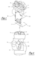
- the figure 4 shows an example of boxes for a distribution casing C 'with chain.
- This distribution casing C ' is located at the front end of the cylinder block C1 of the engine, intended to be surmounted by a cylinder head.
- the distribution casing C ' consists of a cylinder head chamber 14 comprising the upper part of the chain system including the drive gears 3a and 4a intake and exhaust camshafts and substantially extending the front end of the breech.
- the timing case C ' comprises a crankcase 13 comprising the lower and middle portion of the chain system and substantially extending the front end of the cylinder block C1.
- the problem underlying the present invention is to design an identical distribution casing which can receive both types of existing drive, that is to say, either a chain distribution or a belt distribution, that in leaving the motor base unchanged.
- the subject of the invention is a distribution casing for a combustion engine, receiving a mechanism for driving the opening and closing of the valves of said engine, said mechanism comprising means for transmitting the rotation of the crankshaft to a or more camshafts, this distribution casing having at least one opening for mounting said mechanism in its interior, said opening being sealed by a closing means once said mounted mechanism, characterized in that its dimensions and shapes as well as those of its opening are determined to take into account the specific characteristics of the transmission means with chain or belt to receive indifferently one or the other.
- the distribution casing consists of a crankcase with a front opening for receiving the first part of said mechanism comprising a first means of coupling with the crankshaft, the transmission means of the chain or belt type being integral with this first coupling means, this crankcase being surmounted by a cylinder head chamber provided with an upper opening and receiving the second part of said mechanism comprising second coupling means with the transmission means, each second coupling means being respectively connected to the system for opening and closing at least one intake valve and at least one exhaust valve, arranged at the upper part of this distribution case.
- crankcase and the cylinder head are monobloc.
- the opening of the crankcase is made in the form of a hatch closed by a cover plate.
- the hatch of the crankcase has dimensions determined by extending above this passage to allow the coupling of this shaft with the crankshaft via a drive pinion, the cover plate also covering this passage.
- the seal between the hatch and the cover plate is essentially flat and vertical.
- the upper opening of the cylinder head chamber is closed by a cylinder head cover, this opening being substantially in a horizontal plane.
- these further comprise a tensioning roller and a roller, as well as their fastening means on the distribution casing.
- these comprise, in addition, a tensioning pad, a winding pad, a hydraulic tensioner actuating the tensioner pad, as well as their fastening means on the timing cover.
- the second coupling means when the first coupling means is a crankshaft timing gear while the second coupling means are two camshaft drive sprockets for the intake and the exhaust, the second coupling means further comprising, in the case of a chain drive, a chain guide overlying the intermediate surface between the two drive gears to provide guidance for the chain portion between these two gears.
- the invention is particularly applicable to a motor unit, especially for a motor vehicle, comprising a cylinder block bearing on one of its faces a distribution housing as described above, suitable for a drive chain or belt.
- the Figures 5 and 6 take up the main features of a training mechanism shown in the figure 1 in a timing case according to the present invention.
- This timing cover receives Figures 5 and 6 a belt 1, dry or wet, with its drive mechanism but the dimensions of the housing and its shape are not changed.
- This crankcase consists of a crankcase C3 surmounted by a C2 cylinder box.
- the two boxes C2 and C3 are advantageously monobloc and are also with the cylinder block C1 which carries them on its front face, as it will be better seen at the figure 7 .
- the crankcase C3 has a front opening which is sealed by a cover plate 15 with fastening means 16 distributed on its periphery and advantageously by inserting a seal between the plate 15 and the body of the crankcase C3.
- the opening is in the form of a hatch, that is to say that it does not extend over the entire upper surface of the crankcase C3.
- the cover plate 15 is advantageously flat and vertical in the working position.
- This opening is left free to the figure 6 to show the positioning of the various elements of the belt drive mechanism 1, including the rollers 5 and 6 and the crankshaft pinion 2. These are mounted through the opening of the crankcase C3, formed on the front face.
- the cylinder block chamber C2 also has an opening which is located at its upper part and which will be covered, in a sealed manner, by the cylinder head cover, not shown in these figures.
- the plane of this opening is substantially horizontal and the cylinder head chamber C2 does not fully encompass the pinions 3 and 4 for driving a camshaft, stopping substantially lower than the mid-height of these.
- These pinions 3 and 4 are mounted in the cylinder head box C2 from the top of this box through the upper opening, and their respective central axis remains accessible from the front face of the timing case.
- the distribution casing is arranged in such a way as to indifferently receive a belt drive mechanism 1 or chain. This has been made possible because its dimensions and shapes as well as those of its openings, in particular that of the crankcase C3, are determined to take into account the specific characteristics of the transmission means with chain or belt in order to indifferently receive the one or the other.
- crankcase opening C3 corresponding to the opening required to allow access to the elements of the two embodiments as well as access to their attachment means, these elements not distributed in the box in the same way for a chain or belt.
- crankcase C3 It may be advantageous to choose a limited opening of the crankcase C3, ie the minimum opening that allows the assembly of the elements of the two technologies to be positioned in the crankcase C3. This ensures a better seal between the box C3 and the cover plate 15.
- the opening may not be above the seal at the end of the crankshaft so as not to cause a so-called T seal which is usually a source of oil leaks.
- the figure 7 shows a cylinder block C1, according to the present invention, comprising on its front face such a distribution case indifferently for chain or belt.
- the cylinder block is integral with the timing case.
- this cylinder block C1 further comprises a balancing shaft, which represents another embodiment of the invention indifferently for a belt or for a chain.
- the shaft or one of the balance shafts is rotated by a gear system having a pinion integral with the crankshaft, if necessary the other balancer shaft being driven by the first also by a gear means.
- the cover plate 17 is modified so that a portion 17a thereof covers the passage of the balancing shaft, to achieve a seal for it. This can be valid for both types of drive either by chain or belt.
- FIGS. Figures 5 and 6 are to be reconciled respectively with Figures 5 and 6 to compare the housing of a chain drive mechanism as shown in figures 8 and 9 with the housing of a belt mechanism in a timing case according to the present invention, as shown in FIGS. Figures 5 and 6 .
- timing case in particular the crankcase C3 and the cylinder head box C2 are the same and the dimensions and shapes of the respective opening of these boxes C2 and C3.
- the heights of the cylinder head box C2 and the cylinder head cover were determined to be able to receive the chain guide 12, arranged above the part of the chain 1a located between the two pinions 3a and 4a. , and whose equivalent does not exist in the belt drive.
- the shape of the opening of the crankcase C3 allows access to the winding pad 9 of the chain 1a and the tensioning pad 10 thereof and to the hydraulic tensioner 11 of the tensioner pad 10 and the crankshaft pinion 2a.
- This opening also allows access to their attachment means in the crankcase C3 to facilitate their implementation.
- this opening of the crankcase is closed by the same cover plate 15 as in the belt drive embodiment.
- the main advantage of the present invention makes it possible to develop a distribution casing. This also allows, when it is monoblock with the cylinder block, to develop only one motor base for two types of technologically different distribution drive, so that one or / and the other can be at proposed term on the different engines of a family.
- An auxiliary advantage of the present invention compared to a chain distribution casing of the state of the art, is to reinforce the tightness of the distribution casing, in particular of the crankcase by the use of a substantially flat cover plate over an opening made in this box, which has been determined to be minimal while allowing access to all the elements contained in this box and to have a favorable shape to strengthen the tightness of this box.
- Another auxiliary advantage of the present invention is to also guarantee a good sealing of the distribution casing and in particular of the crankcase in the case of an embodiment of the cylinder block using a balancing shaft, the cover plate of the casing performing also the cover of the passage of this tree.
Landscapes
- Engineering & Computer Science (AREA)
- Chemical & Material Sciences (AREA)
- Combustion & Propulsion (AREA)
- Mechanical Engineering (AREA)
- General Engineering & Computer Science (AREA)
- Cylinder Crankcases Of Internal Combustion Engines (AREA)
- Valve-Gear Or Valve Arrangements (AREA)
- Valve Device For Special Equipments (AREA)
- Devices For Conveying Motion By Means Of Endless Flexible Members (AREA)
Applications Claiming Priority (1)
| Application Number | Priority Date | Filing Date | Title |
|---|---|---|---|
| FR0858217A FR2939179B1 (fr) | 2008-12-03 | 2008-12-03 | Carter de distribution logeant indiferrement une chaine ou une courroie ainsi que bloc cylindres pour un moteur a combustion interne. |
Publications (2)
| Publication Number | Publication Date |
|---|---|
| EP2194254A2 true EP2194254A2 (de) | 2010-06-09 |
| EP2194254A3 EP2194254A3 (de) | 2015-04-15 |
Family
ID=40857825
Family Applications (1)
| Application Number | Title | Priority Date | Filing Date |
|---|---|---|---|
| EP09177152.7A Ceased EP2194254A3 (de) | 2008-12-03 | 2009-11-26 | Steuergehäuse, entweder für eine Kette oder einen Riemen sowie Zylinderblock für einen Verbrennungsmotor |
Country Status (2)
| Country | Link |
|---|---|
| EP (1) | EP2194254A3 (de) |
| FR (1) | FR2939179B1 (de) |
Cited By (1)
| Publication number | Priority date | Publication date | Assignee | Title |
|---|---|---|---|---|
| FR3135304A1 (fr) * | 2022-05-05 | 2023-11-10 | Psa Automobiles Sa | Groupe moteur comportant un support combine de fixation de composant, vehicule automobile comportant un tel groupe moteur |
Families Citing this family (1)
| Publication number | Priority date | Publication date | Assignee | Title |
|---|---|---|---|---|
| FR3012531B1 (fr) * | 2013-10-31 | 2015-12-04 | Peugeot Citroen Automobiles Sa | Carter-cylindres d'un moteur a combustion interne. |
Family Cites Families (7)
| Publication number | Priority date | Publication date | Assignee | Title |
|---|---|---|---|---|
| JPH031240U (de) * | 1989-05-30 | 1991-01-09 | ||
| JP2570992Y2 (ja) * | 1991-03-18 | 1998-05-13 | 三菱自動車工業株式会社 | エンジン構造 |
| DE19511864C1 (de) * | 1995-03-31 | 1996-07-25 | Daimler Benz Ag | Brennkraftmaschine |
| JP3840037B2 (ja) * | 2000-05-23 | 2006-11-01 | 富士重工業株式会社 | エンジンのブリーザ装置 |
| JP2005344699A (ja) * | 2004-06-01 | 2005-12-15 | Shinichiro Yamamoto | 別体式タイミングケース(カムチェーンとテンショナー一体型別体式タイミングケース、またはタイミングベルトとテンショナー一体型別体式タイミングケース、またはカムギア内臓別体式タイミングケース) |
| JP2006070758A (ja) * | 2004-08-31 | 2006-03-16 | Aichi Mach Ind Co Ltd | 内燃機関 |
| DE102004050440A1 (de) * | 2004-10-16 | 2006-05-04 | Audi Ag | Zylinderkurbelgehäuse für eine Hubkolben-Brennkraftmaschine |
-
2008
- 2008-12-03 FR FR0858217A patent/FR2939179B1/fr active Active
-
2009
- 2009-11-26 EP EP09177152.7A patent/EP2194254A3/de not_active Ceased
Non-Patent Citations (1)
| Title |
|---|
| None * |
Cited By (1)
| Publication number | Priority date | Publication date | Assignee | Title |
|---|---|---|---|---|
| FR3135304A1 (fr) * | 2022-05-05 | 2023-11-10 | Psa Automobiles Sa | Groupe moteur comportant un support combine de fixation de composant, vehicule automobile comportant un tel groupe moteur |
Also Published As
| Publication number | Publication date |
|---|---|
| FR2939179A1 (fr) | 2010-06-04 |
| FR2939179B1 (fr) | 2013-04-12 |
| EP2194254A3 (de) | 2015-04-15 |
Similar Documents
| Publication | Publication Date | Title |
|---|---|---|
| FR2481743A1 (fr) | Reniflard pour moteurs a soupapes en tete | |
| FR2773589A1 (fr) | Moteur thermique pour un instrument de travail portatif guide manuellement | |
| FR2611808A1 (fr) | Moteur de vehicule comprenant un orifice de demontage du vilebrequin | |
| FR3084108A1 (fr) | Structure de couvercle d’un moteur a combustion interne | |
| WO2007085740A1 (fr) | Ensemble culasse et bloc moteur pour moteur a rapport volumetrique variable | |
| FR2575693A1 (fr) | Dispositif d'admission d'air pour moteur, et scie a chaine | |
| JP4197067B2 (ja) | 車両用エンジンの動力伝達装置 | |
| FR3084107A1 (fr) | Structure de couvercle d'un moteur a combustion interne | |
| EP2194254A2 (de) | Steuergehäuse, entweder für eine Kette oder einen Riemen sowie Zylinderblock für einen Verbrennungsmotor | |
| EP0560701A1 (de) | Verbrennungskraftmaschine mit einem veränderlichen Verdichtungsverhältnis und einer regelbaren drehenden Masse des Schwungrades | |
| EP0124433A2 (de) | Abnehmbares Gehäuse für den Nockenwellenantrieb einer Brennkraftmaschine | |
| JP5315066B2 (ja) | 内燃機関用ウォータポンプにおけるシール構造 | |
| FR2846712A1 (fr) | Moteur a usage general | |
| TWI244525B (en) | Exhaust gas sensor mounting structure for cylinder head of an internal combustion engine | |
| FR2643417A1 (fr) | Ensemble de soupape pour moteurs a explosion | |
| KR100688221B1 (ko) | 내연기관의 보조 기구 부착 구조 | |
| FR3066539A1 (fr) | Structure de traitement de gaz de carter dans un systeme de recuperation de gaz de carter moteur pour moteur a combustion interne | |
| FR3145188A1 (fr) | Ensemble pour moteur a combustion interne (m) | |
| FR2879650A1 (fr) | Agencement de pompe a huile | |
| EP1653072B1 (de) | Schutzverkleidung einer Brennfraftmaschine | |
| FR2877702A1 (fr) | Vis entraineur joint de oldham pour pompe a vide | |
| FR3069576A1 (fr) | Moteur avec un arbre d'entrainement integre et une trappe d'acces a cet arbre | |
| EP1541848A1 (de) | Motor für motorroller | |
| FR3001763A1 (fr) | Pompe a huile de vehicule automobile a emulsion reduite | |
| JP4259656B2 (ja) | 車両用エンジン |
Legal Events
| Date | Code | Title | Description |
|---|---|---|---|
| PUAI | Public reference made under article 153(3) epc to a published international application that has entered the european phase |
Free format text: ORIGINAL CODE: 0009012 |
|
| AK | Designated contracting states |
Kind code of ref document: A2 Designated state(s): AT BE BG CH CY CZ DE DK EE ES FI FR GB GR HR HU IE IS IT LI LT LU LV MC MK MT NL NO PL PT RO SE SI SK SM TR |
|
| RAP1 | Party data changed (applicant data changed or rights of an application transferred) |
Owner name: PEUGEOT CITROEN AUTOMOBILES SA Owner name: GM GLOBAL TECHNOLOGY OPERATIONS LLC |
|
| PUAL | Search report despatched |
Free format text: ORIGINAL CODE: 0009013 |
|
| AK | Designated contracting states |
Kind code of ref document: A3 Designated state(s): AT BE BG CH CY CZ DE DK EE ES FI FR GB GR HR HU IE IS IT LI LT LU LV MC MK MT NL NO PL PT RO SE SI SK SM TR |
|
| RIC1 | Information provided on ipc code assigned before grant |
Ipc: F02B 67/06 20060101AFI20150311BHEP Ipc: F02F 7/00 20060101ALI20150311BHEP |
|
| 17P | Request for examination filed |
Effective date: 20150819 |
|
| RBV | Designated contracting states (corrected) |
Designated state(s): AT BE BG CH CY CZ DE DK EE ES FI FR GB GR HR HU IE IS IT LI LT LU LV MC MK MT NL NO PL PT RO SE SI SK SM TR |
|
| RAP1 | Party data changed (applicant data changed or rights of an application transferred) |
Owner name: PSA AUTOMOBILES SA Owner name: GM GLOBAL TECHNOLOGY OPERATIONS LLC |
|
| 17Q | First examination report despatched |
Effective date: 20180215 |
|
| 18R | Application refused |
Effective date: 20180629 |