EP2194273A1 - Verstellbarer verdichter - Google Patents
Verstellbarer verdichter Download PDFInfo
- Publication number
- EP2194273A1 EP2194273A1 EP08835453A EP08835453A EP2194273A1 EP 2194273 A1 EP2194273 A1 EP 2194273A1 EP 08835453 A EP08835453 A EP 08835453A EP 08835453 A EP08835453 A EP 08835453A EP 2194273 A1 EP2194273 A1 EP 2194273A1
- Authority
- EP
- European Patent Office
- Prior art keywords
- valve
- pressure
- valve element
- acting
- solenoid
- Prior art date
- Legal status (The legal status is an assumption and is not a legal conclusion. Google has not performed a legal analysis and makes no representation as to the accuracy of the status listed.)
- Granted
Links
Images


Classifications
-
- F—MECHANICAL ENGINEERING; LIGHTING; HEATING; WEAPONS; BLASTING
- F04—POSITIVE - DISPLACEMENT MACHINES FOR LIQUIDS; PUMPS FOR LIQUIDS OR ELASTIC FLUIDS
- F04B—POSITIVE-DISPLACEMENT MACHINES FOR LIQUIDS; PUMPS
- F04B27/00—Multi-cylinder pumps specially adapted for elastic fluids and characterised by number or arrangement of cylinders
- F04B27/08—Multi-cylinder pumps specially adapted for elastic fluids and characterised by number or arrangement of cylinders having cylinders coaxial with, or parallel or inclined to, main shaft axis
- F04B27/14—Control
- F04B27/16—Control of pumps with stationary cylinders
- F04B27/18—Control of pumps with stationary cylinders by varying the relative positions of a swash plate and a cylinder block
- F04B27/1804—Controlled by crankcase pressure
- F04B2027/1822—Valve-controlled fluid connection
- F04B2027/1827—Valve-controlled fluid connection between crankcase and discharge chamber
-
- F—MECHANICAL ENGINEERING; LIGHTING; HEATING; WEAPONS; BLASTING
- F04—POSITIVE - DISPLACEMENT MACHINES FOR LIQUIDS; PUMPS FOR LIQUIDS OR ELASTIC FLUIDS
- F04B—POSITIVE-DISPLACEMENT MACHINES FOR LIQUIDS; PUMPS
- F04B27/00—Multi-cylinder pumps specially adapted for elastic fluids and characterised by number or arrangement of cylinders
- F04B27/08—Multi-cylinder pumps specially adapted for elastic fluids and characterised by number or arrangement of cylinders having cylinders coaxial with, or parallel or inclined to, main shaft axis
- F04B27/14—Control
- F04B27/16—Control of pumps with stationary cylinders
- F04B27/18—Control of pumps with stationary cylinders by varying the relative positions of a swash plate and a cylinder block
- F04B27/1804—Controlled by crankcase pressure
- F04B2027/1822—Valve-controlled fluid connection
- F04B2027/1831—Valve-controlled fluid connection between crankcase and suction chamber
-
- F—MECHANICAL ENGINEERING; LIGHTING; HEATING; WEAPONS; BLASTING
- F04—POSITIVE - DISPLACEMENT MACHINES FOR LIQUIDS; PUMPS FOR LIQUIDS OR ELASTIC FLUIDS
- F04B—POSITIVE-DISPLACEMENT MACHINES FOR LIQUIDS; PUMPS
- F04B27/00—Multi-cylinder pumps specially adapted for elastic fluids and characterised by number or arrangement of cylinders
- F04B27/08—Multi-cylinder pumps specially adapted for elastic fluids and characterised by number or arrangement of cylinders having cylinders coaxial with, or parallel or inclined to, main shaft axis
- F04B27/14—Control
- F04B27/16—Control of pumps with stationary cylinders
- F04B27/18—Control of pumps with stationary cylinders by varying the relative positions of a swash plate and a cylinder block
- F04B27/1804—Controlled by crankcase pressure
- F04B2027/184—Valve controlling parameter
- F04B2027/1859—Suction pressure
Definitions
- This invention relates to a variable displacement compressor used in an automotive air conditioning system.
- a variable displacement reciprocating compressor used in an automotive air conditioning system has a housing, and inside the housing, a discharge chamber, a suction chamber, a crank chamber and cylinder bores are defined.
- a swashplate is mounted to be variable in inclination, and a conversion mechanism including the swashplate converts rotation of the drive shaft into reciprocating motion of pistons fitted within the respective cylinder bores.
- each piston performs a discharge process of drawing a working fluid from the suction chamber into its own cylinder bore, compressing the drawn-in working fluid and discharging the compressed working fluid to the discharge chamber.
- a displacement control valve is arranged in a gas supply passage connecting the discharge chamber and the crank chamber, and a restriction is provided between the crank chamber and the suction chamber.
- Equation (1) can be rearranged into equation (2) giving an acting pressure difference ⁇ P (difference between discharge pressure Pd and suction pressure Ps).
- Sv is the area of that surface of the valve element which receives the discharge pressure
- Pd is the discharge pressure
- Ps is the suction pressure
- f1 is a force exerted by a compression coil spring 28
- f2 is a force exerted by a compression coil spring 27
- F(I) is an electromagnetic force generated by a solenoid supplied with a control current I. It is arranged that f1 and f2 satisfy a relationship f1>f2.
- Equation (3) shows the graph of equation (3).
- FIG. 6 shows that the acting pressure difference ⁇ P, namely Pd-Ps is in proportion to control current, and that a maximum acting pressure difference ⁇ Pmax requires a maximum value Imax of control current.
- the acting pressure difference ⁇ P thus varies from 0 to ⁇ Pmax as the control current is regulated in the range of 0 to Imax.
- Imin being not 0 leads to a great gradient of the acting pressure difference ⁇ P varying depending on the current, which means a slight variation in control current I results in a significant variation in Pd-Ps.
- the great gradient of the acting pressure difference varying depending on the current means that the coefficient A/Sv of the current I in equation (3) needs to be great in order to achieve the maximum acting pressure difference ⁇ Pmax.
- Sv is the area of the surface which receives the discharge pressure, and at the same time the area of the surface which receives the suction pressure. Smaller area Sv results in lower sensitivity of the valve element responding to variations in discharge pressure or suction pressure, which may impair the stability of displacement control.
- An object of the present invention is to provide a variable displacement compressor provided with a displacement control valve designed to make effective use of an electromagnetic force generated by a solenoid and superior in control stability.
- a variable displacement compressor comprising a housing with a discharge pressure section, a suction pressure section, a crank chamber and cylinder bores defined inside, pistons fitted in the respective cylinder bores, a drive shaft rotatably supported inside the housing, a conversion mechanism including a swashplate variable in inclination and converting rotation of the drive shaft into reciprocating motion of the pistons, a displacement control valve opening and closing a first connection passage connecting the discharge pressure section and the crank chamber, and a restriction provided in a second connection passage connecting the crank chamber and the suction pressure section, where the stroke of the pistons is regulated by regulating the extent to which the displacement control valve is opened, thereby varying pressure in the crank chamber, wherein the displacement control valve includes a valve element having a discharge pressure receiving surface which receives pressure in the discharge pressure section and a suction pressure receiving surface which receives pressure in the suction pressure section acting in a direction opposite to the direction that the pressure in the discharge pressure section acts
- variable displacement compressor when the solenoid of the displacement control valve ceases to be excited, so that the electromagnetic force generated by the solenoid becomes zero, the valve element is brought into the valve closing position. This means that the displacement is controlled by making effective use of the electromagnetic force generated by the solenoid from the value 0.
- the first connection passage is opened or closed by the displacement control valve so as to maintain a pressure difference between the pressure in the discharge pressure section acting on the discharge pressure receiving surface and the pressure in the suction pressure section acting on the suction pressure receiving surface at a set value determined depending on a urging force exerted by the urging means.
- variable displacement compressor even while the solenoid is not excited, the displacement is autonomously controlled on the basis of the set value of the pressure difference determined depending on the urging force exerted by the urging means.
- variable displacement compressor is a clutchless compressor having a check valve arranged in the discharge pressure section, the check valve opens when a pressure difference across the check valve exceeds a set value and stays closed while the pressure difference is at or below the set value, and said set value of the pressure difference determined depending on the urging force exerted by the urging means is less than the set value of the pressure difference across the check valve.
- variable displacement compressor while the solenoid is not excited, the refrigerant is not discharged from the compressor.
- the refrigerant does not circulate inside the air conditioning system, so that an evaporator is prevented from freezing.
- the electromagnetic force generated by the solenoid acts on the valve element in the valve closing direction.
- variable displacement compressor when the control current supplied to the solenoid is zero, the acting pressure difference takes a minimum value, and as the control current is increased from 0, the acting pressure difference increases.
- This variable displacement compressor is therefore suited to be a clutchless compressor.
- variable displacement compressor is provided with an electromagnetic clutch, the electromagnetic force generated by the solenoid acts on the valve element in a valve opening direction, and said pressure difference between the pressure in the discharge pressure section acting on the discharge pressure receiving surface and the pressure in the suction pressure section acting on the suction pressure receiving surface takes a maximum value when the electromagnetic force generated by the solenoid is not acting on the valve element.
- variable displacement compressor when the control current supplied to the solenoid is zero, the acting pressure difference takes a maximum value, and as the control current is increased from 0, the acting pressure difference reduces.
- This variable displacement compressor is therefore suited to be provided with an electromagnetic clutch.
- FIG. 1 shows the schematic structure of a refrigeration cycle of an automotive air conditioning system, with a vertical cross-section of a variable displacement compressor.
- the refrigeration cycle 10 of the automotive air conditioning system has a circulation line 12 in which a refrigerant (R134a, for example) as a working fluid circulates.
- a refrigerant R134a, for example
- a variable displacement compressor hereinafter referred to simply as "compressor 100”
- radiator condenser
- expansion device expansion valve
- evaporator 18 arranged serially in the direction of flow of the refrigerant.
- the compressor 100 performs a process of drawing the refrigerant in, compressing the drawn-in refrigerant and discharging the compressed refrigerant, thereby forcing the refrigerant to circulate in the circulation line 12.
- the evaporator 18 constitutes also a part of an air circuit of the automotive air conditioning system. Air passing across the evaporator 18 is cooled by the refrigerant taking heat to evaporate within the evaporator 18.
- the compressor 100 is a variable displacement clutchless swashplate compressor, and comprises a cylinder block 101 having a plurality of cylinder bores 101a, a front housing 102 joined to an end of the cylinder block 101, and a rear housing 104 joined to the other end of the cylinder block 101 with a valve plate 103 interposed between.
- the cylinder block 101 and the front housing 102 define a crank chamber 105, and a drive shaft 106 extends axially across the interior of the crank chamber 105.
- the drive shaft 106 extends through an annular swashplate 107 arranged inside the crank chamber 105, and the swashplate 107 is hinged to a rotor 108 fixed on the drive shaft 106, by a joint 109.
- the swashplate 107 can therefore vary in inclination, while moving along the drive shaft 106.
- a coil spring 110 is mounted on the drive shaft 106, between the rotor 108 and the swashplate 107, to exert a force tending to force the swashplate 107 to take a minimum inclination angle.
- a coil spring 111 is mounted on the drive shaft 106 to exert a force tending to force the swashplate 107 to take a maximum inclination angle.
- the drive shaft 106 extends through a boss 102a projecting outward from the front housing 102, so that the end of the drive shaft is located outside the boss.
- a shaft sealing device 112 is inserted between the drive shaft 106 and the boss 102a. The sealing device 112 seals the front housing 102.
- the drive shaft 106 is rotatably supported by bearings 113, 114, 115 and 116 in its radial and thrust directions. Drive force is transmitted from an external drive source such as an engine to the end of the drive shaft 106 projecting beyond the boss 102a, so that the drive shaft is driven to rotate.
- a piston 117 is fitted within each cylinder bore 101a.
- the piston 117 has an integrally-formed tail portion projecting into the crank chamber 105.
- a pair of shoes 118 is provided in a recess 117a in the tail portion.
- the shoes 118 are in sliding contact with the periphery of the swashplate 107 on both sides thereof.
- the shoes 118 enable the piston 117 and the swashplate 107 to move in conjunction with each other, thereby enabling rotation of the drive shaft 106 to be converted into reciprocating motion of the piston 117 within its own cylinder bore 101a.
- the shoes 118 therefore constitute a conversion mechanism converting the rotation of the drive shaft 106 into the reciprocating motion of the piston 117.
- the rear housing 104 defines a suction chamber 119 and a discharge chamber 120.
- the suction chamber 119 is connected to the cylinder bores 101a by a suction hole 103a in the valve plate 103.
- the discharge chamber 120 is connected to the cylinder bores 101a by a discharge hole 103b in the valve plate 103.
- the suction hole 103a and the discharge hole 103b are opened and closed by a suction valve and a discharge valve, not shown, respectively.
- a muffler 121 is provided outside the cylinder block 101.
- the cylinder block 101 has an integrally-formed muffler base 101b.
- a muffler casing 122 constituting the muffler 121 is joined to the muffler base 101b with a sealing member, not shown, interposed between.
- the muffler casing 122 and the muffler base 101b define a muffler space 123, and the muffler space 123 is connected to the discharge chamber 120 by a discharge passage 124 which extends in the wall of the rear housing 104, then through the valve plate 103 and then through the wall of the muffler base 101b.
- the muffler casing 122 has a discharge port 122a, and a check valve 200 is provided in the muffler space 123 to block a flow between the discharge passage 124 and the discharge port 122a.
- the check valve 200 opens or closes depending on a pressure difference between the discharge passage 124 and the muffler space 123; the check valve 200 closes when the pressure difference becomes smaller than or equal to a set value ⁇ Pset, and opens when the pressure difference becomes greater than the set value ⁇ Pset.
- the discharge chamber 120 is connected to the outgoing side of the circulation line 12 by the discharge passage 124, the muffler space 123 and the discharge port 122a, where the check valve 200 allows or blocks a flow to the muffler space 123.
- the suction chamber 119 is connected to the incoming side of the circulation line 12 by a suction port 104a in the rear housing 104.
- a displacement control valve 300 is connected to the rear housing 104. Specifically, the displacement control valve 300 is provided in a gas supply passage 125 (first connection passage). The gas supply passage 125 extends through the wall of the rear housing 104, the valve plate 103 and the cylinder block 101, thereby connecting the discharge chamber 120 and the crank chamber 105.
- the suction chamber 119 is connected to the crank chamber 105 by a gas release passage 126 (second connection passage).
- the gas release passage 126 consists of clearances between the drive shaft 106 and the respective bearings 115, 116, a space 128 and a fixed orifice 103c (restriction) in the valve plate 103.
- the suction chamber 119 is connected to the displacement control valve 300 by a pressure sensing passage 127 extending through the wall of the rear housing 104, independently of the gas supply passage 125.
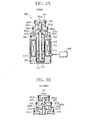
- FIGS. 2A and 2B show the structure of a displacement control valve 300 in a first embodiment of the present invention. Specifically, FIG. 2A is a cross-sectional view showing the whole valve in an open state, while FIG. B is a cross-sectional view partly showing the valve in a closed state.
- the displacement control valve 300 consists of a valve unit and a drive unit (solenoid) opening and closing the valve unit.
- the valve unit includes an approximately cylindrical valve housing 301, and inside the valve housing 301, a valve chamber 301b and a pressure sensing chamber 301e are defined to be in line along the axis of the valve housing 301.
- the valve housing 301 has a connection hole 301c and a connection hole 301f in the cylindrical wall, and a valve hole 301a at an end.
- the valve chamber 301b is connected to the discharge chamber 120 by the valve hole 301a and the upstream side of the gas supply passage 125, and to the crank chamber 105 by the connection hole 301c and the downstream side of the gas supply passage 125.
- the pressure sensing chamber 301e is connected to the suction chamber 119 by the connection hole 301f and the pressure sensing passage 127.
- An insertion hole 301d is provided through the center of the valve housing 301.
- the insertion hole 301d extends between the valve chamber 301b and the pressure sensing chamber 301e along the axis of the valve housing 301.
- a valve element 302 is inserted in the insertion hole 301d. The valve element 302 is thus slidably arranged inside the valve housing 301.
- a first end of the valve element 302 is located in the valve chamber 301b, while the opposite, second end is located in the pressure sensing chamber 301e.
- the valve element 302 opens and closes the valve hole 301a at the first end side, thereby opening and closing the gas supply passage 125.
- a compression coil spring 303 is arranged in the pressure sensing chamber 301e. Specifically, the compression coil spring 303 is arranged with a first end butted against the inner wall surface of the pressure sensing chamber 301e and the opposite, second end butted against a stepped portion 302a of the valve element 302 to push on the valve element 302 in a valve opening direction.
- the solenoid comprises a solenoid rod 310, a fixed core 311, a movable core 312, a tubular member 313, a compression coil spring 314, a support member 315, a molded coil 316 and a solenoid housing 317.
- the solenoid housing 317 is approximately cylindrical in shape and coaxially joined to the valve housing 301.
- the fixed core 311 is approximately cylindrical in shape and arranged inside the solenoid housing 317.
- the solenoid rod 310 is inserted in the fixed core 311.
- the solenoid rod 310 is arranged with a first end butted against the valve element 302 and the opposite, second end projecting beyond the fixed core 311.
- the second-end-side projecting portion of the solenoid rod 310 is passed through the movable core 31 approximately cylindrical in shape so that the movable core 312 is fixed on the solenoid rod 310.
- the movable core 312 faces the fixed core 311 with a predetermined space between.
- the tubular member 313 is fixed inside the solenoid housing 317 to enclose the movable core 312, the compression coil spring 314 and the support member 315 as well as part of the solenoid rod 310 and part of the fixed core 311.
- the support member 315 is approximately in the shape of a disc and arranged inside the tubular member 313 such that the movable core 312 is sandwiched between the support member and the fixed core 311.
- the compression coil spring 314 is arranged between the support member 315 and the movable core 312 to push on the movable core 312 toward the valve housing 301, and thus, push on the solenoid rod 310 and the valve element 302 in a valve closing direction.
- the fixed core 311 has a projecting portion 311a.
- the projecting portion 311a has an insertion hole 311b to allow the solenoid rod 310 to pass through.
- a connection hole 311c connects the space holding the movable core 312 to the pressure sensing chamber 301e.
- the solenoid rod 310 is arranged with a first end portion passed through the insertion hole 311b and the opposite second end on the support member 315, to be movable along the axis. It is arranged such that the outer circumferential surface of the movable core 312 does not touch the inner circumferential surface of the tubular member 313.
- the movable core 312, the fixed core 311 and the solenoid housing 317 are each made of a magnetic material and constitute a magnetic circuit.
- the tubular member 313 is made of a stainless-based nonmagnetic material.
- a control device 400 provided outside the compressor 100 is connected to the molded coil 314. Supplied with a control current I from the control device 400, the solenoid including the molded coil 314 generates an electromagnetic force F(I). The electromagnetic force F(I) generated by the solenoid attracts the movable core 312 toward the fixed core 310, thus acts on the valve element 302 in the valve closing direction.
- discharge pressure Pd acts on the first end of the valve element 302
- suction pressure Ps acts on the second end of the valve element 302.
- the valve element 302 thus functions also as a pressure sensing member moving in response to an acting pressure difference ⁇ P, namely pressure difference between the discharge pressure Pd and the suction pressure Ps.
- f3 is the force exerted by the compression coil spring 303
- f4 is the force exerted by the compression coil spring 31
- a ⁇ I is the electromagnetic force generated by the solenoid.
- A is a constant, and the solenoid is designed to generate the electromagnetic force in proportion to the control current I.
- the force f3 exerted by the compression coil spring 303 is slightly less than the force f4 exerted by the compression coil spring 314, so that f3-f 4 ⁇ 0. Consequently, when the electromagnetic force generated by the solenoid is 0, the valve element 302 is forced to close the valve hole 301a by the compression coil spring 314.
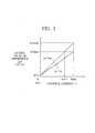
- FIG. 3 is the graph showing the relationship between the control current I and the acting pressure difference ⁇ P represented by equation (5).
- the maximum acting pressure difference ⁇ Pmax for the prior art is achieved by a control current value Imax' less than the control current value Imax in the prior art, resulting in a reduction in power consumption.
- the maximum control current value Imax for the prior art brings about a maximum acting pressure difference ⁇ Pmax' in the present case, which is greater than the maximum acting pressure difference ⁇ Pmax that the same control current value brings about in the prior art.
- the discharge pressure Pd receiving surface area Sv' of the valve element 302 is allowed to be greater than Sv. This results in higher sensitivity in responding to variations in acting pressure difference ⁇ P, namely difference between the discharge pressure Pd and the suction pressure Ps, and thus, provides improved control stability.
- the valve element 302 moves to open the valve, namely allow a flow from the discharge chamber 120 to the crank chamber 125 via the connection passage 125, so that the discharged gas is introduced to the crank chamber 105. Since the fixed orifice 103c restricts the flow from the crank chamber 105 to the suction chamber 119, the discharged gas entering the crank chamber 105 causes an increase in crank pressure Pc, and thus a reduction in inclination angle of the swashplate 107, and therefore, a reduction in displacement.
- the valve element 302 moves in the valve closing direction to restrict the flow from the discharge chamber 120 to the crank chamber 105, so that the amount of the discharged gas introduced to the crank chamber 105 reduces. This results in a decrease in crank pressure Pc, and thus an increase in inclination angle of the swashplate 107, and therefore an increase in displacement.
- the displacement is autonomously controlled to maintain the acting pressure difference ⁇ P at the minimum acting pressure difference ⁇ P0.
- the minimum acting pressure difference ⁇ P0 is determined by the compression coil spring 303, the compression coil spring 314 and the discharge pressure Pd receiving surface area Sv' of the valve element 302.
- the minimum acting pressure difference ⁇ P0 is determined depending on the urging force which the urging means exerts on the valve element 302 in the valve closing direction.
- the acting pressure difference ⁇ P is optionally varied by regulating the control current I supplied to the solenoid, and the displacement is controlled to maintain the acting pressure difference ⁇ P at a desired value.
- the displacement is autonomously controlled to achieve a desired air-conditioned state.
- the displacement is autonomously controlled, which means that the electromagnetic force generated by the solenoid is made effective use of, from the value 0.
- the minimum acting pressure difference ⁇ PO is set to be less than the pressure difference ⁇ Pset set for the check valve 200 to open. Consequently, while the displacement of the compressor 100 is being controlled to maintain the acting pressure difference at the minimum acting pressure difference ⁇ P0, the check valve 200 does not open but stays closed. The discharged refrigerant therefore does not circulate in the circulation line 12 of the air conditioning system but circulates inside the compressor 100, which prevents the evaporator 18 from freezing. Thus, with the solenoid not being excited, the compression coil spring 314's urging on the valve element 302 in the valve closing direction does not entail a problem.
- FIG. 4 is a cross-sectional view showing the structure of a displacement control valve 350 in a second embodiment of the present invention.
- the valve housing 351 of the displacement control valve 350 in the present embodiment has a valve hole 351a connected to the discharge chamber 120, a valve chamber 351b in which a first end of a valve element 352 is located, and a connection hole 351c connected to the crank chamber 105.
- the valve element 352 slidably extends through an insertion hole 351d, and further extends through a pressure sensing chamber 351e to which the insertion hole 351d connects, at a second end side opposite to the aforementioned first end of the valve element 352.
- the pressure sensing chamber 351e is connected to the suction chamber 119 via a connection hole 351f.
- the valve element 352 is pressed into a movable core 353 at the second end side, so that the movable core 353 is fixed on the valve element 352.
- the valve element 352 thus extends through the movable core 353, and the second end portion of the valve element 352 is slidably received in a support hole of the fixed core 354.
- the unit consisting of the valve element 352 and the movable core 353 integrally combined is pushed on in a valve closing direction by a compression coil 355 arranged between the movable core 353 and the fixed core 354.
- the fixed core 354 is arranged to face the movable core 353 with a predetermined space between, and a tubular member 356 is arranged to enclose the fixed core 356 and the movable core 353.
- a molded coil 357 is arranged to surround the tubular member 356, and the solenoid housing 351 surrounds the molded coil 357.
- the movable core 353, the fixed core 354 and the solenoid housing 358 are each made of a magnetic material and constitute a magnetic circuit.
- the tubular member 356 is made of a stainless-based nonmagnetic material.
- the valve element 352 is arranged to extend through the insertion hole 351d at the first end side, and be received in the fixed core 354 at the second end side. It is arranged such that the outer circumferential surface of the movable core 353 does not touch the inner circumferential surfaces of the tubular member 356 and the solenoid housing 358.
- the valve housing 351 is pressed into the solenoid housing 258 at an end, thereby fixed to the end of the solenoid housing, so that the valve housing and 351 and the solenoid housing 358 are integrally combined to form a displacement control valve 350.
- Equation (7) can be rearranged into equation (8) giving acting pressure difference ⁇ P.
- f5 is a force exerted by the compression coil spring 355
- a ⁇ I is an electromagnetic force generated by the solenoid, where A is a constant.
- FIG. 5 is the graph showing the relationship between the control current I and the acting pressure difference ⁇ P represented by equation (8).
- the present embodiment is arranged such that, with no current being supplied to the solenoid, the acting pressure difference takes a maximum value ⁇ Pmax.
- the acting pressure difference ⁇ P reduces, which is because the electromagnetic force acts in a valve opening direction.
- the acting pressure difference ⁇ P becomes 0 at a maximum value Imax of control current.
- the displacement control valve 350 makes effective use of the electromagnetic force from its value 0, which makes the displacement control valve optimal for variable displacement compressors provided with an electromagnetic clutch.
- the value of suction pressure Ps can be obtained indirectly from equation (5) or (8). Consequently, if a discharge pressure detection means is provided in the air conditioning system to detect the discharge pressure Pd, the displacement control valve 300 or 350 can control the displacement to maintain the suction pressure Ps at a set value. Conversely, provided that the absolute value of suction pressure Ps for a specified value of control current I is obtained, the value of discharge pressure Pd can be obtained indirectly.
- valve element 302 and the solenoid rod 310 may be formed integrally.
- the compression coil springs 303 and 314 or the compression coil 355 constitutes a urging means urging on the valve element 302 or 351 to hold the valve element 302 or 351 in the valve closing position when the solenoid is not being excited.
- the structure of the urging means is however not restricted to these.
- the urging means may include a spring of a type other than the compression coil spring.
- the crank pressure Pc acts on the valve element 302 or 352.
- the pressure sensing member may consist of a small bellows, in which case the valve element 302 is connected to an end of the bellows so that the discharge pressure Pd acts on the bellows, while the solenoid rod 310 is connected to an inner end face of the bellows into which the suction pressure Ps is introduced.
- the movable core 312 may be arranged with its outer circumferential surface in contact with the inner circumferential surface of the tubular member 313.
- the compressor may be a variable displacement wobble-plate compressor or a variable displacement compressor driven by a motor.
- the present invention is also applicable to variable displacement compressors in which a restriction capable of varying the flow passage area or a restriction using a valve element controlled to open or close the flow passage is provided in the gas release passage 126.
- the refrigerant is not restricted to R134a; carbon dioxide or other novel refrigerants may be used.
Landscapes
- Engineering & Computer Science (AREA)
- Mechanical Engineering (AREA)
- General Engineering & Computer Science (AREA)
- Compressors, Vaccum Pumps And Other Relevant Systems (AREA)
- Compressor (AREA)
Applications Claiming Priority (2)
| Application Number | Priority Date | Filing Date | Title |
|---|---|---|---|
| JP2007258659 | 2007-10-02 | ||
| PCT/JP2008/067851 WO2009044781A1 (ja) | 2007-10-02 | 2008-10-01 | 可変容量圧縮機 |
Publications (3)
| Publication Number | Publication Date |
|---|---|
| EP2194273A1 true EP2194273A1 (de) | 2010-06-09 |
| EP2194273A4 EP2194273A4 (de) | 2010-12-29 |
| EP2194273B1 EP2194273B1 (de) | 2013-04-24 |
Family
ID=40526206
Family Applications (1)
| Application Number | Title | Priority Date | Filing Date |
|---|---|---|---|
| EP08835453.5A Not-in-force EP2194273B1 (de) | 2007-10-02 | 2008-10-01 | Verstellbarer verdichter |
Country Status (5)
| Country | Link |
|---|---|
| US (1) | US8500415B2 (de) |
| EP (1) | EP2194273B1 (de) |
| JP (1) | JP5430401B2 (de) |
| CN (1) | CN101815866B (de) |
| WO (1) | WO2009044781A1 (de) |
Cited By (1)
| Publication number | Priority date | Publication date | Assignee | Title |
|---|---|---|---|---|
| EP3012454A1 (de) * | 2014-10-08 | 2016-04-27 | TGK CO., Ltd. | Regelventil |
Families Citing this family (2)
| Publication number | Priority date | Publication date | Assignee | Title |
|---|---|---|---|---|
| US9063252B2 (en) | 2009-03-13 | 2015-06-23 | Saudi Arabian Oil Company | System, method, and nanorobot to explore subterranean geophysical formations |
| JP5697022B2 (ja) * | 2010-12-14 | 2015-04-08 | サンデン株式会社 | 可変容量圧縮機 |
Family Cites Families (10)
| Publication number | Priority date | Publication date | Assignee | Title |
|---|---|---|---|---|
| JPH06341378A (ja) | 1993-06-03 | 1994-12-13 | Tgk Co Ltd | 容量可変圧縮機の容量制御装置 |
| JP3783434B2 (ja) * | 1998-04-13 | 2006-06-07 | 株式会社豊田自動織機 | 容量可変型斜板式圧縮機、及び空調用冷房回路 |
| JP2001193640A (ja) | 1999-12-28 | 2001-07-17 | Saginomiya Seisakusho Inc | 容量可変型圧縮機用制御弁 |
| JP2002147350A (ja) * | 2000-11-10 | 2002-05-22 | Toyota Industries Corp | 容量可変型圧縮機の制御装置 |
| JP4070425B2 (ja) | 2001-01-19 | 2008-04-02 | 株式会社テージーケー | 冷凍サイクルの圧縮容量制御装置 |
| JP2003083243A (ja) * | 2001-09-05 | 2003-03-19 | Toyota Industries Corp | 容量可変型圧縮機の容量制御装置 |
| JP2003083244A (ja) * | 2001-09-06 | 2003-03-19 | Nippon Soken Inc | 斜板型可変容量圧縮機 |
| JP4446026B2 (ja) * | 2002-05-13 | 2010-04-07 | 株式会社テージーケー | 可変容量圧縮機用容量制御弁 |
| JP2006029150A (ja) * | 2004-07-13 | 2006-02-02 | Sanden Corp | クラッチレス可変容量斜板式圧縮機の容量制御弁 |
| JP2006097673A (ja) * | 2004-08-31 | 2006-04-13 | Tgk Co Ltd | 可変容量圧縮機用制御弁 |
-
2008
- 2008-10-01 WO PCT/JP2008/067851 patent/WO2009044781A1/ja not_active Ceased
- 2008-10-01 EP EP08835453.5A patent/EP2194273B1/de not_active Not-in-force
- 2008-10-01 US US12/680,846 patent/US8500415B2/en not_active Expired - Fee Related
- 2008-10-01 JP JP2009536072A patent/JP5430401B2/ja not_active Expired - Fee Related
- 2008-10-01 CN CN2008801105164A patent/CN101815866B/zh not_active Expired - Fee Related
Cited By (1)
| Publication number | Priority date | Publication date | Assignee | Title |
|---|---|---|---|---|
| EP3012454A1 (de) * | 2014-10-08 | 2016-04-27 | TGK CO., Ltd. | Regelventil |
Also Published As
| Publication number | Publication date |
|---|---|
| JPWO2009044781A1 (ja) | 2011-02-10 |
| EP2194273A4 (de) | 2010-12-29 |
| CN101815866B (zh) | 2012-07-04 |
| EP2194273B1 (de) | 2013-04-24 |
| WO2009044781A1 (ja) | 2009-04-09 |
| US20100215514A1 (en) | 2010-08-26 |
| JP5430401B2 (ja) | 2014-02-26 |
| US8500415B2 (en) | 2013-08-06 |
| CN101815866A (zh) | 2010-08-25 |
Similar Documents
| Publication | Publication Date | Title |
|---|---|---|
| US9518568B2 (en) | Swash plate type variable displacement compressor | |
| JP5235569B2 (ja) | 容量制御弁、可変容量圧縮機及び可変容量圧縮機の容量制御システム | |
| JP3728387B2 (ja) | 制御弁 | |
| US6585494B1 (en) | Variable-capacity control for refrigerating cycle without using a large pressure control valve | |
| EP0854288A2 (de) | Regelventil für einen Verdichter mit veränderlicher Förderleistung und Verfahren zur Herstellung | |
| EP1138946A2 (de) | Regelventil für einen Verdichter variabler Verdrängung | |
| JP2009057855A (ja) | 可変容量圧縮機 | |
| US6416297B1 (en) | Stopping means for preventing movement of the drive shaft of a variable displacement compressor | |
| EP1024286A2 (de) | Kontrollventil für einen verstellbaren Taumelscheibenverdichter | |
| US8506261B2 (en) | Displacement control system for variable displacement compressor | |
| EP2194273B1 (de) | Verstellbarer verdichter | |
| JP4436295B2 (ja) | 可変容量圧縮機 | |
| JP5270890B2 (ja) | 可変容量圧縮機のための容量制御システム | |
| EP1033489A2 (de) | Kontrollventil für variable Verdrängungskompressoren | |
| JP5118430B2 (ja) | 容量制御弁及びこれを用いた可変容量圧縮機 | |
| JP5075682B2 (ja) | 可変容量圧縮機の容量制御システム | |
| US20170211561A1 (en) | Variable displacement swash plate type compressor | |
| EP1207302A2 (de) | Regelventil für einen Verdichter variabler Verdrängung | |
| JP5142212B2 (ja) | 可変容量圧縮機 | |
| JP5149580B2 (ja) | 可変容量圧縮機のための容量制御弁、容量制御システム及び可変容量圧縮機 | |
| JP5260906B2 (ja) | 可変容量圧縮機の容量制御弁 | |
| JP2008128091A (ja) | クラッチレス可変容量圧縮機 | |
| JP2000274351A (ja) | 可変容量型圧縮機 | |
| JP2005054697A (ja) | 可変容量圧縮機 |
Legal Events
| Date | Code | Title | Description |
|---|---|---|---|
| PUAI | Public reference made under article 153(3) epc to a published international application that has entered the european phase |
Free format text: ORIGINAL CODE: 0009012 |
|
| 17P | Request for examination filed |
Effective date: 20100401 |
|
| AK | Designated contracting states |
Kind code of ref document: A1 Designated state(s): AT BE BG CH CY CZ DE DK EE ES FI FR GB GR HR HU IE IS IT LI LT LU LV MC MT NL NO PL PT RO SE SI SK TR |
|
| AX | Request for extension of the european patent |
Extension state: AL BA MK RS |
|
| A4 | Supplementary search report drawn up and despatched |
Effective date: 20101129 |
|
| DAX | Request for extension of the european patent (deleted) | ||
| 17Q | First examination report despatched |
Effective date: 20110906 |
|
| REG | Reference to a national code |
Ref country code: DE Ref legal event code: R079 Ref document number: 602008024134 Country of ref document: DE Free format text: PREVIOUS MAIN CLASS: F04B0027140000 Ipc: F04B0027180000 |
|
| RIC1 | Information provided on ipc code assigned before grant |
Ipc: F04B 27/18 20060101AFI20120424BHEP |
|
| GRAP | Despatch of communication of intention to grant a patent |
Free format text: ORIGINAL CODE: EPIDOSNIGR1 |
|
| GRAS | Grant fee paid |
Free format text: ORIGINAL CODE: EPIDOSNIGR3 |
|
| GRAA | (expected) grant |
Free format text: ORIGINAL CODE: 0009210 |
|
| AK | Designated contracting states |
Kind code of ref document: B1 Designated state(s): AT BE BG CH CY CZ DE DK EE ES FI FR GB GR HR HU IE IS IT LI LT LU LV MC MT NL NO PL PT RO SE SI SK TR |
|
| REG | Reference to a national code |
Ref country code: GB Ref legal event code: FG4D |
|
| REG | Reference to a national code |
Ref country code: CH Ref legal event code: EP |
|
| REG | Reference to a national code |
Ref country code: AT Ref legal event code: REF Ref document number: 608783 Country of ref document: AT Kind code of ref document: T Effective date: 20130515 |
|
| REG | Reference to a national code |
Ref country code: IE Ref legal event code: FG4D |
|
| REG | Reference to a national code |
Ref country code: DE Ref legal event code: R096 Ref document number: 602008024134 Country of ref document: DE Effective date: 20130620 |
|
| REG | Reference to a national code |
Ref country code: AT Ref legal event code: MK05 Ref document number: 608783 Country of ref document: AT Kind code of ref document: T Effective date: 20130424 |
|
| REG | Reference to a national code |
Ref country code: LT Ref legal event code: MG4D |
|
| REG | Reference to a national code |
Ref country code: NL Ref legal event code: VDEP Effective date: 20130424 |
|
| PG25 | Lapsed in a contracting state [announced via postgrant information from national office to epo] |
Ref country code: LT Free format text: LAPSE BECAUSE OF FAILURE TO SUBMIT A TRANSLATION OF THE DESCRIPTION OR TO PAY THE FEE WITHIN THE PRESCRIBED TIME-LIMIT Effective date: 20130424 Ref country code: AT Free format text: LAPSE BECAUSE OF FAILURE TO SUBMIT A TRANSLATION OF THE DESCRIPTION OR TO PAY THE FEE WITHIN THE PRESCRIBED TIME-LIMIT Effective date: 20130424 Ref country code: GR Free format text: LAPSE BECAUSE OF FAILURE TO SUBMIT A TRANSLATION OF THE DESCRIPTION OR TO PAY THE FEE WITHIN THE PRESCRIBED TIME-LIMIT Effective date: 20130725 Ref country code: SE Free format text: LAPSE BECAUSE OF FAILURE TO SUBMIT A TRANSLATION OF THE DESCRIPTION OR TO PAY THE FEE WITHIN THE PRESCRIBED TIME-LIMIT Effective date: 20130424 Ref country code: ES Free format text: LAPSE BECAUSE OF FAILURE TO SUBMIT A TRANSLATION OF THE DESCRIPTION OR TO PAY THE FEE WITHIN THE PRESCRIBED TIME-LIMIT Effective date: 20130804 Ref country code: PT Free format text: LAPSE BECAUSE OF FAILURE TO SUBMIT A TRANSLATION OF THE DESCRIPTION OR TO PAY THE FEE WITHIN THE PRESCRIBED TIME-LIMIT Effective date: 20130826 Ref country code: FI Free format text: LAPSE BECAUSE OF FAILURE TO SUBMIT A TRANSLATION OF THE DESCRIPTION OR TO PAY THE FEE WITHIN THE PRESCRIBED TIME-LIMIT Effective date: 20130424 Ref country code: IS Free format text: LAPSE BECAUSE OF FAILURE TO SUBMIT A TRANSLATION OF THE DESCRIPTION OR TO PAY THE FEE WITHIN THE PRESCRIBED TIME-LIMIT Effective date: 20130824 Ref country code: BE Free format text: LAPSE BECAUSE OF FAILURE TO SUBMIT A TRANSLATION OF THE DESCRIPTION OR TO PAY THE FEE WITHIN THE PRESCRIBED TIME-LIMIT Effective date: 20130424 Ref country code: NO Free format text: LAPSE BECAUSE OF FAILURE TO SUBMIT A TRANSLATION OF THE DESCRIPTION OR TO PAY THE FEE WITHIN THE PRESCRIBED TIME-LIMIT Effective date: 20130724 Ref country code: SI Free format text: LAPSE BECAUSE OF FAILURE TO SUBMIT A TRANSLATION OF THE DESCRIPTION OR TO PAY THE FEE WITHIN THE PRESCRIBED TIME-LIMIT Effective date: 20130424 |
|
| PG25 | Lapsed in a contracting state [announced via postgrant information from national office to epo] |
Ref country code: CY Free format text: LAPSE BECAUSE OF FAILURE TO SUBMIT A TRANSLATION OF THE DESCRIPTION OR TO PAY THE FEE WITHIN THE PRESCRIBED TIME-LIMIT Effective date: 20130424 Ref country code: BG Free format text: LAPSE BECAUSE OF FAILURE TO SUBMIT A TRANSLATION OF THE DESCRIPTION OR TO PAY THE FEE WITHIN THE PRESCRIBED TIME-LIMIT Effective date: 20130724 Ref country code: HR Free format text: LAPSE BECAUSE OF FAILURE TO SUBMIT A TRANSLATION OF THE DESCRIPTION OR TO PAY THE FEE WITHIN THE PRESCRIBED TIME-LIMIT Effective date: 20130424 Ref country code: LV Free format text: LAPSE BECAUSE OF FAILURE TO SUBMIT A TRANSLATION OF THE DESCRIPTION OR TO PAY THE FEE WITHIN THE PRESCRIBED TIME-LIMIT Effective date: 20130424 Ref country code: PL Free format text: LAPSE BECAUSE OF FAILURE TO SUBMIT A TRANSLATION OF THE DESCRIPTION OR TO PAY THE FEE WITHIN THE PRESCRIBED TIME-LIMIT Effective date: 20130424 |
|
| PG25 | Lapsed in a contracting state [announced via postgrant information from national office to epo] |
Ref country code: CZ Free format text: LAPSE BECAUSE OF FAILURE TO SUBMIT A TRANSLATION OF THE DESCRIPTION OR TO PAY THE FEE WITHIN THE PRESCRIBED TIME-LIMIT Effective date: 20130424 Ref country code: DK Free format text: LAPSE BECAUSE OF FAILURE TO SUBMIT A TRANSLATION OF THE DESCRIPTION OR TO PAY THE FEE WITHIN THE PRESCRIBED TIME-LIMIT Effective date: 20130424 Ref country code: SK Free format text: LAPSE BECAUSE OF FAILURE TO SUBMIT A TRANSLATION OF THE DESCRIPTION OR TO PAY THE FEE WITHIN THE PRESCRIBED TIME-LIMIT Effective date: 20130424 Ref country code: EE Free format text: LAPSE BECAUSE OF FAILURE TO SUBMIT A TRANSLATION OF THE DESCRIPTION OR TO PAY THE FEE WITHIN THE PRESCRIBED TIME-LIMIT Effective date: 20130424 |
|
| PG25 | Lapsed in a contracting state [announced via postgrant information from national office to epo] |
Ref country code: RO Free format text: LAPSE BECAUSE OF FAILURE TO SUBMIT A TRANSLATION OF THE DESCRIPTION OR TO PAY THE FEE WITHIN THE PRESCRIBED TIME-LIMIT Effective date: 20130424 Ref country code: IT Free format text: LAPSE BECAUSE OF FAILURE TO SUBMIT A TRANSLATION OF THE DESCRIPTION OR TO PAY THE FEE WITHIN THE PRESCRIBED TIME-LIMIT Effective date: 20130424 Ref country code: NL Free format text: LAPSE BECAUSE OF FAILURE TO SUBMIT A TRANSLATION OF THE DESCRIPTION OR TO PAY THE FEE WITHIN THE PRESCRIBED TIME-LIMIT Effective date: 20130424 |
|
| PLBE | No opposition filed within time limit |
Free format text: ORIGINAL CODE: 0009261 |
|
| STAA | Information on the status of an ep patent application or granted ep patent |
Free format text: STATUS: NO OPPOSITION FILED WITHIN TIME LIMIT |
|
| 26N | No opposition filed |
Effective date: 20140127 |
|
| REG | Reference to a national code |
Ref country code: DE Ref legal event code: R097 Ref document number: 602008024134 Country of ref document: DE Effective date: 20140127 |
|
| PG25 | Lapsed in a contracting state [announced via postgrant information from national office to epo] |
Ref country code: MC Free format text: LAPSE BECAUSE OF FAILURE TO SUBMIT A TRANSLATION OF THE DESCRIPTION OR TO PAY THE FEE WITHIN THE PRESCRIBED TIME-LIMIT Effective date: 20130424 |
|
| REG | Reference to a national code |
Ref country code: CH Ref legal event code: PL |
|
| GBPC | Gb: european patent ceased through non-payment of renewal fee |
Effective date: 20131001 |
|
| REG | Reference to a national code |
Ref country code: IE Ref legal event code: MM4A |
|
| PG25 | Lapsed in a contracting state [announced via postgrant information from national office to epo] |
Ref country code: LI Free format text: LAPSE BECAUSE OF NON-PAYMENT OF DUE FEES Effective date: 20131031 Ref country code: CH Free format text: LAPSE BECAUSE OF NON-PAYMENT OF DUE FEES Effective date: 20131031 Ref country code: GB Free format text: LAPSE BECAUSE OF NON-PAYMENT OF DUE FEES Effective date: 20131001 |
|
| REG | Reference to a national code |
Ref country code: FR Ref legal event code: ST Effective date: 20140630 |
|
| PG25 | Lapsed in a contracting state [announced via postgrant information from national office to epo] |
Ref country code: FR Free format text: LAPSE BECAUSE OF NON-PAYMENT OF DUE FEES Effective date: 20131031 |
|
| PG25 | Lapsed in a contracting state [announced via postgrant information from national office to epo] |
Ref country code: IE Free format text: LAPSE BECAUSE OF NON-PAYMENT OF DUE FEES Effective date: 20131001 |
|
| PG25 | Lapsed in a contracting state [announced via postgrant information from national office to epo] |
Ref country code: TR Free format text: LAPSE BECAUSE OF FAILURE TO SUBMIT A TRANSLATION OF THE DESCRIPTION OR TO PAY THE FEE WITHIN THE PRESCRIBED TIME-LIMIT Effective date: 20130424 |
|
| PG25 | Lapsed in a contracting state [announced via postgrant information from national office to epo] |
Ref country code: HU Free format text: LAPSE BECAUSE OF FAILURE TO SUBMIT A TRANSLATION OF THE DESCRIPTION OR TO PAY THE FEE WITHIN THE PRESCRIBED TIME-LIMIT; INVALID AB INITIO Effective date: 20081001 Ref country code: LU Free format text: LAPSE BECAUSE OF NON-PAYMENT OF DUE FEES Effective date: 20131001 |
|
| PG25 | Lapsed in a contracting state [announced via postgrant information from national office to epo] |
Ref country code: MT Free format text: LAPSE BECAUSE OF FAILURE TO SUBMIT A TRANSLATION OF THE DESCRIPTION OR TO PAY THE FEE WITHIN THE PRESCRIBED TIME-LIMIT Effective date: 20130424 |
|
| REG | Reference to a national code |
Ref country code: DE Ref legal event code: R082 Ref document number: 602008024134 Country of ref document: DE Representative=s name: PRUEFER & PARTNER MBB PATENTANWAELTE RECHTSANW, DE Ref country code: DE Ref legal event code: R081 Ref document number: 602008024134 Country of ref document: DE Owner name: SANDEN HOLDINGS CORPORATION, LSESAKI-SHI, JP Free format text: FORMER OWNER: SANDEN CORPORATION, ISESAKI-SHI, GUNMA-KEN, JP |
|
| PGFP | Annual fee paid to national office [announced via postgrant information from national office to epo] |
Ref country code: DE Payment date: 20211020 Year of fee payment: 14 |
|
| REG | Reference to a national code |
Ref country code: DE Ref legal event code: R081 Ref document number: 602008024134 Country of ref document: DE Owner name: SANDEN CORPORATION, ISESAKI-SHI, JP Free format text: FORMER OWNER: SANDEN HOLDINGS CORPORATION, LSESAKI-SHI, GUNMA, JP |
|
| REG | Reference to a national code |
Ref country code: DE Ref legal event code: R119 Ref document number: 602008024134 Country of ref document: DE |
|
| PG25 | Lapsed in a contracting state [announced via postgrant information from national office to epo] |
Ref country code: DE Free format text: LAPSE BECAUSE OF NON-PAYMENT OF DUE FEES Effective date: 20230503 |