EP2194284A2 - Wälzlagervorrichtung - Google Patents
Wälzlagervorrichtung Download PDFInfo
- Publication number
- EP2194284A2 EP2194284A2 EP09177894A EP09177894A EP2194284A2 EP 2194284 A2 EP2194284 A2 EP 2194284A2 EP 09177894 A EP09177894 A EP 09177894A EP 09177894 A EP09177894 A EP 09177894A EP 2194284 A2 EP2194284 A2 EP 2194284A2
- Authority
- EP
- European Patent Office
- Prior art keywords
- outer ring
- raceway groove
- ring raceway
- rolling elements
- inner ring
- Prior art date
- Legal status (The legal status is an assumption and is not a legal conclusion. Google has not performed a legal analysis and makes no representation as to the accuracy of the status listed.)
- Withdrawn
Links
- 238000005096 rolling process Methods 0.000 title claims abstract description 109
- 239000000314 lubricant Substances 0.000 claims abstract description 44
- 230000002093 peripheral effect Effects 0.000 claims abstract description 15
- 230000000717 retained effect Effects 0.000 claims description 16
- 230000003746 surface roughness Effects 0.000 claims description 3
- 239000004519 grease Substances 0.000 description 22
- 238000005520 cutting process Methods 0.000 description 9
- 238000000034 method Methods 0.000 description 6
- 238000004519 manufacturing process Methods 0.000 description 5
- 238000005498 polishing Methods 0.000 description 5
- 230000008878 coupling Effects 0.000 description 4
- 238000010168 coupling process Methods 0.000 description 4
- 238000005859 coupling reaction Methods 0.000 description 4
- 238000003780 insertion Methods 0.000 description 4
- 230000037431 insertion Effects 0.000 description 4
- 230000014759 maintenance of location Effects 0.000 description 3
- 239000004696 Poly ether ether ketone Substances 0.000 description 2
- 239000004734 Polyphenylene sulfide Substances 0.000 description 2
- 229910000831 Steel Inorganic materials 0.000 description 2
- 239000000463 material Substances 0.000 description 2
- -1 polybutylene terephthalate Polymers 0.000 description 2
- 229920002530 polyetherether ketone Polymers 0.000 description 2
- 229920000069 polyphenylene sulfide Polymers 0.000 description 2
- 239000011347 resin Substances 0.000 description 2
- 229920005989 resin Polymers 0.000 description 2
- 238000007789 sealing Methods 0.000 description 2
- 239000010959 steel Substances 0.000 description 2
- 239000004721 Polyphenylene oxide Substances 0.000 description 1
- 238000005219 brazing Methods 0.000 description 1
- 230000000694 effects Effects 0.000 description 1
- 230000005489 elastic deformation Effects 0.000 description 1
- 230000002349 favourable effect Effects 0.000 description 1
- 230000007774 longterm Effects 0.000 description 1
- 230000001050 lubricating effect Effects 0.000 description 1
- 238000003754 machining Methods 0.000 description 1
- 239000007769 metal material Substances 0.000 description 1
- 230000007935 neutral effect Effects 0.000 description 1
- 150000002825 nitriles Chemical class 0.000 description 1
- 229920006122 polyamide resin Polymers 0.000 description 1
- 229920001707 polybutylene terephthalate Polymers 0.000 description 1
- 229920000570 polyether Polymers 0.000 description 1
- 230000036316 preload Effects 0.000 description 1
- 239000007787 solid Substances 0.000 description 1
- 239000000725 suspension Substances 0.000 description 1
- 230000002123 temporal effect Effects 0.000 description 1
- 229920006259 thermoplastic polyimide Polymers 0.000 description 1
Images

Classifications
-
- F—MECHANICAL ENGINEERING; LIGHTING; HEATING; WEAPONS; BLASTING
- F16—ENGINEERING ELEMENTS AND UNITS; GENERAL MEASURES FOR PRODUCING AND MAINTAINING EFFECTIVE FUNCTIONING OF MACHINES OR INSTALLATIONS; THERMAL INSULATION IN GENERAL
- F16C—SHAFTS; FLEXIBLE SHAFTS; ELEMENTS OR CRANKSHAFT MECHANISMS; ROTARY BODIES OTHER THAN GEARING ELEMENTS; BEARINGS
- F16C33/00—Parts of bearings; Special methods for making bearings or parts thereof
- F16C33/30—Parts of ball or roller bearings
- F16C33/66—Special parts or details in view of lubrication
- F16C33/6603—Special parts or details in view of lubrication with grease as lubricant
- F16C33/6607—Retaining the grease in or near the bearing
- F16C33/6614—Retaining the grease in or near the bearing in recesses or cavities provided in retainers, races or rolling elements
-
- F—MECHANICAL ENGINEERING; LIGHTING; HEATING; WEAPONS; BLASTING
- F16—ENGINEERING ELEMENTS AND UNITS; GENERAL MEASURES FOR PRODUCING AND MAINTAINING EFFECTIVE FUNCTIONING OF MACHINES OR INSTALLATIONS; THERMAL INSULATION IN GENERAL
- F16C—SHAFTS; FLEXIBLE SHAFTS; ELEMENTS OR CRANKSHAFT MECHANISMS; ROTARY BODIES OTHER THAN GEARING ELEMENTS; BEARINGS
- F16C33/00—Parts of bearings; Special methods for making bearings or parts thereof
- F16C33/30—Parts of ball or roller bearings
- F16C33/58—Raceways; Race rings
- F16C33/583—Details of specific parts of races
- F16C33/585—Details of specific parts of races of raceways, e.g. ribs to guide the rollers
-
- F—MECHANICAL ENGINEERING; LIGHTING; HEATING; WEAPONS; BLASTING
- F16—ENGINEERING ELEMENTS AND UNITS; GENERAL MEASURES FOR PRODUCING AND MAINTAINING EFFECTIVE FUNCTIONING OF MACHINES OR INSTALLATIONS; THERMAL INSULATION IN GENERAL
- F16C—SHAFTS; FLEXIBLE SHAFTS; ELEMENTS OR CRANKSHAFT MECHANISMS; ROTARY BODIES OTHER THAN GEARING ELEMENTS; BEARINGS
- F16C19/00—Bearings with rolling contact, for exclusively rotary movement
- F16C19/02—Bearings with rolling contact, for exclusively rotary movement with bearing balls essentially of the same size in one or more circular rows
- F16C19/14—Bearings with rolling contact, for exclusively rotary movement with bearing balls essentially of the same size in one or more circular rows for both radial and axial load
- F16C19/18—Bearings with rolling contact, for exclusively rotary movement with bearing balls essentially of the same size in one or more circular rows for both radial and axial load with two or more rows of balls
- F16C19/181—Bearings with rolling contact, for exclusively rotary movement with bearing balls essentially of the same size in one or more circular rows for both radial and axial load with two or more rows of balls with angular contact
- F16C19/183—Bearings with rolling contact, for exclusively rotary movement with bearing balls essentially of the same size in one or more circular rows for both radial and axial load with two or more rows of balls with angular contact with two rows at opposite angles
- F16C19/184—Bearings with rolling contact, for exclusively rotary movement with bearing balls essentially of the same size in one or more circular rows for both radial and axial load with two or more rows of balls with angular contact with two rows at opposite angles in O-arrangement
- F16C19/186—Bearings with rolling contact, for exclusively rotary movement with bearing balls essentially of the same size in one or more circular rows for both radial and axial load with two or more rows of balls with angular contact with two rows at opposite angles in O-arrangement with three raceways provided integrally on parts other than race rings, e.g. third generation hubs
-
- F—MECHANICAL ENGINEERING; LIGHTING; HEATING; WEAPONS; BLASTING
- F16—ENGINEERING ELEMENTS AND UNITS; GENERAL MEASURES FOR PRODUCING AND MAINTAINING EFFECTIVE FUNCTIONING OF MACHINES OR INSTALLATIONS; THERMAL INSULATION IN GENERAL
- F16C—SHAFTS; FLEXIBLE SHAFTS; ELEMENTS OR CRANKSHAFT MECHANISMS; ROTARY BODIES OTHER THAN GEARING ELEMENTS; BEARINGS
- F16C2326/00—Articles relating to transporting
- F16C2326/01—Parts of vehicles in general
- F16C2326/02—Wheel hubs or castors
-
- F—MECHANICAL ENGINEERING; LIGHTING; HEATING; WEAPONS; BLASTING
- F16—ENGINEERING ELEMENTS AND UNITS; GENERAL MEASURES FOR PRODUCING AND MAINTAINING EFFECTIVE FUNCTIONING OF MACHINES OR INSTALLATIONS; THERMAL INSULATION IN GENERAL
- F16C—SHAFTS; FLEXIBLE SHAFTS; ELEMENTS OR CRANKSHAFT MECHANISMS; ROTARY BODIES OTHER THAN GEARING ELEMENTS; BEARINGS
- F16C33/00—Parts of bearings; Special methods for making bearings or parts thereof
- F16C33/30—Parts of ball or roller bearings
- F16C33/38—Ball cages
- F16C33/41—Ball cages comb-shaped
- F16C33/412—Massive or moulded comb cages, e.g. snap ball cages
- F16C33/414—Massive or moulded comb cages, e.g. snap ball cages formed as one-piece cages, i.e. monoblock comb cages
- F16C33/416—Massive or moulded comb cages, e.g. snap ball cages formed as one-piece cages, i.e. monoblock comb cages made from plastic, e.g. injection moulded comb cages
-
- F—MECHANICAL ENGINEERING; LIGHTING; HEATING; WEAPONS; BLASTING
- F16—ENGINEERING ELEMENTS AND UNITS; GENERAL MEASURES FOR PRODUCING AND MAINTAINING EFFECTIVE FUNCTIONING OF MACHINES OR INSTALLATIONS; THERMAL INSULATION IN GENERAL
- F16C—SHAFTS; FLEXIBLE SHAFTS; ELEMENTS OR CRANKSHAFT MECHANISMS; ROTARY BODIES OTHER THAN GEARING ELEMENTS; BEARINGS
- F16C43/00—Assembling bearings
- F16C43/04—Assembling rolling-contact bearings
- F16C43/06—Placing rolling bodies in cages or bearings
Definitions
- the invention relates to a rolling bearing device used in a vehicle, such as an automobile.
- a rolling bearing device is used in a vehicle, such as an automobile, in order to install a tire wheel or a brake disk.
- a known rolling bearing device includes an inner ring that is integrally rotatably provided on an axle and that fixes a tire wheel Or a brake disk and an outer ring that is located on a radially outer side of the inner ring and that is non-rotatably fixed to a vehicle body side via rolling elements (Japanese Patent Application Publication No. 2006-57686 ( JP-A-2006-57686 )).
- the invention provides a rolling bearing device that satisfies both durability and manufacturing cost requirements by providing a lubricant reservoir portion at part of a raceway groove.
- the rolling bearing device includes: an outer ring that has an outer ring raceway groove formed on an inner peripheral surface of the outer ring and a counter bore portion that is provided on an outer side of the outer ring raceway groove in an axial direction; an inner ring member that has an inner ring raceway groove formed on an outer peripheral surface of the inner ring member; and a plurality of rolling elements that are interposed between the outer ring raceway groove and the inner ring raceway groove so as to freely roll and that are in contact with the inner ring raceway groove of the inner ring member and the outer ring raceway groove of the outer ring at a predetermined contact angle, wherein a lubricant reservoir portion that stores lubricant is formed at an intermediate portion between the outer ring raceway groove and the counter bore portion.
- raceway surfaces with which the rolling elements substantially contact inside the counter bore portion may be reduced, and the lubricant reservoir portion may be arranged adjacent to the raceway surfaces.
- the amount of lubricant filled may be increased, and, in addition, lubricant stored in the lubricant reservoir portion easily spreads to the rolling elements.
- the lubricant reservoir portion does not require polishing. Therefore, it is possible to provide a rolling bearing device that satisfies both durability and manufacturing cost requirements.
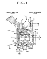
- FIG 1 is a cross-sectional view of an installed rolling bearing device according to the embodiment of the invention.
- the rolling bearing device 1 hub unit
- the rolling bearing device 1 includes an outer ring 2, an inner ring member 3 and rolling elements 4 so as to constitute a back-to-back double row angular contact ball bearing.
- the outer ring 2 serves as a fixed ring formed of bearing steel.
- the inner ring member 3 serves as a rotating ring.
- the rolling elements 4 formed of steel ball are interposed between the inner ring member 3 and the outer ring 2 and are arranged in double rows.
- a plurality of the rolling elements 4 are arranged in each row
- the rolling elements 4 are retained by a retainer 5 at equiangular intervals in the circumferential direction so as to be able to freely roll between the outer ring 2 and the inner ring member 3.
- the outer ring 2 is connected to a mounting port 7 of a vehicle fixed member 6, such as a vehicle inner side knuckle, axle housing, or the like, of a suspension in a vehicle.
- a radially outer side of the outer ring 2 is inserted and fitted in the mounting port 7, and an outer ring flange portion 8 extending from the outer ring 2 outward in the radial direction X is fixed to a peripheral surface (vehicle outer side) of the mounting port 7 of the vehicle fixed member 6 via a bolt 9.
- the inner peripheral surface of the outer ring 2 has parallel outer ring raceway grooves 11a and 11b so as to have a predetermined gap in the axial direction Z.
- the rolling elements 4 roll along the outer ring raceway grooves 11a and 11b.
- the outer ring raceway grooves 11a and 11b are formed in a circular arc shape with a curvature radius that is slightly larger than the curvature radius of each rolling element 4.
- An outer ring-side shoulder portion 10 is formed between the outer ring raceway groove 11a and the outer ring raceway groove 11b. The outer ring-side shoulder portion 10 protrudes inward in the radial direction X to have a reduced diameter.
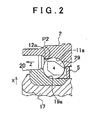
- counter bore portions 12a and 12b are provided respectively on the outer sides of the both outer ring raceway grooves 11a and 11b in the axial direction Z.
- the inside diameter of each of the counter bore portions 12a and 12b is larger than the inside diameter of the outer ring-side shoulder portion 10 in order to use the counter bore portions 12a and 12b in a process in which the plurality of rolling elements 4 retained by the retainer 5 are assembled into the outer ring raceway grooves 11a and 11b.
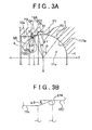
- the outer ring raceway groove 11a for forming the gap has a circular arc raceway surface 111a that extends from the connecting point P1 in the axial direction Z and that includes a contact portion T with which the rolling elements 4 contact.
- a terminal point P2 is located closer to the counter bore portion 12a than the connecting point P1 and is located inward in the radial direction X with respect to the connecting point P1.
- An intermediate portion between the terminal point P2 and the connecting point P1 is formed as the wall surface 12A.
- the wall surface 12A has a circular arc surface R1, a cylindrical surface portion 12C and a tapered surface portion 12B from the connecting point P1 outward in the axial direction Z toward the terminal point P2.
- the circular arc surface R1, the cylindrical surface portion 12C and the tapered surface portion 12B will be described in detail.
- the circular arc surface R1 having a predetermined circular arc length RL is formed continuously from the connecting point P1 outward in the axial direction Z (left side in FIG. 3A and FIG 3B ).
- the circular arc surface R1 has the same center of curvature as the center of curvature of the raceway surface 111a.
- the circular arc surface R1 serves as a restricting surface that restricts the rolling elements 4 that are retained by the retainer 5 in a loose fit manner and that are not in contact with the outer ring raceway groove 11 a at a predetermined contact pressure from coming off outward in the axial direction Z (counter bore portion 12a side).
- an imaginary reference circular arc surface SR that is extended from an end at the outer side of the circular arc surface R1 in the axial direction Z outward in the axial direction Z and that has the same center of curvature as the center of curvature of the circular arc surface R1 and an imaginary cylindrical surface LR that is extended from an end at the inner side of the counter bore portion 12a in the axial direction Z inward in the axial direction Z are assumed.
- a predetermined gap L is formed between the reference circular arc surface SR and imaginary cylindrical surface LR and the wall surface 12A and cylindrical surface portion 12C that face the surfaces SR and LR in the radial direction X, and the gap L serves as a lubricant reservoir portion GP in which grease serving as lubricant is stored.
- an angle ⁇ 1 within which the circular arc surface R1 is formed desirably ranges from 0 degrees to 15 degrees (see FIG. 3A ). This is because, when the angle ⁇ 1 is smaller than 0 degrees, a contact ellipse (contact point between the raceway surface 111a and the rolling surface of each rolling element 4) runs on an edge portion 12C1 of the cylindrical surface portion 12C, which will be described later, (shoulder overriding), and there is a possibility that the service life becomes short contrarily. Therefore, the circular arc surface R1 is formed continuously (at 0 degrees) from the connecting point P1 to eliminate the possibility of shoulder overriding.
- the wall surface 12A that forms the lubricant reservoir portion GP may be formed by cutting using a cutter, such as a so-called tool, and is a non-polished surface without polishing.
- the raceway surface 111a of the outer ring raceway groove 11a and the circular arc surface R1 are polished surfaces by polishing in order to make the rolling elements 4 scratch-proof when the raceway surface 111 a and the rolling elements 4 contact with each other at a predetermined contact pressure or when the circular arc surface R1 and the rolling elements 4 contact with each other so as to restrict the rolling elements 4 from coming off outward in the axial direction Z.
- the non-polished surface has a surface roughness that is higher than that of the polished surface.
- an inclined angle ⁇ 2 of the tapered surface portion 12B desirably ranges from 25 degrees to 35 degrees with the center of that angle at the intersection of the cylindrical surface portion 12C and the tapered surface portion 12B (see FIG 3B ). This is because the grease retention is better when the inclined angle ⁇ 2 is larger than or equal to 40 degrees (because a bag shape may be formed between the adjacent rolling elements 4); however, when the outer ring 2 is bored, it is impossible to continuously machine the raceway surface 111a, the circular arc surface R1, the cylindrical surface portion 12C, the tapered surface portion 12B and the counter bore portion 12a in the stated order using a bore cutting tool (brazing tool, solid tool, throw away tool, or the like) that serves as a tool.
- a bore cutting tool brazing tool, solid tool, throw away tool, or the like
- the bore cutting tool has a form such that a cutting edge protrudes when the inclined angle ⁇ 2 is large. Therefore, the tapered surface portion 12B interferes with portions other than the cutting edge of a cutting chip, the head of a tool to which the cutting chip is mounted, or the like, when the bore cutting tool is, for example, a throw away tool. For this reason the inclined angle ⁇ 2 is set so that continuous machining may be substantially performed in the above described order and no interference with a tool occurs.
- the inclined angle ⁇ 2 when the inclined angle ⁇ 2 is too small, grease is easily drained.
- the inclined angle ⁇ 2 that give a reasonable and effective shape is desirably about 30 degrees.
- the distance L between the reference circular arc surface SR and the tapered surface portion 12B is desirably smaller than or equal to 1.5 mm (see FIG. 3A ).
- a specific example of the distance L is a distance between the tapered surface portion 12B and a contact point LP of the reference circular arc surface SR and the imaginary cylindrical surface LR on a line that passes through both the center of a selected reference circular arc surface SR and the contact point LP. This is to improve grease retention and grease supply (because grease is hard to be drained, and grease is retained near the rolling elements 4 or the raceway surface 111a).
- it is not desirable that the distance L is smaller than or equal to 0 mm because there is a possibility that interference with the rolling elements 4 occurs.
- grease retained in the lubricant reservoir portion OP may run off outside the region surrounded by the above described reference circular arc surface SR, imaginary cylindrical surface LR, wall surface 12A and cylindrical surface portion 12C.
- a specific example of a form of the wall surface 12A of the lubricant reservoir portion GP is formed to have the tapered surface portion 12B and the cylindrical surface portion 12C.
- the tapered surface portion 12B has a reduced diameter form continuous from the terminal point P2 of the wall surface 12A.
- the cylindrical surface portion 12C is continuous from an end of the tapered surface portion 12B in the axial direction Z. Note that the cylindrical surface portion 12C is continuous with the circular arc surface R1.
- a wall surface having the same shape as the wall surface 12A is also formed on the vehicle outer side of the outer ring 2; however, the wall surface formed on the vehicle outer side and the wall surface 12A formed on the vehicle inner side are, of course, bilaterally symmetrical,
- the inner ring member 3 is integrally formed with a disk-shaped hub flange 14 that protrudes outward in the radial direction X.
- a hub bolt 15 is fixed to the hub flange 14.
- the hub bolt 15 is used to mount the hub flange 14 so as to be connected to a wheel (not shown) on the vehicle outer side.
- the hub bolt 15 is fixedly press-fitted into a bolt fitting hole 16 of the hub flange 14.
- the hub flange 14 is integrally formed on an outer periphery of one end (vehicle outer side) of a shaft portion 17 that constitutes part of the inner ring member 3 so as to protrude outward in the radial direction.
- a small-diameter portion 18 having a further small outside diameter is formed at the other end (vehicle inner side (left side in FIG. 1 )) of the shaft portion 17.
- An inner ring 20 is fixedly press-fitted into the small-dianeter portion 18.
- the inner ring 20 is separately formed from the small-diameter portion 18.
- the inner ring 20 has an inner ring raceway groove 19a on its outer peripheral surface.
- One of sets of the rolling elements 4 arranged in a plurality of rows roll on the inner ring raceway groove 19a.
- an inner ring raceway groove 19b is formed on an outer peripheral surface between the one end and the other end of the shaft portion 17.
- the other one of sets of the rolling elements arranged in a plurality of rows roll on the inner ring raceway groove 19b.
- the inner ring 20 is press-fitted to the other end of the shaft portion 17 to be integrated.
- the inner ring member 3 having the hub flange 14 at one end is formed.
- the inner ring raceway grooves 19a and 19b are also formed in a circular arc shape with a curvature radius that is slightly larger than the curvature radius of each rousing element 4, as in the case of the outer ring raceway grooves 11a and 11b of the outer ring 2.
- the shaft portion 17 of the inner ring member 3 has a coupling insertion hole 22 that serves as a spline hole.
- a drive shaft 21 that transmits power is spline-coupled to the coupling insertion hole 22.
- a spline shaft 23 of the drive shaft 21 is inserted into the coupling insertion hole 22 so that power is transmittable.
- a nut 26 that serves as a screw fastener is screwed to fix an end surface 24 of the drive shaft 21 to an extended side end of the drive shaft 21 so that the end surface 24 is in contact with a vehicle inner side inner ring end surface 25 of the inner ring 20, facing the end surface 24.
- a predetermined load is applied in the axial direction Z to bring the rolling surface of each rolling element 4 retained by the retainer 5 into contact with the outer ring raceway grooves 11a and 11b and the inner ring raceway grooves 19a and 19b at a predetermined contact angle ⁇ (see FIG. 3A and FIG. 3B ) with respect to the radial direction X.
- a predetermined contact pressure is preloaded on those contact portions.
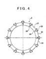
- the retainer 5 that retains the rolling elements 4 in a loose fit manner has an annular ring-shaped portion 27 that is placed in the space between the outer ring 2 and the inner ring member 3, and taper portions 28 are integrally formed with an end of the ring-shaped portion 27.
- Each taper portion 28 increases its diameter in the radial direction X as it protrudes in the axial direction Z.
- the taper portions 28 are formed to protrude so as to apply appropriate elasticity to a pair of retaining pawls 29 that face in the circumferential direction at constant intervals.
- the retaining pawls 29 are curved toward the adjacent retaining pawls 29.
- the retaining pawls 29 form concave spherical pocket portions 30 between the pairs of retaining pawls 29 and the ring-shaped portion 27.
- Each pocket portion 30 has a curvature radius that is slightly larger than the curvature radius of each rolling element 4.
- the retaining pawls 29 are elastically deformed to mount the rolling elements 4, and the rolling elements 4 are retained via predetermined pocket gaps.
- the retainer 5 forms a snap-on type crown-shaped retainer. By so doing, the rolling elements 4 may be retained so as not to come off.
- a metal material or a resin material may be used for the retaining pawls 29 of the retainer 5.
- a metal material or a resin material may be used for the retaining pawls 29.
- An example of the resin material includes polyamide resin, polybutylene terephthalate, polyphenylene sulfide (PPS), polyamide-umde (PAI), thermoplastic polyimide, polyether ether ketone (PEEK), polyether nitrile (PEN), or the like.
- the rolling elements 4 are assembled to the pocket portions 30 of the retainer 5 to form a subassembly in advance, and the subassembly is assembled from an outer side of the outer ring 2 in the axial direction Z (counter bore portions 12a and 12b side) into the outer ring raceway grooves 11a and 11b.
- the retaining pawls 29 of the retainer 5 have elasticity Therefore, when the rolling elements 4 run over the counter bore portion 12a (terminal point P2 of the wall surface 12A) shown in FIG 2 , the retaining pawls 29 elastically reduce their diameters (inward in the radial direction X) to allow the rolling elements 4 to be assembled into the outer ring raceway groove 11a. After that, the retaining pawls 29 elastically return to a neutral state (free state) before elastic deformation, and the rolling elements 4 retained in that state are retained in a loose fit manner.
- the rolling elements 4 are restricted by the restricting surface (the circular arc surface R1 or the wall surface 12A) of the counter bore portion 12a, and the subassembly that includes the mounted rolling elements 4 may be retained so that the subassembly does not come off from the outer ring raceway groove 11a.
- sealing devices 31a and 31b are arranged respectively at the vehicle outer side (right side in FIG.
- the above embodiment is the rolling bearing device 1 for a drive wheel.
- the rolling bearing device 1 may be used for a driven wheel in such a manner that the other end of the shaft portion 17 is extended to the outside, the other end is plastically deformed outward in the radial direction X so as to be calked to form a calked portion, and then the inner ring 20 is fixed so as not to come off in the axial direction Z.
- the rolling elements 4 are retained by the retaining pawls 29 of the retainer 5 to form a subassembly.
- Two sets of the subassembly are prepared respectively for the vehicle inner side and the vehicle outer side.
- Two sets of the subassembly are respectively inserted from both ends of the outer ring 2 in the axial direction Z (counter bore portions 12a and 12b side) to assemble the rolling elements 4 into the outer ring raceway grooves 11a and 11b.
- the shaft portion 17 of the inner ring member 3 is inserted from the vehicle outer side into an assembly of the outer ring 2 and two sets of subassembly, and then the inner ring 20 is inserted from the vehicle inner side into the small-diameter portion 18.
- the rolling elements 4 retained by the retainer 5 are assembled between the outer ring raceway grooves 11a and 11b of the outer ring 2 and the inner ring raceway grooves 19a and 19b of the inner ring member 3.
- the rolling bearing device 1 is used for a drive wheel
- the drive shaft 21 is fastened.
- the inner ring 20 is calked.
- the rolling bearing device 1 is assembled so as to apply a preload on the rolling elements 4 so that the rolling elements 4 are in contact with the outer ring raceway grooves 11a and 11b of the outer ring 2 and the inner ring raceway grooves 19a and 19b at a predetermined contact pressure.
- grease is supplied from the counter bore portion 12a side located on the vehicle inner side to fill grease into the space between the outer ring 2 and the inner ring member 3.
- grease is also stored in the lubricant reservoir portion GP and, particularly, the amount of grease stored may be increased at a portion adjacent to each rolling element 4.
- grease may be filled into the lubricant reservoir portion GP in a temporal assembly such that the rolling elements 4 of the subassembly are assembled into the outer ring raceway grooves 11 a and 11b of the outer ring 2.
- the rolling bearing device includes: an outer ring that has an outer ring raceway groove that is formed on an inner peripheral surface of the outer ring and a counter bore portion that is provided on an outer side of the outer ring raceway groove in an axial direction; an inner ring member that has an inner ring raceway groove that is formed on an outer peripheral surface of the inner ring member; and a plurality of rolling elements that are interposed between the outer ring raceway groove and the inner ring raceway groove so as to freely roll and that are in contact with the inner ring raceway groove of the inner ring member and the outer ring raceway groove of the outer ring at a predetermined contact angle, wherein a lubricant reservoir portion that stores lubricant is formed at an intermediate portion between the outer ring raceway groove and the counter bore portion.
- raceway surfaces with which the rolling elements substantially contact on the inner side of the counter bore portion may be reduced, and the lubricant reservoir portion may be arranged adjacent to the raceway surfaces.
- the amount of lubricant filled may be increased, and, in addition, lubricant stored in the lubricant reservoir portion easily spreads to the rolling elements.
- the lubricant reservoir portion does not require polishing. Therefore, it is possible to provide a rolling bearing device that satisfies both durability and manufacturing cost requirements.
- the lubricant reservoir portion is formed by increasing the diameter of the intermediate portion between the outer ring raceway groove and the counter bore portion outward in the radial direction.
- the outer ring raceway groove has a circular arc raceway surface that includes a contact portion with which the rolling elements contact, the raceway surface is extended outward in the axial direction to form an imaginary circular arc surface that has the same center of curvature as the center of curvature of the raceway surface as an imaginary reference circular arc surface, the counter bore portion is extended toward an inner side in the axial direction to imaginarily form a cylindrical surface as an imaginary cylindrical surface, and the lubricant reservoir portion is formed by increasing the diameter of the intermediate portion in the radial direction with respect to the imaginary reference circular arc surface and the imaginary cylindrical surface.
- the rolling elements are inserted from an outer side in the axial direction into the outer ring raceway groove in a state where the rolling elements are respectively retained by pocket portions that are provided for an annular retainer in a circumferential direction of the retainer, the retainer is elastically reduced in diameter in the radial direction when the rolling elements run over the counter bore portion, the retainer elastically returns after the rolling elements run over the counter bore portion to assemble the rolling elements into the outer ring raceway groove.
- the rolling elements assembled into the outer ring raceway groove may be prevented by the counter bore portion from coming off even when the outer ring is in any positions in an assembling process thereafter.
- this subassembly state it is possible to reliably store lubricant in the lubricant reservoir portion, and it is possible to smoothly fill lubricant into the lubricant reservoir portion.
- a raceway surface that includes a contact portion of the outer ring raceway groove, with which the rolling elements contact is a polished surface
- the lubricant reservoir portion has a non-polished surface having a surface roughness that is higher than that of the raceway surface.
- the shape of the inner peripheral surface of the lubricant reservoir portion may have a tapered surface portion that is continuous from the terminal point of the wall surface and that has a reduced diameter and a cylindrical surface portion that is continuous from an end of the tapered surface portion in the axial direction.
- the lubricant reservoir portion may be formed of a forged surface directly or may be formed using low-cost cutting process.
- a rolling bearing device includes: an outer ring (2) that has outer ring raceway grooves (11a and 11b) formed on an inner peripheral surface of the outer ring (2) and a counter bore portion (12a) that is provided on an outer side of the outer ring raceway grooves (11a and 11b) in an axial direction; an inner ring member (3) that has inner ring raceway grooves (19a and 19b) formed on an outer peripheral surface of the inner ring member (3); and a plurality of rolling elements (4) that are interposed between the outer ring raceway grooves (11a and 11b) and the inner ring raceway grooves (19a and 19b) so as to freely roll and that are in contact with the inner ring raceway grooves of the inner ring member and the outer ring raceway grooves of the outer ring at a predetermined contact angle.
- a lubricant reservoir portion (GP) that stores lubricant is formed at a portion in the outer ring raceway grooves (11a and 11b) adjacent to the counter bore portion (12a).
Landscapes
- Engineering & Computer Science (AREA)
- General Engineering & Computer Science (AREA)
- Mechanical Engineering (AREA)
- Rolling Contact Bearings (AREA)
Applications Claiming Priority (2)
| Application Number | Priority Date | Filing Date | Title |
|---|---|---|---|
| JP2008309633 | 2008-12-04 | ||
| JP2009247324A JP2010156455A (ja) | 2008-12-04 | 2009-10-28 | 転がり軸受装置 |
Publications (2)
| Publication Number | Publication Date |
|---|---|
| EP2194284A2 true EP2194284A2 (de) | 2010-06-09 |
| EP2194284A3 EP2194284A3 (de) | 2013-09-18 |
Family
ID=42041671
Family Applications (1)
| Application Number | Title | Priority Date | Filing Date |
|---|---|---|---|
| EP09177894.4A Withdrawn EP2194284A3 (de) | 2008-12-04 | 2009-12-03 | Wälzlagervorrichtung |
Country Status (4)
| Country | Link |
|---|---|
| US (1) | US8591115B2 (de) |
| EP (1) | EP2194284A3 (de) |
| JP (1) | JP2010156455A (de) |
| CN (1) | CN101749326A (de) |
Families Citing this family (8)
| Publication number | Priority date | Publication date | Assignee | Title |
|---|---|---|---|---|
| JP5720262B2 (ja) * | 2011-01-20 | 2015-05-20 | 株式会社ジェイテクト | 車輪用転がり軸受装置 |
| CN102562789A (zh) * | 2011-12-20 | 2012-07-11 | 西安奥奈特固体润滑工程学研究有限公司 | 一种轿车前轮轮毂的双列圆锥滚子轴承的设计方法 |
| CN103206459A (zh) * | 2013-05-06 | 2013-07-17 | 无锡市第二轴承有限公司 | 高速精密组合轴承的外圈 |
| JP2014224592A (ja) * | 2013-05-17 | 2014-12-04 | 株式会社ジェイテクト | 玉軸受 |
| DE102013213332A1 (de) * | 2013-07-08 | 2015-01-08 | Schaeffler Technologies Gmbh & Co. Kg | Stützlagerung, insbesondere Laufrolle |
| JP6720525B2 (ja) * | 2015-12-25 | 2020-07-08 | 株式会社ジェイテクト | 軸受装置 |
| IT201800009709A1 (it) * | 2018-10-24 | 2020-04-24 | Skf Ab | Unita’ cuscinetto con gabbia di ritenzione |
| KR102624585B1 (ko) * | 2019-04-03 | 2024-01-15 | 주식회사 일진글로벌 | 톤휠 및 톤휠 장착부 구조가 개선된 휠베어링 |
Citations (2)
| Publication number | Priority date | Publication date | Assignee | Title |
|---|---|---|---|---|
| US3161448A (en) | 1963-07-05 | 1964-12-15 | Fafnir Bearing Co | Outer ring for antifriction bearing |
| JP2006057686A (ja) | 2004-08-18 | 2006-03-02 | Ntn Corp | 車両用軸受装置 |
Family Cites Families (18)
| Publication number | Priority date | Publication date | Assignee | Title |
|---|---|---|---|---|
| US3645592A (en) * | 1969-09-11 | 1972-02-29 | Gen Motors Corp | Lubricant circulating angular contact ball bearing |
| US4111501A (en) * | 1974-02-06 | 1978-09-05 | Skf Industrial Trading & Development Co., B.V. | Bearing cage |
| JPS55653Y2 (de) * | 1975-04-17 | 1980-01-10 | ||
| IT8453261U1 (it) | 1984-04-13 | 1985-10-13 | Riv Skf Officine Spa | Cuscinetto a sfere |
| JPH11108068A (ja) * | 1997-09-30 | 1999-04-20 | Ntn Corp | アンギュラ玉軸受 |
| ITTO980035A1 (it) | 1998-01-16 | 1999-07-16 | Skf Ind Spa | Cuscinetto di rotolamento con dispositivo di rilevamento della velocit a' di rotazione. |
| JP2002122149A (ja) * | 2000-10-12 | 2002-04-26 | Ntn Corp | アンギュラ玉軸受およびこれを用いた工作機械 |
| JP2002188646A (ja) * | 2000-12-20 | 2002-07-05 | Nsk Ltd | 転がり軸受及び軸受装置 |
| JP2004116715A (ja) | 2002-09-27 | 2004-04-15 | Koyo Seiko Co Ltd | 転がり軸受装置 |
| JP2005090658A (ja) * | 2003-09-18 | 2005-04-07 | Nsk Ltd | 転がり軸受 |
| DE102005009935A1 (de) | 2005-03-04 | 2006-09-07 | Schaeffler Kg | Radlageranordnung mit Stirnverzahnung |
| DE102005018616A1 (de) | 2005-04-21 | 2006-10-26 | Schaeffler Kg | Schrägkugellager mit Schmiermittelspeicher |
| JP4467070B2 (ja) | 2005-05-12 | 2010-05-26 | Ntn株式会社 | 車輪用軸受装置 |
| JP2008115955A (ja) * | 2006-11-06 | 2008-05-22 | Ntn Corp | プーリ支持軸受および電磁クラッチのプーリ支持構造 |
| JP2008121840A (ja) | 2006-11-14 | 2008-05-29 | Ntn Corp | 車輪用軸受装置 |
| WO2008056445A1 (en) | 2006-11-06 | 2008-05-15 | Ntn Corporation | Bearing device for wheel |
| JP4893282B2 (ja) * | 2006-12-07 | 2012-03-07 | 日本精工株式会社 | 軸受ユニット |
| JP2008240826A (ja) * | 2007-03-26 | 2008-10-09 | Ntn Corp | 玉軸受および保持器 |
-
2009
- 2009-10-28 JP JP2009247324A patent/JP2010156455A/ja active Pending
- 2009-11-27 US US12/591,677 patent/US8591115B2/en not_active Expired - Fee Related
- 2009-12-02 CN CN200910224393A patent/CN101749326A/zh active Pending
- 2009-12-03 EP EP09177894.4A patent/EP2194284A3/de not_active Withdrawn
Patent Citations (2)
| Publication number | Priority date | Publication date | Assignee | Title |
|---|---|---|---|---|
| US3161448A (en) | 1963-07-05 | 1964-12-15 | Fafnir Bearing Co | Outer ring for antifriction bearing |
| JP2006057686A (ja) | 2004-08-18 | 2006-03-02 | Ntn Corp | 車両用軸受装置 |
Also Published As
| Publication number | Publication date |
|---|---|
| CN101749326A (zh) | 2010-06-23 |
| JP2010156455A (ja) | 2010-07-15 |
| EP2194284A3 (de) | 2013-09-18 |
| US8591115B2 (en) | 2013-11-26 |
| US20100142875A1 (en) | 2010-06-10 |
Similar Documents
| Publication | Publication Date | Title |
|---|---|---|
| US8591115B2 (en) | Rolling bearing device | |
| EP1077142B1 (de) | Achsaggregat für ein Antriebsrad eines Fahrzeuges | |
| CN109312775B (zh) | 插槽组件和制造插槽组件的方法 | |
| US10746229B2 (en) | Wheel bearing sealing device and manufacturing method therefor | |
| US9624977B2 (en) | Cylindrical roller bearing | |
| US20080096715A1 (en) | Tapered roller bearing and differential gear apparatus | |
| EP2422995B1 (de) | Herstellungsverfahren für eine Fahrzeugnabeneinheit | |
| US8882359B2 (en) | Wheel rolling bearing unit | |
| CN105317847B (zh) | 滚动轴承密封装置的嵌件、密封装置、万向节和轴承衬套 | |
| WO2010147135A1 (ja) | 車輪用軸受 | |
| CN104204565A (zh) | 包括弹性可变形元件的滚动轴承组件及其制造方法 | |
| JP6007655B2 (ja) | 車輪用軸受装置 | |
| JP2015128924A (ja) | 軸受モジュール | |
| US20210010532A1 (en) | Bearing device for wheels | |
| JP2008100632A (ja) | 車輪用軸受装置 | |
| JP2005212713A (ja) | 車輪用軸受装置 | |
| JP2009275759A (ja) | 深溝玉軸受 | |
| JP5097479B2 (ja) | 車輪用軸受およびこれを備えた車輪用軸受装置 | |
| JP2009275799A (ja) | 深溝玉軸受 | |
| JP2017026061A (ja) | 車輪用軸受装置、車輪用軸受装置の加工方法および車輪用軸受装置の組立て方法 | |
| CN211778499U (zh) | 球窝组件和车辆中的实心车桥组件 | |
| KR101411611B1 (ko) | 실링 캡 및 이를 이용한 휠 베어링 조립체 | |
| US20100104232A1 (en) | Sealing device, rolling bearing, and rolling bearing for wheel | |
| JP4853622B2 (ja) | 車輪取付用転がり軸受装置 | |
| JP5891720B2 (ja) | ハブユニット軸受 |
Legal Events
| Date | Code | Title | Description |
|---|---|---|---|
| PUAI | Public reference made under article 153(3) epc to a published international application that has entered the european phase |
Free format text: ORIGINAL CODE: 0009012 |
|
| AK | Designated contracting states |
Kind code of ref document: A2 Designated state(s): AT BE BG CH CY CZ DE DK EE ES FI FR GB GR HR HU IE IS IT LI LT LU LV MC MK MT NL NO PL PT RO SE SI SK SM TR |
|
| AX | Request for extension of the european patent |
Extension state: AL BA RS |
|
| PUAL | Search report despatched |
Free format text: ORIGINAL CODE: 0009013 |
|
| AK | Designated contracting states |
Kind code of ref document: A3 Designated state(s): AT BE BG CH CY CZ DE DK EE ES FI FR GB GR HR HU IE IS IT LI LT LU LV MC MK MT NL NO PL PT RO SE SI SK SM TR |
|
| AX | Request for extension of the european patent |
Extension state: AL BA RS |
|
| RIC1 | Information provided on ipc code assigned before grant |
Ipc: F16C 33/41 20060101ALI20130814BHEP Ipc: F16C 33/66 20060101AFI20130814BHEP |
|
| 17P | Request for examination filed |
Effective date: 20131118 |
|
| 17Q | First examination report despatched |
Effective date: 20160909 |
|
| STAA | Information on the status of an ep patent application or granted ep patent |
Free format text: STATUS: THE APPLICATION IS DEEMED TO BE WITHDRAWN |
|
| 18D | Application deemed to be withdrawn |
Effective date: 20170120 |