EP2194296A2 - Système de lubrification pour train d'engrenages - Google Patents
Système de lubrification pour train d'engrenages Download PDFInfo
- Publication number
- EP2194296A2 EP2194296A2 EP09178086A EP09178086A EP2194296A2 EP 2194296 A2 EP2194296 A2 EP 2194296A2 EP 09178086 A EP09178086 A EP 09178086A EP 09178086 A EP09178086 A EP 09178086A EP 2194296 A2 EP2194296 A2 EP 2194296A2
- Authority
- EP
- European Patent Office
- Prior art keywords
- pair
- gears
- lubricating oil
- gear
- shroud
- Prior art date
- Legal status (The legal status is an assumption and is not a legal conclusion. Google has not performed a legal analysis and makes no representation as to the accuracy of the status listed.)
- Granted
Links
Images



Classifications
-
- F—MECHANICAL ENGINEERING; LIGHTING; HEATING; WEAPONS; BLASTING
- F16—ENGINEERING ELEMENTS AND UNITS; GENERAL MEASURES FOR PRODUCING AND MAINTAINING EFFECTIVE FUNCTIONING OF MACHINES OR INSTALLATIONS; THERMAL INSULATION IN GENERAL
- F16H—GEARING
- F16H57/00—General details of gearing
- F16H57/04—Features relating to lubrication or cooling or heating
- F16H57/048—Type of gearings to be lubricated, cooled or heated
- F16H57/0493—Gearings with spur or bevel gears
-
- F—MECHANICAL ENGINEERING; LIGHTING; HEATING; WEAPONS; BLASTING
- F16—ENGINEERING ELEMENTS AND UNITS; GENERAL MEASURES FOR PRODUCING AND MAINTAINING EFFECTIVE FUNCTIONING OF MACHINES OR INSTALLATIONS; THERMAL INSULATION IN GENERAL
- F16H—GEARING
- F16H57/00—General details of gearing
- F16H57/04—Features relating to lubrication or cooling or heating
- F16H57/0409—Features relating to lubrication or cooling or heating characterised by increasing efficiency, e.g. by reducing splash losses
-
- F—MECHANICAL ENGINEERING; LIGHTING; HEATING; WEAPONS; BLASTING
- F16—ENGINEERING ELEMENTS AND UNITS; GENERAL MEASURES FOR PRODUCING AND MAINTAINING EFFECTIVE FUNCTIONING OF MACHINES OR INSTALLATIONS; THERMAL INSULATION IN GENERAL
- F16H—GEARING
- F16H57/00—General details of gearing
- F16H57/04—Features relating to lubrication or cooling or heating
- F16H57/042—Guidance of lubricant
- F16H57/0421—Guidance of lubricant on or within the casing, e.g. shields or baffles for collecting lubricant, tubes, pipes, grooves, channels or the like
- F16H57/0423—Lubricant guiding means mounted or supported on the casing, e.g. shields or baffles for collecting lubricant, tubes or pipes
-
- F—MECHANICAL ENGINEERING; LIGHTING; HEATING; WEAPONS; BLASTING
- F16—ENGINEERING ELEMENTS AND UNITS; GENERAL MEASURES FOR PRODUCING AND MAINTAINING EFFECTIVE FUNCTIONING OF MACHINES OR INSTALLATIONS; THERMAL INSULATION IN GENERAL
- F16H—GEARING
- F16H57/00—General details of gearing
- F16H57/04—Features relating to lubrication or cooling or heating
- F16H57/0456—Lubrication by injection; Injection nozzles or tubes therefor
Definitions
- the present invention relates to a lubricating system for a gear train provided in a gear unit, such as a gear box, a high-speed gear mechanism or the like, used in a gas-turbine engine or jet engine.
- a gear unit such as a gear box, a high-speed gear mechanism or the like, used in a gas-turbine engine or jet engine.
- the gear unit of this type has a lubricating oil supply port provided for spraying lubricating oil toward each gear in order to lubricate and cool the gear, and a lubricating oil discharge port provided for recovering the lubricating oil remaining after a lubricating and cooling operation, with an oil-discharge pump.
- a lubricating oil supply port provided for spraying lubricating oil toward each gear in order to lubricate and cool the gear
- a lubricating oil discharge port provided for recovering the lubricating oil remaining after a lubricating and cooling operation, with an oil-discharge pump.
- the shroud of this system includes a pair of side walls, each opposed to a side face of each gear, while extending adjacent an outer diametrical face of the gear, and an end wall arranged to be vertical to the pair of side walls, while extending parallel to the front face of each gear.
- these side walls and end wall are respectively arranged to surround each front face of the plurality of gears in the gear train.
- a first opening for injecting the lubricating oil toward each gear and a second opening for discharging the lubricating oil from the shroud are provided in the end wall, respectively.
- the above shroud covering the respective gears in the gear train has a shape suitable for smoothly introducing the lubricating oil into the discharge port without causing undue residence of the lubricating oil and then efficiently discharging the lubricating oil from the discharge port. If the discharge port is provided in an unsuitable position of the shroud, the residence of an excessive amount of the lubricating oil would occur in the shroud, leading to substantial increase of the loss of power, irrespectively of the provision of the shroud. It is true that the shroud disclosed in the Patent Document 1 can positively control the generation of the aforementioned spiral air flow.
- the lubricating system for the gear train includes: a lubricating oil supply port configured to supply a lubricating oil in a direction vertical to both axes of a pair of gears and toward a mesh point at which the pair of gears are meshed with each other; a shroud configured to cover at least teeth of the pair of gears so as to form a flow passage of the lubricating oil between the pair of gears and the shroud; and a pair of discharge ports respectively configured to discharge the lubricating oil from the flow passage, the pair of discharge ports respectively being positioned at two portions of the shroud respectively opposed to the mesh point across respective axes of the pair of gears.
- the lubricating oil can be swirled at an appropriate speed along an inner face of the shroud, as well as the centrifugal force can be applied most effectively to such swirled lubricating oil. Therefore, even in the case in which the discharge ports respectively provided to such portions have a relatively small opening area that is advantageous for controlling the air resistance, the lubricating oil can be discharged in a preset discharge amount from each discharge port.
- the air resistance caused by the rotation of the gears can be securely reduced, as well as the increase of the resistance associated with stirring the lubricating oil, which would be otherwise caused by the undue residence of the lubricating oil in the shroud, can be successfully controlled.
- the pair of gears are bevel gears.
- the pair of discharge ports are respectively located in two positions respectively opposite to a pair of toothed portions of the pair of bevel gears in radially outward directions, each of the toothed portions including the teeth of each of the bevel gears and an annular rim of each of the bevel gears on which the teeth are formed.
- each bevel gear Since the teeth of each bevel gear have a truncated-cone-like shape on the whole, the lubricating oil swirled with the rotation of each gear tends to be gathered around the toothed portion composed of the truncated-cone-like teeth and rim, while being subjected to an effect of the centrifugal force for swirling the lubricating oil. Therefore, the discharge ports, each provided to be opposed to the toothed portion radially from the outside, can serve to discharge the lubricating oil with high efficiency.
- the shroud when the pair of gears are bevel gears, respectively, the shroud includes a pair of end walls respectively covering a pair of front faces of the pair of gears, a pair of partially cylindrical walls respectively covering a pair of outer circumferential faces of the pair of toothed portions from radially outsides, and a pair of partially conical walls respectively covering distal ends of the teeth from obliquely radially outsides.
- the pair of discharge ports are respectively formed in the pair of partially cylindrical walls.
- each discharge port can be provided in the position, in which the discharge port is opposed to the toothed portion radially from the outside and to which the centrifugal force for swirling the lubricating oil can be applied at the maximum effect. Therefore, the lubricating oil can be discharged more effectively.
- a width of each of the pair of discharge ports in an axial direction of each corresponding gear is substantially coincident with a height in the axial direction of each of the pair of partially cylindrical walls.
- the lubricating oil can be discharged efficiently from each discharge port provided over the entire height in the axial direction of each corresponding partially cylindrical wall.
- the pair of gears have horizontal axes, respectively, and the lubricating oil is supplied upward from below toward the mesh point.
- a position below the mesh point of the pair of gears respectively having the horizontal axes, i.e., a rear side in the respective rotational directions of the two gears, is a side that will be subjected to a gear pump effect.
- the lubricating oil can be smoothly supplied toward the mesh point from the position below the mesh point. Therefore, as compared with the case in which the lubricating oil is supplied to the mesh point, while being injected in a direction parallel to each gear axis from each front face side of the two gears, the lubricating oil can be supplied to the teeth of each gear more efficiently in a greater amount.
- each of the pair of discharge ports is located in a position angularly spaced apart from the mesh point by approximately 180° about an axis of each corresponding gear, and a circumferential length of each of the pair of discharge ports corresponds to a circumferential angle of approximately 30° about the axis of each corresponding gear.
- the flow of the lubricating oil can be sufficiently regulated by the shroud, as well as can be swirled at the appropriate speed, while being subjected to the centrifugal force.
- the lubricating oil can be smoothly discharged, in the preset discharge amount, from the discharge port. This can significantly reduce the resistance associated with stirring the lubricating oil.
- each discharge port is provided in a position angularly spaced apart from the mesh point by an angle less than 180°, the flow of the lubricating oil would not be sufficiently regulated, resulting in a poor effect of discharging the lubricating oil. Contrary, if each discharge port is provided in a position angularly spaced apart from the mesh point by an angle greater than 180°, the residence time of the lubricating oil in the shroud would be unduly long, resulting in increase of the resistance associated with stirring the lubricating oil.
- each discharge port is shorter than the length corresponding to the circumferential angle of 30°, the discharge amount of the lubricating oil would be reduced to be less than the preset amount, leading to the residence of the excessive amount of the lubricating oil in the shroud. Contrary, if the circumferential length of each discharge port is longer than the length corresponding to the circumferential angle of 30°, the air resistance would be unduly increased with the air flowed into the shroud from the discharge port.
- the shroud includes a pair of end walls respectively covering a pair of front faces of the pair of gears, and an inlet port for introducing an outside air into the shroud is formed in one of the pair of end walls at a position opposite to the front face of one gear having an outer diameter smaller than an outer diameter of an other gear.
- the effect of the centrifugal force applied from the outer circumferential face of the gear having the smaller outer diameter is less than the effect applied from the gear having the larger outer diameter, thus reducing the pump effect so much. Therefore, such a smaller outer diameter of the gear renders the lubricating oil unlikely to be flowed along the inner face of the shroud, leading to a poor discharge effect of the lubricating oil from the discharge port.
- the inlet port of this invention the air flowed into the shroud from the air inlet can adequately compensate for the pump effect reduced as described above, thereby smoothing the discharge of the lubricating oil.
- the lubricating oil can be smoothly swirled in such portions at an appropriate flow speed, while the centrifugal force can be applied to the swirled lubricating oil, most effectively, in a discharge direction. Therefore, even in the case in which the discharge port provided in each of the portions has such a relatively small opening area that can control the air resistance, the lubricating oil can be discharged in the preset discharge amount from the discharge port. This can significantly reduce both of the air resistance and resistance associated with stirring the lubricating oil.
- the gear unit includes the lubricating system according to the embodiment of the present invention.
- the present invention is applied to a gear box 1 that is one typical example of the gear unit.
- the gear box 1 includes a bearing housing 2, in which an input shaft 7 is rotatably supported by bearings 3, 4 and an output shaft 10 is rotatably supported by bearings 8, 9, respectively.
- An axis P1 of the input shaft 7 and an axis P2 of the output shaft 10 lie in the same plane, respectively. Further, in this example, the axes P1 and P2 are orthogonal relative to each other in the same horizontal plane.
- an input gear 11 composed of a bevel gear is integrally provided.
- the input gear 11 is projected toward one side of the bearing housing 2, while facing a gear space S in the gear box 1.
- the other end 7b of the input shaft 7 is connected with a power source, such as the jet engine or the like, via a mechanical reduction gear (not shown).
- an output gear 12 also composed of the bevel gear is integrally provided. This output gear 12 is projected toward another side of the bearing housing 2, while facing the gear space S in the gear box 1.
- the other end 10b of the output shaft 10 is connected with an auxiliary machine, such as a power generator or the like, via another mechanical reduction gear (not shown).
- the input gear 11 and output gear 12 both composed of the bevel gears, have the axes P1, P2 that are orthogonal relative to each other in the same horizontal plane, respectively. Further, the input gear 11 and output gear 12 are meshed with each other, while defining a 90° angle therebetween. Accordingly, a mesh point 13 of the two gears 11, 12 is in the horizontal plane including the two axes P1, P2. In this case, the two gears 11, 12 are rotated via the mesh point 13 in directions R1, R2, respectively. Therefore, a position below the mesh point 13 corresponds to a side or region subjected to a gear pump effect of the two gears 11, 12.
- both of the gears 11, 12 are surrounded by a shroud 14 attached to the bearing housing 2 via a plurality of bolts (not shown).
- the two gears 11, 12 include toothed portions 22, 23 and disks 24, 27, respectively.
- the toothed portions 22, 23 are integrally formed around outer circumferences of the disks 24, 27, respectively.
- the toothed portions 22, 23 are composed of teeth 18, 19 respectively constituting the bevel gears and annular rims 20, 21 respectively having the teeth 18, 19 formed thereon, respectively.
- front faces 11a, 12a of the two gears 11, 12 respectively facing the outside in the axial directions i.e., the faces of the two gears 11, 12 respectively opposed to the apexes of imaginary cones defined by the truncated-cone shaped teeth 18, 19 of the disks 24, 27, are formed into flat faces respectively extending in radial directions r1, r2.
- front end portions 22a, 23a of the toothed portions 22, 23 are projected forward relative to the gear front faces 11a, 12a, respectively.
- rear faces of the toothed portions 22, 23 are formed into inclined faces 22b, 23b respectively inclined radially inward as well as axially inward, respectively.
- the shroud 14 forms a flow passage 17 in a space provided between the two gears 11, 12.
- This flow passage 17 serves to supply the lubricating oil into the shroud 14 from a nozzle which will be described later.
- the shroud 14 includes first and second end walls 28, 29 respectively covering the gear front faces 11a, 12a of the two gears 11, 12; first and second partially cylindrical walls 30, 31 respectively covering outer circumferential faces 22d, 23d respectively including maximum diametrical portions 22c, 23c of the toothed portions 22, 23 of the two gears 11, 12, in the radial directions r1, r2 from the outside; first and second partially conical walls 32, 33 respectively covering distal ends of the teeth of the two gears 11, 12, obliquely to the radial directions r1, r2 from the outside; and first and second rear walls 34, 37 respectively extending inward in the radial directions r1, r2 of the two gears 11, 12 from corresponding axial ends of the partially cylindrical walls 30, 31, while covering the respective toothed portions 22,
- stepped portions 28a, 29a are provided along corresponding inner circumferential faces of the toothed portions 22, 23 of the gears 11, 12, respectively.
- each gap between the respective end walls 28, 29 and the corresponding gear front faces 11a, 12a can be positively reduced.
- relatively large oil reservoirs 41, 42 are provided, respectively.
- the pair of partially cylindrical walls 30, 31, respectively constituting the outer circumference of the shroud 14, are connected with each other via upper and lower non-cylindrical portions 43, 44 respectively covering the mesh point 13 of the two gears 11, 12. Except such connection portions, however, most of each partially cylindrical wall 30, 31 is formed into a cylindrical shape.
- the pair of partially conical walls 32, 33 are connected with each other via non-conical portions 47, 48 respectively covering the mesh point 13 of the two gears 11, 12. Except such connection portions, however, most of each partially conical wall 32, 33 has the truncated-cone-like shape.
- annular rear walls 34, 37 of the shroud 14 are also connected with each other via a non-annular portion 49 covering the mesh point 13 from the back side.
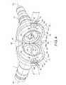
- an inlet port 29b for the air A is formed in a central portion of the end wall 29 covering the front face of the output gear 12 of the shroud 14 shown in Fig. 4 , i.e., in the central portion of the end wall 29 facing the front face of the output gear 12, an inlet port 29b for the air A is formed.
- a nozzle 38 adapted for supplying the lubricating oil OL is fixed in a position opposite, from below, to the mesh point 13 of the two gears 11, 12 of the shroud 14, while extending through the shroud 14 vertically upward. Accordingly, a lubricating oil supply port 38a provided at a distal end of the nozzle 38 is located just below the mesh point 13 of the two gears 11, 12. Thus, the nozzle 38 can supply the lubricating oil OL, upwardly from below, toward the mesh point 13. As described above, the position below the mesh point 13 corresponds to the side or region subjected to the gear pump effect that will be determined by the respective rotational directions R1, R2 of the two gears 11, 12. For this reason, the lubricating oil supply port 38a of the nozzle 38 is located just below the mesh point 13.
- first and second discharge ports 39, 40 for the lubricating oil OL are provided to portions respectively opposed to the mesh point 13 of the two gears 11, 12 across the axes P1, P2, or formed in positions angularly spaced apart from the mesh point 13 by an angle ⁇ of approximately 180° in the rotational directions R1, R2 about the respective axes P1, P2 of the two gears 11, 12, respectively.
- the positions of the discharge ports 39, 40 refer to the central positions, in both of the axial and circumferential directions, of the respective discharge ports 39, 40, respectively.
- the angle ⁇ is set within a range of 180° ⁇ 15°, more preferably 180° ⁇ 10°, and more preferably 180° ⁇ 5°.
- each discharge port 39, 40 When seen in the corresponding radial direction, each discharge port 39, 40 has a rectangular shape, and is set to have a circumferential length L that corresponds to a circumferential angle ⁇ of approximately 30° about each axis P1, P2.
- the circumferential angle ⁇ is within a range of 30° ⁇ 7°, more preferably 30° ⁇ 5°, and more preferably 30° ⁇ 3°.
- the width W in the direction of each axis P1, P2 of the discharge ports 39, 40 is set to be substantially coincident with the height h in the direction of each axis P1, P2 of the outer circumferential faces 22d, 23d of the respective toothed portions 22, 23.
- the width W is within a range of 0.9 to 1.1h.
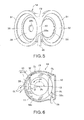
- Fig. 6 shows one typical operation for lubricating the input gear 11.
- the lubricating oil OL injected upward from the lubricating oil supply port 38a of the nozzle 38 is supplied to the mesh point 13 of the two gears 11, 12, so that the mesh point 13 can be lubricated with the lubricating oil OL.
- the lubricating oil OL supplied to the mesh point 13 is flowed upward due to a kind of gear pump effect generated by the rotation of the two gears 11, 12 in the shroud 14. Thereafter, the flow of the lubricating oil OL is bifurcated into two flows toward the two gears 11, 12, while being guided by the shroud 14.
- the lubricating oil supply port 38a is located on the side to be subjected to the gear pump effect. Therefore, as compared with the case in which the lubricating oil OL is horizontally injected and supplied toward the mesh point 13 from the front face side of the input gear 11, the lubricating oil OL can be supplied to the input gear 11 more efficiently, in a greater amount, by only adding a low level of discharging pressure to the oil by using a lubricating oil pump (not shown). Thus, the mesh point 13 can be lubricated enough with such efficiently supplied oil. Furthermore, the air is drawn by the centrifugal force into the shroud 14 from a gap G1 between the first rear wall 34 and the inclined face 22b of the toothed portion 22 shown in Fig. 3 , and then discharged to the exterior from the first discharge port 39 together with the lubricating oil OL, as shown in Fig. 6 .
- the provision of the stepped portion 28a to the first end wall 28 along the inner circumferential face of the toothed portion 22 of the input gear 11 can positively reduce the gap between the first end wall 28 and the gear front face 11a. Therefore, the spiral air flow AS that would be otherwise drawn along the front gear face 11a and then generated on the front face side of the gear face 11a can be effectively controlled. As such, the air resistance caused by the input gear 11 can be positively reduced.
- a swirl flow of the lubricating oil OL in the rotational direction R1 of the input shaft 11 is gradually regulated as it is flowed in the rotational direction R1 from the mesh point 13,
- the first discharge port 39 of the shroud 14 is provided in the position angularly spaced apart from the mesh point 13 by the angle ⁇ of approximately 180° in the rotational direction R1 about the axis P1 of the input gear 11. Therefore, the lubricating oil OL can be discharged with high efficiency from the first discharge port 39, after the swirl flow of the oil OL is smoothed enough in the shroud 14.
- the first discharge port 39 is formed in a position angularly spaced apart from the mesh point 13 by an angle less than 180°, i.e., the position substantially above the axis P1, the flow of the lubricating oil OL cannot be regulated sufficiently. Thus, the lubricating oil OL cannot be smoothed enough. Contrary, if the first discharge port 39 is formed in a position angularly spaced apart from the mesh point 13 by an angle greater than 180°, i.e., the position substantially below the axis P1, the residence time of the lubricating oil OL in the shroud 14 becomes unduly long, resulting in increase of the resistance associated with stirring the lubricating oil OL in such a residence state by the input gear 11. This causes substantial increase of the loss of power.
- the lubricating oil OL can be discharged from the first discharged port 39, after the flow of the oil OL is sufficiently regulated. Besides, the lubricating oil OL can be swirled at an appropriate speed, while the centrifugal force can be well applied to such swirled lubricating oil OL. Therefore, the lubricating oil OL can be adequately discharged, in the preset amount, from the first discharge port 39, even though the discharge port 39 has such a small opening area that can control the increase of the air resistance caused by the air flowed into the shroud from the discharge port 39. Accordingly, this embodiment can provide an effect for securely reducing both of the air resistance and resistance associated with stirring the lubricating oil.
- the circumferential length L of the first discharge port 39 is set to be equal to the circumferential angle ⁇ of approximately 30° about the axis P1. With the provision of the first discharge port 39 having such a length L, the lubricating oil OL can be discharged with high efficiency in an adequate amount, thereby successfully reducing the loss of power. If the circumferential length L of the first discharge port 39 is shorter than the length equal or corresponding to the circumferential angle ⁇ of approximately 30°, the discharge amount of the lubricating oil OL is less than a preset amount thereof, leading to undue residence of the lubricating oil OL in a bottom portion 14a of the shroud 14.
- the teeth 18 of the input shaft 11 composed of the bevel gear have the truncated-cone-like shape on the whole. Therefore, as shown in Fig. 6 , the lubricating oil OL swirled with the rotation of the input shaft 11 is guided toward the toothed portion 22 composed of such truncated-cone-like teeth 18 and rim 20, while being subjected to the centrifugal force for swirling the oil.
- the first partially cylindrical wall 30 covers the maximum diametrical portion 22c of the input gear 11 radially from the outside. Namely, this wall 30 is located at a point, to which the centrifugal force for swirling the lubricating oil OL can be applied at the maximum effect. Therefore, the provision of the discharge port 39 to the partially cylindrical wall 30 can effectively utilize the centrifugal force in order to efficiently discharge the lubricating oil OL.
- the width W in the axial direction of the first discharge port 39 shown in Fig. 3 is set to be substantially coincident with the height h in the axial direction of the first partially cylindrical wall 30. Since the height h in the axial direction is also substantially coincident with the width in the axial direction of the oil reservoir 41, the lubricating oil OL accumulated in the oil reservoir 41 can be efficiently discharged from the discharge port 39. Namely, the lubricating oil OL in the oil reservoir 41 is once guided along an inner face of the first partially cylindrical wall 30 subjected to relatively great centrifugal force generated by the rotation of the input shaft 11, and then efficiently discharged from the first discharge port 39 having a relatively large width W substantially coincident with the height h in the axial direction.
- the rear wall 34 of the shroud 14 may be extended to cover the entire rear face of the disk 24 of the input gear 11. In this embodiment, however, the rear wall 34 is designed to have a relatively small size in the radial direction to an extent such that this wall 34 can constitute the oil reservoir 41. It is noted that the shroud 14 has only to have such a size or shape that can cover at least the teeth 18 of the Input gear 11. Therefore, the rear wall 34 may be eliminated.
- the output gear 12 has an outer diameter slightly less than that of the input gear 11.
- the lubricating oil OL is supplied from the nozzle 38 shown in Fig. 4 to the output gear 12 in an amount greater than the amount of the oil supplied to the input gear 11.
- an inlet port 29b is provided to the second end wall 29 located in front of the output gear 12 in the shroud 14. With this configuration, the outside air can be introduced into the shroud 14 from the inlet port 29b and mixed with the lubricating oil OL, as shown in Fig.
- the inlet port 29b is provided to the second end wall 29 of the shroud 14, the air flowed into the shroud 14 via the inlet port 29b can compensate for such lessened pump effect, thereby further smoothing the discharge of the lubricating oil OL.
- the outer diameter of the input gear 11 is smaller than that of the second gear 12, it is preferable to provide the inlet port for the outside air to the end wall 28 located in front of the input gear 11.
- Fig. 7 shows one experimental result with respect to the relationship between the loss of power and the angle ⁇ at which each discharge port 39, 40 is provided.
- the angle ⁇ set at 180° can minimize the loss of power, for the above reason.
- the width W in each axial direction is within the range of 0.9 to 1.1h.
- Fig. 8 is another experimental result showing a difference in the loss of power due to presence or absence of the shroud as well as showing an impact of the shape of each discharge port on the loss of power.
- reference character A designates the lubricating system according to a first comparative example not including the shroud
- B designates the lubricating system according to the embodiment described above
- C designates the lubricating system according to a second comparative example. More specifically, in the second comparative example C, relatively large discharge ports 60, 62, each having a U-like shape as shown by two-dot chain lines depicted in the shroud 14 shown in Fig.
- circumferential length L suitable for the first and second discharge ports 39, 40 respectively shown in Fig. 4 is not limited to the circumferential angle of approximately 30°, but may be altered, depending on the required discharge amount of the lubricating oil.
- this invention can also be applied to the gear train composed of a plurality of spur gears or helical gears. Therefore, it should be construed that various addition, alteration and deletion can be made to the above embodiment without departing from the gist of this invention, and hence it should be considered that such addition, alteration and deletion also fall within the scope of this invention.
Landscapes
- Engineering & Computer Science (AREA)
- General Engineering & Computer Science (AREA)
- Mechanical Engineering (AREA)
- General Details Of Gearings (AREA)
- Gear Transmission (AREA)
Applications Claiming Priority (1)
| Application Number | Priority Date | Filing Date | Title |
|---|---|---|---|
| JP2008310705A JP4958889B2 (ja) | 2008-12-05 | 2008-12-05 | 歯車列の潤滑装置 |
Publications (3)
| Publication Number | Publication Date |
|---|---|
| EP2194296A2 true EP2194296A2 (fr) | 2010-06-09 |
| EP2194296A3 EP2194296A3 (fr) | 2011-01-26 |
| EP2194296B1 EP2194296B1 (fr) | 2012-05-02 |
Family
ID=42035980
Family Applications (1)
| Application Number | Title | Priority Date | Filing Date |
|---|---|---|---|
| EP09178086A Active EP2194296B1 (fr) | 2008-12-05 | 2009-12-04 | Système de lubrification pour train d'engrenages |
Country Status (5)
| Country | Link |
|---|---|
| US (1) | US8517147B2 (fr) |
| EP (1) | EP2194296B1 (fr) |
| JP (1) | JP4958889B2 (fr) |
| AT (1) | ATE556254T1 (fr) |
| CA (1) | CA2687929C (fr) |
Cited By (3)
| Publication number | Priority date | Publication date | Assignee | Title |
|---|---|---|---|---|
| DE102012214082B3 (de) * | 2012-08-08 | 2013-12-12 | Zf Friedrichshafen Ag | Vorrichtung für die Ölzufuhr zu wenigstens zwei miteinander kämmenden Zahnrädern |
| WO2017067787A1 (fr) * | 2015-10-23 | 2017-04-27 | Zf Friedrichshafen Ag | Coquille d'alimentation en huile et boîte de vitesses équipée de cette coquille |
| CN109555846A (zh) * | 2018-11-19 | 2019-04-02 | 中国航发沈阳黎明航空发动机有限责任公司 | 一种航空发动机中央锥传动机构的冷却润滑结构 |
Families Citing this family (20)
| Publication number | Priority date | Publication date | Assignee | Title |
|---|---|---|---|---|
| JP5265592B2 (ja) * | 2009-06-05 | 2013-08-14 | 川崎重工業株式会社 | 歯車列の潤滑装置 |
| JP5271316B2 (ja) * | 2010-07-12 | 2013-08-21 | 川崎重工業株式会社 | 歯車列の潤滑装置 |
| US8707815B2 (en) * | 2011-03-21 | 2014-04-29 | Deere & Company | Power transfer box lubrication device |
| SE537950C2 (sv) | 2012-10-17 | 2015-12-01 | Scania Cv Ab | Oljestyranordning för kugghjul, växellåda, som innefattar ensådan oljestyranordning och fordon, som innefattar en sådanväxellåda |
| CN105874242B (zh) * | 2013-12-12 | 2019-02-19 | 博格华纳扭矩输出系统公司 | 用于车辆中的单元的润滑装置 |
| GB201419812D0 (en) * | 2014-11-07 | 2014-12-24 | Rolls Royce Plc | A shroud assembly |
| US9939058B2 (en) | 2015-02-10 | 2018-04-10 | Prett & Whitney Canada Corp. | Gearbox having gear baffle apparatus |
| US10130038B2 (en) | 2015-10-02 | 2018-11-20 | Deere & Company | Corn head row unit gearbox drive shaft seal |
| US9863516B2 (en) * | 2015-10-02 | 2018-01-09 | Deere & Company | Corn head row unit gearbox lubrication |
| US10197150B2 (en) | 2015-11-23 | 2019-02-05 | United Technologies Corporation | Gear baffle configured with lubricant outlet passage |
| US10221937B2 (en) * | 2016-04-05 | 2019-03-05 | United Technologies Corporation | Slotted oil baffle for gears |
| US10400883B2 (en) * | 2017-01-04 | 2019-09-03 | United Technologies Corporation | Gear with fluid control dam and apertures |
| US10364880B2 (en) | 2017-01-05 | 2019-07-30 | United Technologies Corporation | Oil quieting direction control baffle |
| US10648553B2 (en) * | 2017-05-31 | 2020-05-12 | Raytheon Technologies Corporation | Oil scraper |
| CN108843779A (zh) * | 2018-08-02 | 2018-11-20 | 南京高精齿轮集团有限公司 | 立式螺伞齿轮箱润滑结构 |
| CN110822063A (zh) * | 2018-08-14 | 2020-02-21 | 台邦电机工业集团有限公司 | 一种直角精密行星减速器 |
| US10830078B2 (en) * | 2018-09-14 | 2020-11-10 | Raytheon Technologies Corporation | Shaft seal assembly for a turbine engine |
| FR3091551B1 (fr) * | 2019-01-04 | 2021-02-12 | Safran Trans Systems | Déflecteur pour le carénage d’un pignon de turbomachine, boitier d’engrenages et turbomachine associés |
| CN109538746B (zh) * | 2019-02-16 | 2021-08-17 | 平阳县泰星传动机械有限公司 | 一种双输出减速机 |
| US20260092565A1 (en) * | 2024-09-30 | 2026-04-02 | Pratt & Whitney Canada Corp. | Gas Turbine Engine Tower Shaft Assembly |
Family Cites Families (15)
| Publication number | Priority date | Publication date | Assignee | Title |
|---|---|---|---|---|
| US3162269A (en) * | 1962-06-07 | 1964-12-22 | Safety Electrical Equipment Co | Lubrication arrangement for a rail car axle drive |
| BE756515A (fr) * | 1970-01-21 | 1971-03-01 | Gen Electric | Boite de transmission a engrenages avec un dispositif pour empecher l'elevation de la temperature et procede pour empecher cetteaugmentation |
| US3647024A (en) * | 1970-04-30 | 1972-03-07 | Outboard Marine Corp | Upper driveshaft bearing lubrication for marine propulsion unit |
| US3931783A (en) * | 1973-10-03 | 1976-01-13 | Brunswick Corporation | Oil circulating system for marine propulsion gear case |
| US4470324A (en) * | 1981-10-19 | 1984-09-11 | Carol A. MacKay | Gear case |
| JPS58177692U (ja) | 1982-05-22 | 1983-11-28 | 日立建機株式会社 | 変速機の軸受潤滑装置 |
| JPS58177692A (ja) * | 1982-06-15 | 1983-10-18 | 松下電器産業株式会社 | 電気乾燥機 |
| US4667774A (en) * | 1985-09-20 | 1987-05-26 | United Technologies Corporation | Bevel gear lubrication and cooling |
| GB8819484D0 (en) | 1988-08-16 | 1988-09-21 | Rolls Royce Plc | Gear assembly |
| US5048370A (en) | 1989-10-18 | 1991-09-17 | Bell Helicopter Textron Inc. | Gear shrouding system |
| US5189929A (en) * | 1992-03-09 | 1993-03-02 | United Technologies Corporation | System and method for transmission gearbox noise control utilizing localized oil cooling/heating |
| GB0414235D0 (en) | 2004-06-25 | 2004-07-28 | Rolls Royce Plc | A lubrication arrangement |
| US7963186B2 (en) * | 2006-04-12 | 2011-06-21 | Arvinmeritor Technology, Llc | Ancillary oil pumping for gear box assembly |
| JP2008025832A (ja) * | 2006-06-21 | 2008-02-07 | Kawasaki Heavy Ind Ltd | 低損失歯車装置 |
| US8021259B2 (en) * | 2008-01-04 | 2011-09-20 | American Axle & Manufacturing, Inc. | Differential assembly with oil deflector shield |
-
2008
- 2008-12-05 JP JP2008310705A patent/JP4958889B2/ja active Active
-
2009
- 2009-12-03 US US12/591,890 patent/US8517147B2/en active Active
- 2009-12-04 CA CA2687929A patent/CA2687929C/fr not_active Expired - Fee Related
- 2009-12-04 EP EP09178086A patent/EP2194296B1/fr active Active
- 2009-12-04 AT AT09178086T patent/ATE556254T1/de active
Non-Patent Citations (1)
| Title |
|---|
| None |
Cited By (5)
| Publication number | Priority date | Publication date | Assignee | Title |
|---|---|---|---|---|
| DE102012214082B3 (de) * | 2012-08-08 | 2013-12-12 | Zf Friedrichshafen Ag | Vorrichtung für die Ölzufuhr zu wenigstens zwei miteinander kämmenden Zahnrädern |
| WO2017067787A1 (fr) * | 2015-10-23 | 2017-04-27 | Zf Friedrichshafen Ag | Coquille d'alimentation en huile et boîte de vitesses équipée de cette coquille |
| CN108138943A (zh) * | 2015-10-23 | 2018-06-08 | Zf 腓德烈斯哈芬股份公司 | 油导引罩和配备有油导引罩的传动设施 |
| CN109555846A (zh) * | 2018-11-19 | 2019-04-02 | 中国航发沈阳黎明航空发动机有限责任公司 | 一种航空发动机中央锥传动机构的冷却润滑结构 |
| CN109555846B (zh) * | 2018-11-19 | 2021-08-24 | 中国航发沈阳黎明航空发动机有限责任公司 | 一种航空发动机中央锥传动机构的冷却润滑结构 |
Also Published As
| Publication number | Publication date |
|---|---|
| EP2194296B1 (fr) | 2012-05-02 |
| US8517147B2 (en) | 2013-08-27 |
| JP2010133504A (ja) | 2010-06-17 |
| EP2194296A3 (fr) | 2011-01-26 |
| JP4958889B2 (ja) | 2012-06-20 |
| CA2687929A1 (fr) | 2010-06-05 |
| ATE556254T1 (de) | 2012-05-15 |
| US20100140019A1 (en) | 2010-06-10 |
| CA2687929C (fr) | 2014-03-18 |
Similar Documents
| Publication | Publication Date | Title |
|---|---|---|
| EP2194296B1 (fr) | Système de lubrification pour train d'engrenages | |
| JP5265592B2 (ja) | 歯車列の潤滑装置 | |
| JP2018535364A (ja) | 遊星減速ギアセットのためのオイル供給装置 | |
| US8678937B2 (en) | Shaft coupling | |
| US9309958B2 (en) | Gear train lubricating device | |
| CN112815074B (zh) | 用于涡轮机行星齿轮减速器行星架的旋转轮 | |
| WO2013011562A1 (fr) | Dispositif de lubrification de dispositif de transmission de puissance pour véhicule hybride | |
| CN106662237B (zh) | 立式齿轮马达行星齿轮润滑系统 | |
| CN111412270B (zh) | 用于整流涡轮小齿轮的偏向器及相关的齿轮箱和涡轮机发动机 | |
| CN114729687A (zh) | 用于涡轮机的行星齿轮减速器的行星架的叶轮 | |
| EP2535618B1 (fr) | Dispositif de graissage pour train d'engrenages | |
| US11802513B2 (en) | Gas turbine engine having electrically operated accessory | |
| JP2019006291A (ja) | ヘリコプタ用の潤滑装置 | |
| US10167945B2 (en) | Differential gear | |
| US20200080595A1 (en) | Power transmission device for vehicle | |
| JP2008025832A (ja) | 低損失歯車装置 | |
| JP6562050B2 (ja) | 車両用動力伝達装置 | |
| JP2008127990A (ja) | スクリュー圧縮機 | |
| JP7278248B2 (ja) | トランスアクスル | |
| JP2008038957A (ja) | 潤滑油供給構造 | |
| JPH11294568A (ja) | ギア給油方法 | |
| CN105042051A (zh) | 变速箱装置 | |
| EP3608560B1 (fr) | Système de lubrification d'un ensemble de puissance de scooter électrique | |
| CN121782351A (zh) | 用于涡轮机的减速器的润滑轮 | |
| JP2012057657A (ja) | 潤滑油供給装置 |
Legal Events
| Date | Code | Title | Description |
|---|---|---|---|
| PUAI | Public reference made under article 153(3) epc to a published international application that has entered the european phase |
Free format text: ORIGINAL CODE: 0009012 |
|
| 17P | Request for examination filed |
Effective date: 20091231 |
|
| AK | Designated contracting states |
Kind code of ref document: A2 Designated state(s): AT BE BG CH CY CZ DE DK EE ES FI FR GB GR HR HU IE IS IT LI LT LU LV MC MK MT NL NO PL PT RO SE SI SK SM TR |
|
| AX | Request for extension of the european patent |
Extension state: AL BA RS |
|
| PUAL | Search report despatched |
Free format text: ORIGINAL CODE: 0009013 |
|
| AK | Designated contracting states |
Kind code of ref document: A3 Designated state(s): AT BE BG CH CY CZ DE DK EE ES FI FR GB GR HR HU IE IS IT LI LT LU LV MC MK MT NL NO PL PT RO SE SI SK SM TR |
|
| AX | Request for extension of the european patent |
Extension state: AL BA RS |
|
| RIC1 | Information provided on ipc code assigned before grant |
Ipc: F16H 57/04 20100101AFI20100329BHEP Ipc: F02C 7/36 20060101ALI20101221BHEP |
|
| GRAP | Despatch of communication of intention to grant a patent |
Free format text: ORIGINAL CODE: EPIDOSNIGR1 |
|
| GRAS | Grant fee paid |
Free format text: ORIGINAL CODE: EPIDOSNIGR3 |
|
| GRAA | (expected) grant |
Free format text: ORIGINAL CODE: 0009210 |
|
| AK | Designated contracting states |
Kind code of ref document: B1 Designated state(s): AT BE BG CH CY CZ DE DK EE ES FI FR GB GR HR HU IE IS IT LI LT LU LV MC MK MT NL NO PL PT RO SE SI SK SM TR |
|
| REG | Reference to a national code |
Ref country code: GB Ref legal event code: FG4D |
|
| REG | Reference to a national code |
Ref country code: CH Ref legal event code: EP Ref country code: AT Ref legal event code: REF Ref document number: 556254 Country of ref document: AT Kind code of ref document: T Effective date: 20120515 |
|
| REG | Reference to a national code |
Ref country code: IE Ref legal event code: FG4D |
|
| REG | Reference to a national code |
Ref country code: DE Ref legal event code: R096 Ref document number: 602009006727 Country of ref document: DE Effective date: 20120628 |
|
| REG | Reference to a national code |
Ref country code: NL Ref legal event code: VDEP Effective date: 20120502 |
|
| REG | Reference to a national code |
Ref country code: LT Ref legal event code: MG4D Effective date: 20120502 |
|
| PG25 | Lapsed in a contracting state [announced via postgrant information from national office to epo] |
Ref country code: NO Free format text: LAPSE BECAUSE OF FAILURE TO SUBMIT A TRANSLATION OF THE DESCRIPTION OR TO PAY THE FEE WITHIN THE PRESCRIBED TIME-LIMIT Effective date: 20120802 Ref country code: FI Free format text: LAPSE BECAUSE OF FAILURE TO SUBMIT A TRANSLATION OF THE DESCRIPTION OR TO PAY THE FEE WITHIN THE PRESCRIBED TIME-LIMIT Effective date: 20120502 Ref country code: LT Free format text: LAPSE BECAUSE OF FAILURE TO SUBMIT A TRANSLATION OF THE DESCRIPTION OR TO PAY THE FEE WITHIN THE PRESCRIBED TIME-LIMIT Effective date: 20120502 Ref country code: IS Free format text: LAPSE BECAUSE OF FAILURE TO SUBMIT A TRANSLATION OF THE DESCRIPTION OR TO PAY THE FEE WITHIN THE PRESCRIBED TIME-LIMIT Effective date: 20120902 Ref country code: SE Free format text: LAPSE BECAUSE OF FAILURE TO SUBMIT A TRANSLATION OF THE DESCRIPTION OR TO PAY THE FEE WITHIN THE PRESCRIBED TIME-LIMIT Effective date: 20120502 Ref country code: CY Free format text: LAPSE BECAUSE OF FAILURE TO SUBMIT A TRANSLATION OF THE DESCRIPTION OR TO PAY THE FEE WITHIN THE PRESCRIBED TIME-LIMIT Effective date: 20120502 Ref country code: PL Free format text: LAPSE BECAUSE OF FAILURE TO SUBMIT A TRANSLATION OF THE DESCRIPTION OR TO PAY THE FEE WITHIN THE PRESCRIBED TIME-LIMIT Effective date: 20120502 |
|
| REG | Reference to a national code |
Ref country code: AT Ref legal event code: MK05 Ref document number: 556254 Country of ref document: AT Kind code of ref document: T Effective date: 20120502 |
|
| PG25 | Lapsed in a contracting state [announced via postgrant information from national office to epo] |
Ref country code: HR Free format text: LAPSE BECAUSE OF FAILURE TO SUBMIT A TRANSLATION OF THE DESCRIPTION OR TO PAY THE FEE WITHIN THE PRESCRIBED TIME-LIMIT Effective date: 20120502 Ref country code: PT Free format text: LAPSE BECAUSE OF FAILURE TO SUBMIT A TRANSLATION OF THE DESCRIPTION OR TO PAY THE FEE WITHIN THE PRESCRIBED TIME-LIMIT Effective date: 20120903 Ref country code: GR Free format text: LAPSE BECAUSE OF FAILURE TO SUBMIT A TRANSLATION OF THE DESCRIPTION OR TO PAY THE FEE WITHIN THE PRESCRIBED TIME-LIMIT Effective date: 20120803 Ref country code: SI Free format text: LAPSE BECAUSE OF FAILURE TO SUBMIT A TRANSLATION OF THE DESCRIPTION OR TO PAY THE FEE WITHIN THE PRESCRIBED TIME-LIMIT Effective date: 20120502 Ref country code: LV Free format text: LAPSE BECAUSE OF FAILURE TO SUBMIT A TRANSLATION OF THE DESCRIPTION OR TO PAY THE FEE WITHIN THE PRESCRIBED TIME-LIMIT Effective date: 20120502 |
|
| PG25 | Lapsed in a contracting state [announced via postgrant information from national office to epo] |
Ref country code: BE Free format text: LAPSE BECAUSE OF FAILURE TO SUBMIT A TRANSLATION OF THE DESCRIPTION OR TO PAY THE FEE WITHIN THE PRESCRIBED TIME-LIMIT Effective date: 20120502 |
|
| PG25 | Lapsed in a contracting state [announced via postgrant information from national office to epo] |
Ref country code: NL Free format text: LAPSE BECAUSE OF FAILURE TO SUBMIT A TRANSLATION OF THE DESCRIPTION OR TO PAY THE FEE WITHIN THE PRESCRIBED TIME-LIMIT Effective date: 20120502 Ref country code: CZ Free format text: LAPSE BECAUSE OF FAILURE TO SUBMIT A TRANSLATION OF THE DESCRIPTION OR TO PAY THE FEE WITHIN THE PRESCRIBED TIME-LIMIT Effective date: 20120502 Ref country code: RO Free format text: LAPSE BECAUSE OF FAILURE TO SUBMIT A TRANSLATION OF THE DESCRIPTION OR TO PAY THE FEE WITHIN THE PRESCRIBED TIME-LIMIT Effective date: 20120502 Ref country code: DK Free format text: LAPSE BECAUSE OF FAILURE TO SUBMIT A TRANSLATION OF THE DESCRIPTION OR TO PAY THE FEE WITHIN THE PRESCRIBED TIME-LIMIT Effective date: 20120502 Ref country code: SK Free format text: LAPSE BECAUSE OF FAILURE TO SUBMIT A TRANSLATION OF THE DESCRIPTION OR TO PAY THE FEE WITHIN THE PRESCRIBED TIME-LIMIT Effective date: 20120502 Ref country code: AT Free format text: LAPSE BECAUSE OF FAILURE TO SUBMIT A TRANSLATION OF THE DESCRIPTION OR TO PAY THE FEE WITHIN THE PRESCRIBED TIME-LIMIT Effective date: 20120502 Ref country code: EE Free format text: LAPSE BECAUSE OF FAILURE TO SUBMIT A TRANSLATION OF THE DESCRIPTION OR TO PAY THE FEE WITHIN THE PRESCRIBED TIME-LIMIT Effective date: 20120502 |
|
| PLBE | No opposition filed within time limit |
Free format text: ORIGINAL CODE: 0009261 |
|
| STAA | Information on the status of an ep patent application or granted ep patent |
Free format text: STATUS: NO OPPOSITION FILED WITHIN TIME LIMIT |
|
| 26N | No opposition filed |
Effective date: 20130205 |
|
| PG25 | Lapsed in a contracting state [announced via postgrant information from national office to epo] |
Ref country code: ES Free format text: LAPSE BECAUSE OF FAILURE TO SUBMIT A TRANSLATION OF THE DESCRIPTION OR TO PAY THE FEE WITHIN THE PRESCRIBED TIME-LIMIT Effective date: 20120813 |
|
| REG | Reference to a national code |
Ref country code: DE Ref legal event code: R097 Ref document number: 602009006727 Country of ref document: DE Effective date: 20130205 |
|
| PG25 | Lapsed in a contracting state [announced via postgrant information from national office to epo] |
Ref country code: MC Free format text: LAPSE BECAUSE OF NON-PAYMENT OF DUE FEES Effective date: 20121231 Ref country code: BG Free format text: LAPSE BECAUSE OF FAILURE TO SUBMIT A TRANSLATION OF THE DESCRIPTION OR TO PAY THE FEE WITHIN THE PRESCRIBED TIME-LIMIT Effective date: 20120802 |
|
| REG | Reference to a national code |
Ref country code: IE Ref legal event code: MM4A |
|
| PG25 | Lapsed in a contracting state [announced via postgrant information from national office to epo] |
Ref country code: IE Free format text: LAPSE BECAUSE OF NON-PAYMENT OF DUE FEES Effective date: 20121204 |
|
| PG25 | Lapsed in a contracting state [announced via postgrant information from national office to epo] |
Ref country code: MT Free format text: LAPSE BECAUSE OF FAILURE TO SUBMIT A TRANSLATION OF THE DESCRIPTION OR TO PAY THE FEE WITHIN THE PRESCRIBED TIME-LIMIT Effective date: 20120502 |
|
| PG25 | Lapsed in a contracting state [announced via postgrant information from national office to epo] |
Ref country code: TR Free format text: LAPSE BECAUSE OF FAILURE TO SUBMIT A TRANSLATION OF THE DESCRIPTION OR TO PAY THE FEE WITHIN THE PRESCRIBED TIME-LIMIT Effective date: 20120502 |
|
| PG25 | Lapsed in a contracting state [announced via postgrant information from national office to epo] |
Ref country code: SM Free format text: LAPSE BECAUSE OF FAILURE TO SUBMIT A TRANSLATION OF THE DESCRIPTION OR TO PAY THE FEE WITHIN THE PRESCRIBED TIME-LIMIT Effective date: 20120502 Ref country code: LU Free format text: LAPSE BECAUSE OF NON-PAYMENT OF DUE FEES Effective date: 20121204 |
|
| PG25 | Lapsed in a contracting state [announced via postgrant information from national office to epo] |
Ref country code: HU Free format text: LAPSE BECAUSE OF FAILURE TO SUBMIT A TRANSLATION OF THE DESCRIPTION OR TO PAY THE FEE WITHIN THE PRESCRIBED TIME-LIMIT Effective date: 20091204 |
|
| REG | Reference to a national code |
Ref country code: CH Ref legal event code: PL |
|
| PG25 | Lapsed in a contracting state [announced via postgrant information from national office to epo] |
Ref country code: CH Free format text: LAPSE BECAUSE OF NON-PAYMENT OF DUE FEES Effective date: 20131231 Ref country code: LI Free format text: LAPSE BECAUSE OF NON-PAYMENT OF DUE FEES Effective date: 20131231 |
|
| PG25 | Lapsed in a contracting state [announced via postgrant information from national office to epo] |
Ref country code: MK Free format text: LAPSE BECAUSE OF FAILURE TO SUBMIT A TRANSLATION OF THE DESCRIPTION OR TO PAY THE FEE WITHIN THE PRESCRIBED TIME-LIMIT Effective date: 20120502 |
|
| REG | Reference to a national code |
Ref country code: FR Ref legal event code: PLFP Year of fee payment: 7 |
|
| REG | Reference to a national code |
Ref country code: FR Ref legal event code: PLFP Year of fee payment: 8 |
|
| REG | Reference to a national code |
Ref country code: FR Ref legal event code: PLFP Year of fee payment: 9 |
|
| PGFP | Annual fee paid to national office [announced via postgrant information from national office to epo] |
Ref country code: IT Payment date: 20171221 Year of fee payment: 9 |
|
| PG25 | Lapsed in a contracting state [announced via postgrant information from national office to epo] |
Ref country code: IT Free format text: LAPSE BECAUSE OF NON-PAYMENT OF DUE FEES Effective date: 20181204 |
|
| PGFP | Annual fee paid to national office [announced via postgrant information from national office to epo] |
Ref country code: DE Payment date: 20251028 Year of fee payment: 17 |
|
| PGFP | Annual fee paid to national office [announced via postgrant information from national office to epo] |
Ref country code: GB Payment date: 20251030 Year of fee payment: 17 |
|
| PGFP | Annual fee paid to national office [announced via postgrant information from national office to epo] |
Ref country code: FR Payment date: 20251110 Year of fee payment: 17 |