EP2194307B1 - Connexion étanche entre un tuyau et une autre pièce dans laquelle circule un fluide - Google Patents
Connexion étanche entre un tuyau et une autre pièce dans laquelle circule un fluide Download PDFInfo
- Publication number
- EP2194307B1 EP2194307B1 EP20090174830 EP09174830A EP2194307B1 EP 2194307 B1 EP2194307 B1 EP 2194307B1 EP 20090174830 EP20090174830 EP 20090174830 EP 09174830 A EP09174830 A EP 09174830A EP 2194307 B1 EP2194307 B1 EP 2194307B1
- Authority
- EP
- European Patent Office
- Prior art keywords
- bore
- holding plate
- axial
- apex
- connection
- Prior art date
- Legal status (The legal status is an assumption and is not a legal conclusion. Google has not performed a legal analysis and makes no representation as to the accuracy of the status listed.)
- Active
Links
Images

Classifications
-
- F—MECHANICAL ENGINEERING; LIGHTING; HEATING; WEAPONS; BLASTING
- F16—ENGINEERING ELEMENTS AND UNITS; GENERAL MEASURES FOR PRODUCING AND MAINTAINING EFFECTIVE FUNCTIONING OF MACHINES OR INSTALLATIONS; THERMAL INSULATION IN GENERAL
- F16L—PIPES; JOINTS OR FITTINGS FOR PIPES; SUPPORTS FOR PIPES, CABLES OR PROTECTIVE TUBING; MEANS FOR THERMAL INSULATION IN GENERAL
- F16L41/00—Branching pipes; Joining pipes to walls
- F16L41/08—Joining pipes to walls or pipes, the joined pipe axis being perpendicular to the plane of a wall or to the axis of another pipe
- F16L41/086—Joining pipes to walls or pipes, the joined pipe axis being perpendicular to the plane of a wall or to the axis of another pipe fixed with screws
-
- F—MECHANICAL ENGINEERING; LIGHTING; HEATING; WEAPONS; BLASTING
- F16—ENGINEERING ELEMENTS AND UNITS; GENERAL MEASURES FOR PRODUCING AND MAINTAINING EFFECTIVE FUNCTIONING OF MACHINES OR INSTALLATIONS; THERMAL INSULATION IN GENERAL
- F16L—PIPES; JOINTS OR FITTINGS FOR PIPES; SUPPORTS FOR PIPES, CABLES OR PROTECTIVE TUBING; MEANS FOR THERMAL INSULATION IN GENERAL
- F16L23/00—Flanged joints
- F16L23/02—Flanged joints the flanges being connected by members tensioned axially
- F16L23/024—Flanged joints the flanges being connected by members tensioned axially characterised by how the flanges are joined to, or form an extension of, the pipes
Definitions
- the invention relates to a connection device for connecting one end of a fluid line to a component having a flow bore and to be supplied with fluid according to the preamble of claim 1.
- Fluid lines for vehicles have hoses, hose and pipes as well as screw and plug connections. They promote the media air, oil, fuel and water.
- the pipelines of the fluid lines are made of steel, aluminum or solid plastic.
- fluid lines are used for fuel systems from the tank to the engine.
- the application-oriented integration of hoses, pipes and fittings is the basis for functionally reliable fluid lines, which must make absolutely tight connections to all connection units.
- Fluid lines are manufactured as complex modules that are prepared for safe connection to aggregates and components.
- the fluid lines Due to the compact installation spaces in the engine compartments of the vehicles, the fluid lines are configured and bent depending on the available installation space.
- the fluid lines have at their ends plug connections, fittings or other fasteners.
- the connections should be easy to assemble, the dense connection to the most diverse Vietnameseaggregateu must not suffer.
- a connecting device for the end of a pipeline which has a clamping plate with two axially parallel, different sized Bohrgen.
- the smaller hole is in a mounting area and the larger hole in a pipe receiving area of the clamping plate.
- the clamping plate by means of a screw bolt which engages in a threaded bore of the housing of the component to be connected, are attached to this.
- This Gewindebohreng is parallel to a fluid channel of the housing, in which the end of the pipe is inserted. The insertion depth is limited by a radial, outwardly directed annular flange in the end region of the pipeline.
- This annular flange is larger in diameter than the larger, the pipe receiving bore of the pipe receiving area of the clamping plate.
- connection device is cumbersome and time consuming.
- the clamping plate must be pushed onto the pipe.
- the installer must now align the clamping plate to the threaded hole and then insert the bolt through the smaller hole in the mounting area and screw it into the housing.
- the US 5,464,256 relates to a connection device with a plate and an end piece of a hose line to couple the end piece with a fluid circuit.
- the plate has grooves into which the corresponding ribs of the end piece can be inserted in the axial direction, so as to prevent the radial rotation of the plate and tail against each other.
- the invention has for its object to provide a connection device of the type described above, which is characterized by a secure fit of the inserted end of the pipe with a simpler installation.
- the device has a connection piece connected to the end of the fluid line, which can be inserted into the housing bore and that the retaining plate is secured on the connecting piece positively against rotation and axial displacement plugged.
- the positive connection from connecting piece and retaining plate holds both parts relative to each other in secured rotational and axial position.
- the holding plate is placed on the connecting piece under positive locking.
- the retaining plate is preferably clipped onto the connecting piece and is secured in this position against rotation and axial displacement relative to the connecting piece.
- the assembly of the fluid line can thus be carried out easily and positionally reliable.
- the connecting piece is inserted into the housing bore until the holding plate, which is firmly seated on it, bears against the housing in the fastening area. The installer only has to push through the bolt.
- the holding plate does not need to be aligned separately to the pipe
- the holding plate which may also be made of plastic, serves to fix the fluid line, so that the connection piece can not slip out of the flow bore.
- the holding plate at the apex of the first bore on an outstanding latching lug which engages in an axial apex in the connection piece and engages in a locking shoulder in the groove bottom.
- the support plate has in the pipe receiving area a latching nose and a in the apex of the pipe hole inwardly projecting web, which both engage in corresponding recesses of the connecting piece. This prevents twisting and axial displacement.
- the holding plate in the attachment area has a greater thickness than in the region of the pipe or connection piece receiving.
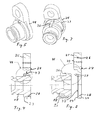
- connecting device 11 is used to connect a pipe 12, which is part of a complex fluid line, to another component or unit 13, which may be a fluid power device, such as an oil-lubricated bearing housing for a turbocharger in the motor vehicle.
- the connection device 11 includes a pipe end 14 of the fluid line and a connection region 15 of the component 13.
- the housing 16 of the unit 13 has a flow bore 17.
- a metallic, hollow cylindrical connecting piece 18 is inserted over a partial length, wherein the periphery of the connecting piece 18 is sealed by an O-shaped sealing ring 19 opposite the flow bore 17.
- the through hole 21 of the connecting piece 18 is formed step-shaped. In the outwardly directed, provided with a larger inner diameter step 22, the pipe end 14 is soldered frontally.
- the pipe end 14 with the connecting piece 18 is part of the pipe 12, which is a part of the complex, not completely shown here fluid line.
- the outer diameter of the hollow cylindrical connecting piece 18 is slightly smaller than the inner diameter of the flow bore 17, in which the connecting piece 18 is inserted.
- the connecting piece 18 is provided at its outer end with a radially outwardly directed annular flange 23.
- a deferred retaining plate 24th On the outside of the flow bore 17 lying circumference of the annular flange 23 is a deferred retaining plate 24th
- the holding plate 24 on the one hand a mounting portion 25 with a bolt hole 26 and on the other hand, a pipe receiving portion 27 with an axially parallel tube hole 28, which the connecting piece 18 in the assembled state ( 4 and 5 ).
- the fastening region 25 of the retaining plate 24 has a stop surface 29, which bears against the housing 16 and whose bolt hole 26 is aligned with a threaded bore 31 of the housing 16.
- the connection device 11 is fastened there to the housing 16 via an engaging screw bolt 32.
- the holding plate 24 has a smaller thickness in the tube receiving region 27 than in the attachment region 25.
- the tube receiving region 27 is provided with a surface 33 recessed relative to the stop surface 29.
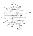
- the tube hole 28 penetrating this surface 33 forms circumferentially a circular ring 34, which corresponds to a circumferential recess 35 at the front end of the connecting piece 18 ( Fig. 2 ).
- the annular flange 23 is provided at the apex with an axial groove 36, the bottom 37 has an oblique ramp surface 38 at the beginning.
- the holding plate 24 has in its corresponding vertex of the tube hole 28 in the axial groove 36 mating latch 39.
- the detent 39 protrudes at the apex of the pipe receiving area forming first bore 28 in extension of a projecting from the apex of the bore 28 inwardly, axial web 40 (FIG. Fig. 8 ) from the surface 33 and has an oblique edge 41 on the front side.
- the type of feather key representing axial web 40 engages in the matching axial apex 36 in the connecting piece 18 a.
- the retaining plate 24 is pushed onto the connecting piece 18 before the fluid line is mounted, wherein the retaining plate 24 slides with its latching nose 39 into the axial groove 36 of the connecting piece 24 ( Fig. 3 ).
- the detent 39 slides on the inclined surface 38 up ( Fig. 2 ) and snaps behind the groove bottom 37 and is located at the there formed by a jump on the main diameter of the connecting piece 18 vertical annular surface 42 (FIG. Fig. 7 ) at.
- the holding plate 24 is secured on the connecting piece 18 against rotation and displacement by this positive connection ( Fig. 5 ).
- the holding plate 24 which may be made of plastic, serves to fix the fluid line, so that the connecting piece 18 can not slip out of the flow bore 17.
Landscapes
- Engineering & Computer Science (AREA)
- General Engineering & Computer Science (AREA)
- Mechanical Engineering (AREA)
- Quick-Acting Or Multi-Walled Pipe Joints (AREA)
Claims (4)
- Dispositif de connexion (11) pour relier une extrémité (14) d'une conduite fluidique (12) à un groupe (13) présentant un alésage de passage (17) et devant être alimenté en fluide, notamment d'un groupe d'un véhicule automobile,
comprenant une plaque de retenue (24) présentant deux alésages (26, 28) décalés latéralement l'un par rapport à l'autre, qui entoure l'extrémité (14) de la conduite fluidique (12) pouvant être enfoncée dans l'alésage de passage (17) dans un premier alésage (28), et qui peut être fixée au groupe (13) par le biais du deuxième alésage (26), comprenant une bride annulaire (23) orientée vers l'extérieur, disposée sur l'extrémité (14) de la conduite fluidique (12), qui forme une surface de pression annulaire contre laquelle s'applique la région de réception de tuyau (27) de la plaque de retenue (24), et
comprenant une tubulure de raccordement (18) connectée à l'extrémité (14) de la conduite fluidique (12), qui peut être enfoncée dans l'alésage de passage (17),
la plaque de retenue (24) pouvant être enfilée sur la tubulure de raccordement (18) de manière fixée par engagement par correspondance géométrique en rotation et en déplacement axial,
caractérisé en ce que
la plaque de retenue (24) présente, au sommet du premier alésage (28), un nez d'encliquetage saillant (39) qui se situe dans une rainure de sommet axiale (36) dans la tubulure de raccordement (18) et qui vient en prise dans un épaulement de verrouillage (42) dans le fond de rainure (37). - Dispositif (11) selon la revendication 1, caractérisé en ce que la connexion par engagement par correspondance géométrique de la tubulure de raccordement (18) et de la plaque de retenue (24) retient les deux pièces (18, 24) l'une par rapport à l'autre en position fixée en rotation et axialement.
- Dispositif (11) selon l'une quelconque des revendications 1 ou 2, caractérisé en ce que la plaque de retenue (24) présente, au sommet du premier alésage (28) formant la région de réception de tuyau, une nervure axiale saillant vers l'intérieur dans le sommet de l'alésage (28), laquelle vient en prise dans une rainure de sommet axiale (36) dans la tubulure de raccordement (18).
- Dispositif (11) selon la revendication 1, caractérisé en ce que la plaque de retenue (24) présente dans la région de fixation (25) une plus grande épaisseur que dans la région de réception de tuyau (27).
Applications Claiming Priority (1)
| Application Number | Priority Date | Filing Date | Title |
|---|---|---|---|
| DE102008055470A DE102008055470A1 (de) | 2008-12-02 | 2008-12-02 | Anschlussvorrichtung zur Befestigung und zum dichten Verbinden einer Fluidleitung mit einem anderen fluidführenden Bauteil |
Publications (2)
| Publication Number | Publication Date |
|---|---|
| EP2194307A1 EP2194307A1 (fr) | 2010-06-09 |
| EP2194307B1 true EP2194307B1 (fr) | 2012-10-10 |
Family
ID=41331461
Family Applications (1)
| Application Number | Title | Priority Date | Filing Date |
|---|---|---|---|
| EP20090174830 Active EP2194307B1 (fr) | 2008-12-02 | 2009-11-03 | Connexion étanche entre un tuyau et une autre pièce dans laquelle circule un fluide |
Country Status (2)
| Country | Link |
|---|---|
| EP (1) | EP2194307B1 (fr) |
| DE (1) | DE102008055470A1 (fr) |
Family Cites Families (7)
| Publication number | Priority date | Publication date | Assignee | Title |
|---|---|---|---|---|
| JPH0435246Y2 (fr) * | 1986-09-29 | 1992-08-20 | ||
| US5174612A (en) | 1991-07-15 | 1992-12-29 | Senior Engineering Investments, B.V. | Vibration isolating sealing clamp for conduit structures |
| FR2694797B1 (fr) | 1992-08-12 | 1994-11-04 | Hutchinson | Platine et embout pour dispositif de raccordement, dispositif de raccordement et son procédé de réalisation. |
| US6216761B1 (en) * | 1999-03-19 | 2001-04-17 | Linear Products, Inc. | Free turning chilling wheel assembly |
| US6318765B1 (en) * | 1999-10-29 | 2001-11-20 | Automotive Fluid Systems, Inc. | Serviceable mounting device for conduit |
| US6942255B2 (en) * | 2002-04-23 | 2005-09-13 | Q3Jmc, Inc. | Twist fitting for air tank connections |
| DE102004036719A1 (de) * | 2003-08-07 | 2005-03-17 | Denso Corp., Kariya | Rohrverbindungskonstruktion und Herstellungsverfahren dafür |
-
2008
- 2008-12-02 DE DE102008055470A patent/DE102008055470A1/de not_active Withdrawn
-
2009
- 2009-11-03 EP EP20090174830 patent/EP2194307B1/fr active Active
Also Published As
| Publication number | Publication date |
|---|---|
| EP2194307A1 (fr) | 2010-06-09 |
| DE102008055470A1 (de) | 2010-07-01 |
Similar Documents
| Publication | Publication Date | Title |
|---|---|---|
| DE102004032572B4 (de) | Verbindungsanordnung mit Kontaktstift | |
| DE29706377U1 (de) | Muffe für Verbundrohre oder Rohre aus Kunststoff | |
| EP2199652B1 (fr) | Dispositif de connexion étanche et de fixation d'une conduite de fluide dotée d'un autre composant conduisant du liquide | |
| EP3724470A1 (fr) | Dispositif et procédé de raccordement de composants de conduite de fluide, en particulier dans la ligne de gaz d'échappement d'un véhicule automobile | |
| EP3854618B1 (fr) | Réservoir de carburant comprenant un raccord | |
| DE202005002159U1 (de) | Kupplungseinrichtung | |
| DE102005044304A1 (de) | Anschlussanordnung zum Anschließen einer Rohrleitung an ein System | |
| DE19927431A1 (de) | Anschluß mit einem an einer Leitung stoffschlüssig befestigten Stecker | |
| EP2133615B1 (fr) | Dispositif de couplage, en particulier pour une installation d'air frais | |
| DE102013113813A1 (de) | Steckverbinder zum Anbinden einer medienführenden Fluidleitung eines Kraftfahrzeugs | |
| EP2194307B1 (fr) | Connexion étanche entre un tuyau et une autre pièce dans laquelle circule un fluide | |
| DE60306786T2 (de) | Schnellverbindung für einen mit gewinde versehener fluidbauteil | |
| DE202011107346U1 (de) | Anschlussfitting | |
| DE102007019332A1 (de) | Anschlusselement für Fluidleitungen sowie Druckfluid führendes Bauelement | |
| EP1484544B1 (fr) | Traversée de conduite pour l'installation d'un tube sanitaire à travers un mur | |
| EP1258624B1 (fr) | Système d'alimentation pour un moteur à combustion interne | |
| EP3894733A1 (fr) | Dispositif d'étanchéité, manchon d'étanchéité et leur utilisation | |
| DE102007007370A1 (de) | Verbindungsanordnung für Fluidleitungen | |
| DE20313792U1 (de) | Zugfeste Rohrverbindung | |
| DE102004024716B4 (de) | Lösbare Ladeluft-Kupplungsmuffe | |
| DE102014213729A1 (de) | Anschlussstutzen sowie Hochdruckpumpe mit Anschlussstutzen | |
| DE102021110130B4 (de) | Anschlussvorrichtung zum Anschluss einer Wasserpumpe an eine Ölpumpe einer Brennkraftmaschine und Verfahren zur Montage einer Wasserpumpe an einer Ölpumpe einer Brennkraftmaschine | |
| EP2910792A1 (fr) | Dispositif de liaison pour la liaison fluidique d'une section de tube de fluide avec une autre section de tube de fluide | |
| DE102007012536B4 (de) | Leitung mit Knickschutzhülse und Knickschutzhülse | |
| WO2019020230A1 (fr) | Élément de couplage flexible avec compensation de tolérances pour la connexion flexible de deux éléments conducteurs de fluides |
Legal Events
| Date | Code | Title | Description |
|---|---|---|---|
| PUAI | Public reference made under article 153(3) epc to a published international application that has entered the european phase |
Free format text: ORIGINAL CODE: 0009012 |
|
| AK | Designated contracting states |
Kind code of ref document: A1 Designated state(s): AT BE BG CH CY CZ DE DK EE ES FI FR GB GR HR HU IE IS IT LI LT LU LV MC MK MT NL NO PL PT RO SE SI SK SM TR |
|
| AX | Request for extension of the european patent |
Extension state: AL BA RS |
|
| 17P | Request for examination filed |
Effective date: 20101209 |
|
| 17Q | First examination report despatched |
Effective date: 20110208 |
|
| GRAP | Despatch of communication of intention to grant a patent |
Free format text: ORIGINAL CODE: EPIDOSNIGR1 |
|
| GRAS | Grant fee paid |
Free format text: ORIGINAL CODE: EPIDOSNIGR3 |
|
| GRAA | (expected) grant |
Free format text: ORIGINAL CODE: 0009210 |
|
| AK | Designated contracting states |
Kind code of ref document: B1 Designated state(s): AT BE BG CH CY CZ DE DK EE ES FI FR GB GR HR HU IE IS IT LI LT LU LV MC MK MT NL NO PL PT RO SE SI SK SM TR |
|
| REG | Reference to a national code |
Ref country code: GB Ref legal event code: FG4D Free format text: NOT ENGLISH |
|
| REG | Reference to a national code |
Ref country code: AT Ref legal event code: REF Ref document number: 579128 Country of ref document: AT Kind code of ref document: T Effective date: 20121015 Ref country code: CH Ref legal event code: EP |
|
| REG | Reference to a national code |
Ref country code: IE Ref legal event code: FG4D Free format text: LANGUAGE OF EP DOCUMENT: GERMAN |
|
| REG | Reference to a national code |
Ref country code: DE Ref legal event code: R096 Ref document number: 502009005023 Country of ref document: DE Effective date: 20121206 |
|
| PG25 | Lapsed in a contracting state [announced via postgrant information from national office to epo] |
Ref country code: SI Free format text: LAPSE BECAUSE OF FAILURE TO SUBMIT A TRANSLATION OF THE DESCRIPTION OR TO PAY THE FEE WITHIN THE PRESCRIBED TIME-LIMIT Effective date: 20121010 |
|
| REG | Reference to a national code |
Ref country code: NL Ref legal event code: VDEP Effective date: 20121010 |
|
| REG | Reference to a national code |
Ref country code: LT Ref legal event code: MG4D |
|
| PG25 | Lapsed in a contracting state [announced via postgrant information from national office to epo] |
Ref country code: ES Free format text: LAPSE BECAUSE OF FAILURE TO SUBMIT A TRANSLATION OF THE DESCRIPTION OR TO PAY THE FEE WITHIN THE PRESCRIBED TIME-LIMIT Effective date: 20130121 Ref country code: LT Free format text: LAPSE BECAUSE OF FAILURE TO SUBMIT A TRANSLATION OF THE DESCRIPTION OR TO PAY THE FEE WITHIN THE PRESCRIBED TIME-LIMIT Effective date: 20121010 Ref country code: SE Free format text: LAPSE BECAUSE OF FAILURE TO SUBMIT A TRANSLATION OF THE DESCRIPTION OR TO PAY THE FEE WITHIN THE PRESCRIBED TIME-LIMIT Effective date: 20121010 Ref country code: HR Free format text: LAPSE BECAUSE OF FAILURE TO SUBMIT A TRANSLATION OF THE DESCRIPTION OR TO PAY THE FEE WITHIN THE PRESCRIBED TIME-LIMIT Effective date: 20121010 Ref country code: NL Free format text: LAPSE BECAUSE OF FAILURE TO SUBMIT A TRANSLATION OF THE DESCRIPTION OR TO PAY THE FEE WITHIN THE PRESCRIBED TIME-LIMIT Effective date: 20121010 Ref country code: NO Free format text: LAPSE BECAUSE OF FAILURE TO SUBMIT A TRANSLATION OF THE DESCRIPTION OR TO PAY THE FEE WITHIN THE PRESCRIBED TIME-LIMIT Effective date: 20130110 Ref country code: IS Free format text: LAPSE BECAUSE OF FAILURE TO SUBMIT A TRANSLATION OF THE DESCRIPTION OR TO PAY THE FEE WITHIN THE PRESCRIBED TIME-LIMIT Effective date: 20130210 Ref country code: FI Free format text: LAPSE BECAUSE OF FAILURE TO SUBMIT A TRANSLATION OF THE DESCRIPTION OR TO PAY THE FEE WITHIN THE PRESCRIBED TIME-LIMIT Effective date: 20121010 |
|
| BERE | Be: lapsed |
Owner name: CONTITECH TECHNO-CHEMIE G.M.B.H. Effective date: 20121130 |
|
| PG25 | Lapsed in a contracting state [announced via postgrant information from national office to epo] |
Ref country code: PT Free format text: LAPSE BECAUSE OF FAILURE TO SUBMIT A TRANSLATION OF THE DESCRIPTION OR TO PAY THE FEE WITHIN THE PRESCRIBED TIME-LIMIT Effective date: 20130211 Ref country code: PL Free format text: LAPSE BECAUSE OF FAILURE TO SUBMIT A TRANSLATION OF THE DESCRIPTION OR TO PAY THE FEE WITHIN THE PRESCRIBED TIME-LIMIT Effective date: 20121010 Ref country code: GR Free format text: LAPSE BECAUSE OF FAILURE TO SUBMIT A TRANSLATION OF THE DESCRIPTION OR TO PAY THE FEE WITHIN THE PRESCRIBED TIME-LIMIT Effective date: 20130111 Ref country code: LV Free format text: LAPSE BECAUSE OF FAILURE TO SUBMIT A TRANSLATION OF THE DESCRIPTION OR TO PAY THE FEE WITHIN THE PRESCRIBED TIME-LIMIT Effective date: 20121010 |
|
| PG25 | Lapsed in a contracting state [announced via postgrant information from national office to epo] |
Ref country code: EE Free format text: LAPSE BECAUSE OF FAILURE TO SUBMIT A TRANSLATION OF THE DESCRIPTION OR TO PAY THE FEE WITHIN THE PRESCRIBED TIME-LIMIT Effective date: 20121010 Ref country code: CZ Free format text: LAPSE BECAUSE OF FAILURE TO SUBMIT A TRANSLATION OF THE DESCRIPTION OR TO PAY THE FEE WITHIN THE PRESCRIBED TIME-LIMIT Effective date: 20121010 Ref country code: BG Free format text: LAPSE BECAUSE OF FAILURE TO SUBMIT A TRANSLATION OF THE DESCRIPTION OR TO PAY THE FEE WITHIN THE PRESCRIBED TIME-LIMIT Effective date: 20130110 Ref country code: SK Free format text: LAPSE BECAUSE OF FAILURE TO SUBMIT A TRANSLATION OF THE DESCRIPTION OR TO PAY THE FEE WITHIN THE PRESCRIBED TIME-LIMIT Effective date: 20121010 Ref country code: DK Free format text: LAPSE BECAUSE OF FAILURE TO SUBMIT A TRANSLATION OF THE DESCRIPTION OR TO PAY THE FEE WITHIN THE PRESCRIBED TIME-LIMIT Effective date: 20121010 |
|
| REG | Reference to a national code |
Ref country code: IE Ref legal event code: MM4A |
|
| PLBE | No opposition filed within time limit |
Free format text: ORIGINAL CODE: 0009261 |
|
| STAA | Information on the status of an ep patent application or granted ep patent |
Free format text: STATUS: NO OPPOSITION FILED WITHIN TIME LIMIT |
|
| PG25 | Lapsed in a contracting state [announced via postgrant information from national office to epo] |
Ref country code: RO Free format text: LAPSE BECAUSE OF FAILURE TO SUBMIT A TRANSLATION OF THE DESCRIPTION OR TO PAY THE FEE WITHIN THE PRESCRIBED TIME-LIMIT Effective date: 20121010 Ref country code: BE Free format text: LAPSE BECAUSE OF NON-PAYMENT OF DUE FEES Effective date: 20121130 |
|
| 26N | No opposition filed |
Effective date: 20130711 |
|
| PG25 | Lapsed in a contracting state [announced via postgrant information from national office to epo] |
Ref country code: IE Free format text: LAPSE BECAUSE OF NON-PAYMENT OF DUE FEES Effective date: 20121103 |
|
| REG | Reference to a national code |
Ref country code: DE Ref legal event code: R097 Ref document number: 502009005023 Country of ref document: DE Effective date: 20130711 |
|
| PG25 | Lapsed in a contracting state [announced via postgrant information from national office to epo] |
Ref country code: MT Free format text: LAPSE BECAUSE OF FAILURE TO SUBMIT A TRANSLATION OF THE DESCRIPTION OR TO PAY THE FEE WITHIN THE PRESCRIBED TIME-LIMIT Effective date: 20121010 Ref country code: CY Free format text: LAPSE BECAUSE OF FAILURE TO SUBMIT A TRANSLATION OF THE DESCRIPTION OR TO PAY THE FEE WITHIN THE PRESCRIBED TIME-LIMIT Effective date: 20121010 |
|
| PG25 | Lapsed in a contracting state [announced via postgrant information from national office to epo] |
Ref country code: TR Free format text: LAPSE BECAUSE OF FAILURE TO SUBMIT A TRANSLATION OF THE DESCRIPTION OR TO PAY THE FEE WITHIN THE PRESCRIBED TIME-LIMIT Effective date: 20121010 Ref country code: MC Free format text: LAPSE BECAUSE OF NON-PAYMENT OF DUE FEES Effective date: 20121130 |
|
| PG25 | Lapsed in a contracting state [announced via postgrant information from national office to epo] |
Ref country code: SM Free format text: LAPSE BECAUSE OF FAILURE TO SUBMIT A TRANSLATION OF THE DESCRIPTION OR TO PAY THE FEE WITHIN THE PRESCRIBED TIME-LIMIT Effective date: 20121010 Ref country code: LU Free format text: LAPSE BECAUSE OF NON-PAYMENT OF DUE FEES Effective date: 20121103 |
|
| REG | Reference to a national code |
Ref country code: CH Ref legal event code: PL |
|
| PG25 | Lapsed in a contracting state [announced via postgrant information from national office to epo] |
Ref country code: LI Free format text: LAPSE BECAUSE OF NON-PAYMENT OF DUE FEES Effective date: 20131130 Ref country code: CH Free format text: LAPSE BECAUSE OF NON-PAYMENT OF DUE FEES Effective date: 20131130 Ref country code: HU Free format text: LAPSE BECAUSE OF FAILURE TO SUBMIT A TRANSLATION OF THE DESCRIPTION OR TO PAY THE FEE WITHIN THE PRESCRIBED TIME-LIMIT Effective date: 20091103 |
|
| PG25 | Lapsed in a contracting state [announced via postgrant information from national office to epo] |
Ref country code: MK Free format text: LAPSE BECAUSE OF FAILURE TO SUBMIT A TRANSLATION OF THE DESCRIPTION OR TO PAY THE FEE WITHIN THE PRESCRIBED TIME-LIMIT Effective date: 20121010 |
|
| REG | Reference to a national code |
Ref country code: FR Ref legal event code: PLFP Year of fee payment: 7 |
|
| REG | Reference to a national code |
Ref country code: AT Ref legal event code: MM01 Ref document number: 579128 Country of ref document: AT Kind code of ref document: T Effective date: 20141103 |
|
| PG25 | Lapsed in a contracting state [announced via postgrant information from national office to epo] |
Ref country code: AT Free format text: LAPSE BECAUSE OF NON-PAYMENT OF DUE FEES Effective date: 20141103 |
|
| REG | Reference to a national code |
Ref country code: FR Ref legal event code: PLFP Year of fee payment: 8 |
|
| REG | Reference to a national code |
Ref country code: FR Ref legal event code: PLFP Year of fee payment: 9 |
|
| REG | Reference to a national code |
Ref country code: DE Ref legal event code: R084 Ref document number: 502009005023 Country of ref document: DE |
|
| PGFP | Annual fee paid to national office [announced via postgrant information from national office to epo] |
Ref country code: DE Payment date: 20251130 Year of fee payment: 17 |
|
| PGFP | Annual fee paid to national office [announced via postgrant information from national office to epo] |
Ref country code: GB Payment date: 20251121 Year of fee payment: 17 |
|
| PGFP | Annual fee paid to national office [announced via postgrant information from national office to epo] |
Ref country code: IT Payment date: 20251125 Year of fee payment: 17 |
|
| PGFP | Annual fee paid to national office [announced via postgrant information from national office to epo] |
Ref country code: FR Payment date: 20251121 Year of fee payment: 17 |