EP2194324A2 - Dispositif de crémation intégré mobile - Google Patents
Dispositif de crémation intégré mobile Download PDFInfo
- Publication number
- EP2194324A2 EP2194324A2 EP09011921A EP09011921A EP2194324A2 EP 2194324 A2 EP2194324 A2 EP 2194324A2 EP 09011921 A EP09011921 A EP 09011921A EP 09011921 A EP09011921 A EP 09011921A EP 2194324 A2 EP2194324 A2 EP 2194324A2
- Authority
- EP
- European Patent Office
- Prior art keywords
- waste heat
- incinerator
- cooling unit
- corpse
- air
- Prior art date
- Legal status (The legal status is an assumption and is not a legal conclusion. Google has not performed a legal analysis and makes no representation as to the accuracy of the status listed.)
- Withdrawn
Links
Images



Classifications
-
- F—MECHANICAL ENGINEERING; LIGHTING; HEATING; WEAPONS; BLASTING
- F23—COMBUSTION APPARATUS; COMBUSTION PROCESSES
- F23G—CREMATION FURNACES; CONSUMING WASTE PRODUCTS BY COMBUSTION
- F23G1/00—Furnaces for cremation of human or animal carcasses
-
- F—MECHANICAL ENGINEERING; LIGHTING; HEATING; WEAPONS; BLASTING
- F23—COMBUSTION APPARATUS; COMBUSTION PROCESSES
- F23G—CREMATION FURNACES; CONSUMING WASTE PRODUCTS BY COMBUSTION
- F23G5/00—Incineration of waste; Incinerator constructions; Details, accessories or control therefor
- F23G5/40—Portable or mobile incinerators
-
- F—MECHANICAL ENGINEERING; LIGHTING; HEATING; WEAPONS; BLASTING
- F23—COMBUSTION APPARATUS; COMBUSTION PROCESSES
- F23G—CREMATION FURNACES; CONSUMING WASTE PRODUCTS BY COMBUSTION
- F23G5/00—Incineration of waste; Incinerator constructions; Details, accessories or control therefor
- F23G5/44—Details; Accessories
- F23G5/46—Recuperation of heat
-
- F—MECHANICAL ENGINEERING; LIGHTING; HEATING; WEAPONS; BLASTING
- F23—COMBUSTION APPARATUS; COMBUSTION PROCESSES
- F23G—CREMATION FURNACES; CONSUMING WASTE PRODUCTS BY COMBUSTION
- F23G2203/00—Furnace arrangements
- F23G2203/60—Mobile furnace
- F23G2203/601—Mobile furnace carried by a vehicle
-
- Y—GENERAL TAGGING OF NEW TECHNOLOGICAL DEVELOPMENTS; GENERAL TAGGING OF CROSS-SECTIONAL TECHNOLOGIES SPANNING OVER SEVERAL SECTIONS OF THE IPC; TECHNICAL SUBJECTS COVERED BY FORMER USPC CROSS-REFERENCE ART COLLECTIONS [XRACs] AND DIGESTS
- Y02—TECHNOLOGIES OR APPLICATIONS FOR MITIGATION OR ADAPTATION AGAINST CLIMATE CHANGE
- Y02E—REDUCTION OF GREENHOUSE GAS [GHG] EMISSIONS, RELATED TO ENERGY GENERATION, TRANSMISSION OR DISTRIBUTION
- Y02E20/00—Combustion technologies with mitigation potential
- Y02E20/12—Heat utilisation in combustion or incineration of waste
Definitions
- the present invention relates generally to a cremation device for cremating a corpse and, more particularly, to a movable integrated cremation device, which can be towed using a vehicle, cools waste heat of high temperature generated during cremation, and eliminates dust and offensive odors from the waste heat, prior to discharging the waste heat to the outside.
- a corpse needs to be transferred to a designated crematorium to be cremated.
- the movement of the corpse is inevitably limited so as to prevent the epidemic from spreading.
- an object of the present invention is to provide a movable integrated cremation device, which can be relocated to the location of a corpse and obviates the necessity of directly installing a simple cremation device at the spot where the corpse is located, thus making it convenient to cremate the corpse and preventing environmental pollution resulting from waste heat, dust and offensive odors which are generated during cremation of the corpse.
- the present invention provides a movable integrated cremation device having at least one trailer which can be towed and relocated, an incinerator for burning a corpse, a cooling unit for cooling waste heat emitted from the incinerator, a dust collector for eliminating dust and offensive odors from the waste heat which is discharged, a waste heat discharge unit for discharging waste heat from which the dust and the offensive odors have been removed, a gas supply unit for supplying fuel required for combustion to the incinerator, and an electricity supply unit for supplying electricity used to operate the components.
- the trailer may be provided with a lift for pulling a corpse to the mouth of the incinerator.
- the cremation device may include two or more trailers. Furthermore, in the state of the above-mentioned components being separately mounted on corresponding trailers, the trailers are connected to each other before being operated.
- the incinerator may include at least one burner for burning a corpse, and a first blower for supplying combustion air during cremation.
- the cooling unit may include an air-cooling unit which primarily cools waste heat generated from the incinerator, and a water-cooling unit which secondarily cools the waste heat cooled by the air-cooling unit.
- the air-cooling unit may be provided with a second blower which supplies cold air to perform a heat exchange process.
- the water-cooling unit may be provided with a water tank for storing water therein, and a pump for feeding water from the water tank to the water-cooling unit.
- the dust collector may include a pulse dust collector for eliminating dust from the waste heat, and an electric dust collector for eliminating offensive odors from the waste heat.
- the waste heat discharge unit may include a chimney for discharging the waste heat, a third blower for forcibly discharging the waste heat through the chimney, and a muffler which is installed to an outlet side of the third blower so as to decrease noise.
- the movable integrated cremation device according to the present invention is advantageous in that respective components are mounted on movable trailers, so that the device can be rapidly towed using a general access road to a spot where a corpse is located, thus allowing the corpse to be easily handled.
- the movable integrated cremation device according to the present invention is advantageous in that waste heat generated during the cremation of a corpse is cooled and thereafter dust and offensive odors are eliminated from the waste heat before it is discharged, thus preventing the surrounding environment from being contaminated, in addition to enabling the safe use of the device.
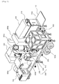
- FIG. 1 is a perspective view illustrating a movable cremation device according to the present invention
- FIG. 2 is a plan view illustrating the movable cremation device according to the present invention
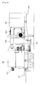
- FIG. 3 is a left side view illustrating the movable cremation device according to the present invention.
- FIG. 4 is a right side view illustrating the movable cremation device according to the present invention
- FIG. 5 is a view illustrating the operation of the lift of the movable cremation device according to the present invention.
- the movable cremation device of the present invention includes trailers 100a and 100b which may be towed to a new location, an incinerator 200 which burns a corpse, cooling units 300a and 300b which cool waste heat emitted from the incinerator 200, dust collectors 400a and 400b which eliminate dust and offensive odors from the emitted waste heat, a waste heat discharge unit 500 which discharges the waste heat after the dust and offensive odors have been eliminated from the waste heat, a gas supply unit 600 which supplies fuel required for combustion in the incinerator 200, and an electricity supply unit 700 which supplies electricity used to operate the above components.
- the trailers 100a and 100b may be connected to a towing vehicle such as a truck or a combine so as to be towed, and may stop independently when the trailers 100a and 100b are disconnected from the towing vehicle.
- the trailers 100a and 100b allow the cremation components mounted thereon to be conveniently transferred and set up.
- the trailers 100a and 100b are provided with a lift 110 for pulling a corpse to a mouth of the incinerator 200.
- the lift 110 is constructed so that it is folded when the device is moved and is unfolded when the device is being used.
- the device is provided with two or more trailers to allow the components to be separately mounted on the trailers 100a and 100b.
- the components are connected to each other to be operated.
- the lift 110 may be installed to only the trailer 100a having the incinerator 200.
- the incinerator 200 functions to burn a corpse. As shown in the drawings, the incinerator 200 is provided with at least one burner 210 for burning a corpse and a first blower 220 for supplying combustion air during incineration.
- the incinerator 200 is heated until its internal temperature exceeds 850°C.
- the inner surface of the incinerator 200 is finished using an insulating material and firebrick so as to protect the incinerator 200 and prevent heat from being radiated to the outside.
- each cooling unit 300a or 300b functions to cool waste heat of high temperature, which is discharged after a corpse is incinerated by the incinerator 200.
- Each cooling unit 300a or 300b is constructed to reduce the temperature of the waste heat from 850°C or more to 200°C or less.
- the cooling units 300a and 300b preferably include an air-cooling unit 300a and a water-cooling unit 300b so as to smoothly perform the cooling operation in stages.
- the air-cooling unit 300a primarily cools waste heat generated from the incinerator 200 to a temperature of 600°C or less.
- the water-cooling unit 300b secondarily cools waste heat cooled by the air-cooling unit 300a to a temperature of 200°C or less.
- the air-cooling unit 300a reduces the load put on the water-cooling unit 300b, thus ensuring reliable operation.
- the air-cooling unit 300a is provided with a second blower 310 which supplies cold air to perform a heat exchange process.
- the water-cooling unit 300b is provided with a water tank 320 which stores water therein, and a pump 330 which feeds water from the water tank 320 to the water-cooling unit 300b.
- the water tank 320 of the water-cooling unit 300b is constructed to store at least 8 tons of water, thus ensuring the smooth supply of cooling water.
- one end of the first blower 220 is connected to the incinerator 200, while the other end is connected to the air-cooling unit 300a, thus supplying hot air, which goes through a heat exchange process in the air-cooling unit 300a, to the incinerator 200 to serve as combustion air.
- the incinerator 200 is heated so that its internal temperature exceeds 850°C. If external cold air is fed into the incinerator 200, more burners are required to burn a corpse.
- the dust collectors 400a and 400b function to eliminate dust and offensive odors from waste heat which is discharged from the cooling units 300a and 300b.
- the dust collectors 400a and 400b include a pulse dust collector 400a for primarily eliminating dust from the waste heat, and an electric dust collector 400b for secondarily eliminating offensive odors from the waste heat, thus eliminating the dust and odors in stages.
- the pulse dust collector 400a forces the introduced waste heat to pass through a bag filter, whereby the bag filter captures dust.
- the dust is shaken away from the bag filter by pulses of air pressure. Thereby, the pulse dust collector 400a can be used for a lengthy period of time.
- the electric dust collector 400b When air is poorly ventilated because of it being a rainy season or low atmospheric pressure, the electric dust collector 400b eliminates peculiar odors generated from the cremation device.
- the electric dust collector 400b passes waste heat between metallic plates around which a magnetic field is formed, thus collecting fine dust and odor particles, which have passed through the bag filter, using electric force, and then getting rid of the fine dust and odor particles.
- the waste heat discharge unit 500 serves to discharge waste heat from which dust and offensive odors were eliminated by passing the waste heat through the dust collectors 400a and 400b.
- the waste heat discharge unit 500 includes a chimney 510, a third blower 520 for forcibly discharging waste heat through the chimney 510, and a muffler 530 which is installed to the outlet side of the third blower 520 to decrease noise.
- the gas supply unit 600 functions to supply fuel required for combustion to the incinerator 200.
- the gas supply unit 600 is usually connected to a gas tank.
- a vaporizer having the capacity of 100kg or more and a pressure regulator of 100kg or more are connected to the gas supply unit 600, thus allowing gas to be reliably supplied.
- the electricity supply unit 700 functions to supply electricity which is used for operation of the incinerator 200, the cooling units 300a and 300b, the dust collectors 400a and 400b, and the waste heat discharge unit 500, and is constructed to have the power generating capacity of 50Kw or more.
- the incinerator 200, the cooling units 300a and 300b and the gas supply unit 600 are provided on one trailer 100a equipped with the lift 110, while the water tank 320, the waste heat discharge unit 500, the dust collectors 400a and 400b and the electricity supply unit 700 are provided on the other trailer 100b.
- the trailers 100a and 100b on which the associated components are loaded are moved to the location of a corpse, are stopped side by side, and are connected to each other to be operated.
- the present invention provides a movable integrated cremation device, in which respective components are loaded on corresponding movable trailers, thus allowing the device to be rapidly towed using general access roads to the location of a corpse, therefore making it easier to handle the corpse, and in which waste heat generated during the cremation of a corpse is cooled and then dust and offensive odors are eliminated from the waste heat before it is discharged, thus preventing the ambient environment from being contaminated, and enabling the safe use of the device.
Landscapes
- Engineering & Computer Science (AREA)
- Mechanical Engineering (AREA)
- General Engineering & Computer Science (AREA)
- Air Supply (AREA)
Applications Claiming Priority (2)
| Application Number | Priority Date | Filing Date | Title |
|---|---|---|---|
| KR1020080122980A KR100892037B1 (ko) | 2008-12-05 | 2008-12-05 | 이동식 일체형 화장 설비 |
| KR1020090017195A KR100892034B1 (ko) | 2009-02-27 | 2009-02-27 | 이동식 일체형 화장 설비 |
Publications (2)
| Publication Number | Publication Date |
|---|---|
| EP2194324A2 true EP2194324A2 (fr) | 2010-06-09 |
| EP2194324A3 EP2194324A3 (fr) | 2014-03-05 |
Family
ID=41820205
Family Applications (1)
| Application Number | Title | Priority Date | Filing Date |
|---|---|---|---|
| EP09011921.5A Withdrawn EP2194324A3 (fr) | 2008-12-05 | 2009-09-18 | Dispositif de crémation intégré mobile |
Country Status (4)
| Country | Link |
|---|---|
| US (1) | US20100139533A1 (fr) |
| EP (1) | EP2194324A3 (fr) |
| JP (1) | JP2010133693A (fr) |
| CN (1) | CN101749712A (fr) |
Cited By (3)
| Publication number | Priority date | Publication date | Assignee | Title |
|---|---|---|---|---|
| CN104633664A (zh) * | 2015-02-08 | 2015-05-20 | 湖南祥润环保机械制造有限公司 | 固定式病死畜禽动物尸体无害化处理设备 |
| WO2017068312A1 (fr) * | 2015-10-23 | 2017-04-27 | Inciner8 Ltd | Crématoriums |
| EP3395771A1 (fr) * | 2017-04-28 | 2018-10-31 | F.M.I. Process S.A. | Installation compacte pour l'incineration de boues |
Families Citing this family (10)
| Publication number | Priority date | Publication date | Assignee | Title |
|---|---|---|---|---|
| CN102635864B (zh) * | 2012-05-08 | 2014-04-30 | 上海欣润环保设备有限公司 | 一种移动式环保火化炉 |
| US9822972B2 (en) | 2012-12-03 | 2017-11-21 | Tokyo Hakuzen Co., Ltd. | Cremation system |
| CN104197332A (zh) * | 2014-08-05 | 2014-12-10 | 湖南山河美生物环保科技股份有限公司 | 移动式病死畜禽动物尸体无害化处理设备 |
| US10767859B2 (en) * | 2014-08-19 | 2020-09-08 | Adler Hot Oil Service, LLC | Wellhead gas heater |
| CN104633665A (zh) * | 2015-02-08 | 2015-05-20 | 湖南祥润环保机械制造有限公司 | 车载式病死畜禽动物尸体无害化处理设备 |
| CN104633663A (zh) * | 2015-02-08 | 2015-05-20 | 湖南祥润环保机械制造有限公司 | 车载式病死畜禽动物尸体无害化处理设备专用焚烧炉 |
| JP6206572B2 (ja) * | 2016-10-24 | 2017-10-04 | 三浦工業株式会社 | ボイラ装置及びコジェネシステム |
| CN107940469A (zh) * | 2017-11-17 | 2018-04-20 | 环境保护部华南环境科学研究所 | 一种移动式垃圾处理及烟气净化集成装置及处理方法 |
| CN110631018B (zh) * | 2019-10-29 | 2025-05-02 | 生态环境部固体废物与化学品管理技术中心 | 一种用于畜禽尸体无害化处理的设备 |
| CN110578921A (zh) * | 2019-10-29 | 2019-12-17 | 生态环境部固体废物与化学品管理技术中心 | 一种用于焚烧畜禽尸体的设备 |
Family Cites Families (18)
| Publication number | Priority date | Publication date | Assignee | Title |
|---|---|---|---|---|
| JPS54129768A (en) * | 1978-03-30 | 1979-10-08 | Hiroe Takahashi | Moving cremation car |
| ATE49469T1 (de) * | 1981-04-09 | 1990-01-15 | Heat Exchanger Ind Inc | Verfahren zur herstellung eines waermeaustauschers und waermeaustauscher gemaess diesem verfahren. |
| JPS61132675A (ja) * | 1984-12-03 | 1986-06-20 | 三菱レイヨン株式会社 | 炭素繊維の表面処理方法 |
| JPH064185Y2 (ja) * | 1986-07-30 | 1994-02-02 | 勝久 増田 | ペット類火葬車 |
| JPH0729379Y2 (ja) * | 1988-04-08 | 1995-07-05 | 実 藤森 | 車載焼却炉 |
| JPH06159639A (ja) * | 1992-11-30 | 1994-06-07 | Kobe Steel Ltd | 灰の溶融装置 |
| DE19628741C2 (de) * | 1996-07-17 | 1999-11-04 | Sbw Sonderabfallentsorgung Bad | Verfahren zur Feuerbestattung |
| DE19652967C1 (de) * | 1996-12-19 | 1998-04-09 | Sbw Sonderabfallentsorgung Bad | Feuerbestattungseinrichtung |
| ES2160460B1 (es) * | 1998-10-01 | 2002-06-01 | Caronte Servicios Funerarios S | Sistema de incineracion transportable. |
| JP2001324115A (ja) * | 2000-05-16 | 2001-11-22 | Shidan Yo | 移動式遺体焼却装置 |
| GB2362326B (en) * | 2000-05-16 | 2002-06-05 | Yang Tzung Tai | Mobile cremating equipment |
| JP2002168416A (ja) * | 2000-12-04 | 2002-06-14 | O Saamu:Kk | 愛玩動物用火葬車 |
| JP3680755B2 (ja) * | 2001-04-09 | 2005-08-10 | Jfeエンジニアリング株式会社 | ダイオキシン汚染物の現地処理装置 |
| US6729247B2 (en) * | 2001-12-04 | 2004-05-04 | Andrew Brown | Mobile crematorium |
| JP4961156B2 (ja) * | 2006-03-28 | 2012-06-27 | メタウォーター株式会社 | 廃棄物の焼却廃熱の有効利用方法 |
| CN101084856A (zh) * | 2006-06-05 | 2007-12-12 | 丁云波 | 活动式殡仪馆 |
| KR100824597B1 (ko) * | 2006-11-29 | 2008-04-23 | 성래경 | 이동식 무취 친환경 화장로 장치 |
| ITBS20070143A1 (it) * | 2007-10-02 | 2009-04-03 | Cesarina Alessandretti | Cellula funeraria |
-
2009
- 2009-07-07 US US12/498,594 patent/US20100139533A1/en not_active Abandoned
- 2009-07-08 JP JP2009161584A patent/JP2010133693A/ja active Pending
- 2009-07-09 CN CN200910140329.7A patent/CN101749712A/zh active Pending
- 2009-09-18 EP EP09011921.5A patent/EP2194324A3/fr not_active Withdrawn
Cited By (3)
| Publication number | Priority date | Publication date | Assignee | Title |
|---|---|---|---|---|
| CN104633664A (zh) * | 2015-02-08 | 2015-05-20 | 湖南祥润环保机械制造有限公司 | 固定式病死畜禽动物尸体无害化处理设备 |
| WO2017068312A1 (fr) * | 2015-10-23 | 2017-04-27 | Inciner8 Ltd | Crématoriums |
| EP3395771A1 (fr) * | 2017-04-28 | 2018-10-31 | F.M.I. Process S.A. | Installation compacte pour l'incineration de boues |
Also Published As
| Publication number | Publication date |
|---|---|
| CN101749712A (zh) | 2010-06-23 |
| JP2010133693A (ja) | 2010-06-17 |
| US20100139533A1 (en) | 2010-06-10 |
| EP2194324A3 (fr) | 2014-03-05 |
Similar Documents
| Publication | Publication Date | Title |
|---|---|---|
| EP2194324A2 (fr) | Dispositif de crémation intégré mobile | |
| KR100892034B1 (ko) | 이동식 일체형 화장 설비 | |
| US5743196A (en) | Mobile waste incinerator | |
| KR102605034B1 (ko) | 마이크로 칩을 탑재한 식물 식재용 화분과 차량을 이용한 이동형 반려동물 화장장치 | |
| CN210861104U (zh) | 一种用于焚烧畜禽尸体的设备 | |
| JP3811890B2 (ja) | 車両搭載移動式一般雑芥焼却装置 | |
| KR100892037B1 (ko) | 이동식 일체형 화장 설비 | |
| JP2005024211A (ja) | 廃棄物ガス化燃焼システム | |
| KR100892038B1 (ko) | 이동식 화장 설비용 소각로 | |
| KR100892035B1 (ko) | 이동식 화장 설비용 소각로 | |
| CN210861105U (zh) | 一种用于畜禽尸体无害化处理的设备 | |
| JPH0729379Y2 (ja) | 車載焼却炉 | |
| JPH11304117A (ja) | 愛玩動物の遺体などを焼却するのに適した焼却炉及び焼却方法 | |
| JP3228408U (ja) | 車載用ペット遺体焼却装置 | |
| JP3216857U (ja) | 焼却炉システム | |
| JP4376213B2 (ja) | 愛玩動物用火葬車 | |
| CN213872697U (zh) | 一种环保型实验动物尸体无害化处理设备 | |
| CN216047721U (zh) | 一种医疗废弃物焚化车 | |
| JP3052293U (ja) | 燃焼炉 | |
| JPS5849456Y2 (ja) | 火葬炉 | |
| CN214094511U (zh) | 一种热能回收的固体废弃物焚烧炉 | |
| JPH0539295Y2 (fr) | ||
| RU2640623C2 (ru) | Передвижная установка для утилизации опасных медицинских и биологических отходов | |
| JP3749293B2 (ja) | 火葬炉 | |
| JP3036799U (ja) | 移動式廃棄物焼却車 |
Legal Events
| Date | Code | Title | Description |
|---|---|---|---|
| PUAI | Public reference made under article 153(3) epc to a published international application that has entered the european phase |
Free format text: ORIGINAL CODE: 0009012 |
|
| AK | Designated contracting states |
Kind code of ref document: A2 Designated state(s): AT BE BG CH CY CZ DE DK EE ES FI FR GB GR HR HU IE IS IT LI LT LU LV MC MK MT NL NO PL PT RO SE SI SK SM TR |
|
| AX | Request for extension of the european patent |
Extension state: AL BA RS |
|
| PUAL | Search report despatched |
Free format text: ORIGINAL CODE: 0009013 |
|
| AK | Designated contracting states |
Kind code of ref document: A3 Designated state(s): AT BE BG CH CY CZ DE DK EE ES FI FR GB GR HR HU IE IS IT LI LT LU LV MC MK MT NL NO PL PT RO SE SI SK SM TR |
|
| AX | Request for extension of the european patent |
Extension state: AL BA RS |
|
| RIC1 | Information provided on ipc code assigned before grant |
Ipc: F23G 1/00 20060101AFI20140129BHEP Ipc: F23G 5/40 20060101ALI20140129BHEP Ipc: F23G 5/46 20060101ALI20140129BHEP |
|
| STAA | Information on the status of an ep patent application or granted ep patent |
Free format text: STATUS: THE APPLICATION IS DEEMED TO BE WITHDRAWN |
|
| 18D | Application deemed to be withdrawn |
Effective date: 20140401 |