EP2194326A1 - Mit einem Kocher nutzbarer Heizung, Verfahren zur Herstellung davon und Kocher - Google Patents
Mit einem Kocher nutzbarer Heizung, Verfahren zur Herstellung davon und Kocher Download PDFInfo
- Publication number
- EP2194326A1 EP2194326A1 EP09169102A EP09169102A EP2194326A1 EP 2194326 A1 EP2194326 A1 EP 2194326A1 EP 09169102 A EP09169102 A EP 09169102A EP 09169102 A EP09169102 A EP 09169102A EP 2194326 A1 EP2194326 A1 EP 2194326A1
- Authority
- EP
- European Patent Office
- Prior art keywords
- heater
- heat
- heater body
- quartz tube
- cooker
- Prior art date
- Legal status (The legal status is an assumption and is not a legal conclusion. Google has not performed a legal analysis and makes no representation as to the accuracy of the status listed.)
- Withdrawn
Links
Images

Classifications
-
- H—ELECTRICITY
- H05—ELECTRIC TECHNIQUES NOT OTHERWISE PROVIDED FOR
- H05B—ELECTRIC HEATING; ELECTRIC LIGHT SOURCES NOT OTHERWISE PROVIDED FOR; CIRCUIT ARRANGEMENTS FOR ELECTRIC LIGHT SOURCES, IN GENERAL
- H05B6/00—Heating by electric, magnetic or electromagnetic fields
- H05B6/64—Heating using microwaves
- H05B6/80—Apparatus for specific applications
-
- F—MECHANICAL ENGINEERING; LIGHTING; HEATING; WEAPONS; BLASTING
- F24—HEATING; RANGES; VENTILATING
- F24C—DOMESTIC STOVES OR RANGES ; DETAILS OF DOMESTIC STOVES OR RANGES, OF GENERAL APPLICATION
- F24C7/00—Stoves or ranges heated by electric energy
- F24C7/04—Stoves or ranges heated by electric energy with heat radiated directly from the heating element
- F24C7/046—Ranges
-
- F—MECHANICAL ENGINEERING; LIGHTING; HEATING; WEAPONS; BLASTING
- F24—HEATING; RANGES; VENTILATING
- F24C—DOMESTIC STOVES OR RANGES ; DETAILS OF DOMESTIC STOVES OR RANGES, OF GENERAL APPLICATION
- F24C7/00—Stoves or ranges heated by electric energy
- F24C7/02—Stoves or ranges heated by electric energy using microwaves
-
- H—ELECTRICITY
- H05—ELECTRIC TECHNIQUES NOT OTHERWISE PROVIDED FOR
- H05B—ELECTRIC HEATING; ELECTRIC LIGHT SOURCES NOT OTHERWISE PROVIDED FOR; CIRCUIT ARRANGEMENTS FOR ELECTRIC LIGHT SOURCES, IN GENERAL
- H05B3/00—Ohmic-resistance heating
- H05B3/40—Heating elements having the shape of rods or tubes
- H05B3/42—Heating elements having the shape of rods or tubes non-flexible
- H05B3/48—Heating elements having the shape of rods or tubes non-flexible heating conductor embedded in insulating material
-
- F—MECHANICAL ENGINEERING; LIGHTING; HEATING; WEAPONS; BLASTING
- F24—HEATING; RANGES; VENTILATING
- F24C—DOMESTIC STOVES OR RANGES ; DETAILS OF DOMESTIC STOVES OR RANGES, OF GENERAL APPLICATION
- F24C15/00—Details
- F24C15/32—Arrangements of ducts for hot gases, e.g. in or around baking ovens
- F24C15/322—Arrangements of ducts for hot gases, e.g. in or around baking ovens with forced circulation
- F24C15/325—Arrangements of ducts for hot gases, e.g. in or around baking ovens with forced circulation electrically-heated
-
- Y—GENERAL TAGGING OF NEW TECHNOLOGICAL DEVELOPMENTS; GENERAL TAGGING OF CROSS-SECTIONAL TECHNOLOGIES SPANNING OVER SEVERAL SECTIONS OF THE IPC; TECHNICAL SUBJECTS COVERED BY FORMER USPC CROSS-REFERENCE ART COLLECTIONS [XRACs] AND DIGESTS
- Y10—TECHNICAL SUBJECTS COVERED BY FORMER USPC
- Y10T—TECHNICAL SUBJECTS COVERED BY FORMER US CLASSIFICATION
- Y10T29/00—Metal working
- Y10T29/49—Method of mechanical manufacture
- Y10T29/49002—Electrical device making
- Y10T29/49082—Resistor making
- Y10T29/49083—Heater type
Definitions
- Embodiments of the present invention relate to a cooker, and a heater useful as a heat source of cookers.
- Cookers process or cook foods by heating.
- a heat source to heat foods a gas burner, electrical heater, etc. may be used.
- Heaters generally used for cookers include sheath heaters, quartz heaters, halogen heaters and ceramic heaters, etc. These heaters have distinctive characteristics, advantages and disadvantages. Accordingly, taking into consideration various factors of respective heaters, such as physical properties, price, performance and installation structure, an optimum heater is applied.
- ceramic heaters have relatively high far-infrared radiation efficiency and thus heat food from the inside and have properties suited to cook food, but have deteriorated economical efficiency due to high price.
- quartz heaters are inexpensive, but have low cooking efficiency due to lower far-infrared radiation efficiency.
- a heater for cookers including: a heat-generator; and a heater body housing the heat-generator, the surface of the heater body having an irregular prominence/depression pattern provided by surface-treating.
- the surface of the heater body may be processed by sandblasting.
- the heater body may contain about 99% by weight or higher of silicon dioxide (Si02).
- a heater for cookers including: a heat-generator; and a quartz tube housing the heat-generator, the quartz tube having a sandblasted external surface.
- the quartz tube may contain about 99% by weight or higher of silicon dioxide (Si02).
- a method of manufacturing a heater for cookers including: preparing a quartz tube; processing an external surface of the quartz tube to impart a plurality of prominences/depressions to the external surface of the quartz tube; and arranging a heat-generator in the quartz tube.
- the external surface of the quartz tube may be processed by sandblasting.
- a method of manufacturing a heater for cookers including: preparing a quartz tube containing silicon dioxide (SiO 2 ); sandblasting an external surface of the quartz tube to form prominences/depressions on the external surface of the quartz tube; and providing a heat-generator in the quartz tube.
- SiO 2 silicon dioxide
- the quartz tube may contain about 99% or higher of silicon dioxide.
- the silicon dioxide may have a purity of about 95% or higher.
- a cooker including: a cooking area; and a heater to supply heat to the cooking area, the heater including a heater body having a heat-radiation surface to radiate heat to the cooking area and a heat-generator arranged in the heater body, the heat-radiation surface including a plurality of fine prominences/depressions.
- the prominences/depressions may be formed by sandblasting.
- the heater body may include a quartz tube containing about 99% by weight or higher of silicon dioxide (Si02).
- material costs of the heater are reduced and cooking efficiency is improved.
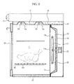
- FIGS. 1 and 2 are views illustrating the appearance and structure of a cooker according to one embodiment.
- a cooker 1 includes a housing 10 provided with a cooking area 11, and a door 30 hinge-bound to one side of the housing 10, to open or close an open front of the cooking area 11.
- the cooking area 11 is defined by a top plate 12, a bottom plate 13, two side plates 14 and a rear plate 15 and constituent components of the cooker are provided in an area between the outside of the cooking area 11 and the housing 10.
- the outside of the rear plate 15 is bound to a fan cover 20, and a convection fan 21 to circulate air through the cooking area 11 is provided interior the fan cover 20.
- a convection heater 22 is provided on the external circumference of the convection fan 21, and a fan motor 23, bound to the convection fan 21, is provided between the fan cover 20 and the rear plate 15 of the housing 10.
- Insulating members 16 may be arranged on the outside of the top plate 12, the bottom plate 13, the two side plates 14 and the fan cover 20 to define the cooking area 11, in order to insulate the cooking area 11 from the outside, and a control panel 17 to control the operation of an oven may be arranged on the top of the housing 10.
- a rail 14a to allow a rack 40 to be detachable is arranged on internal sides of the two side plates 14.
- the cooker 1 includes at least one heater 50 as a heat source to radiation-heat food placed on the cooking area 11.
- the convection heater 22 heats and the convection fan 21 rotates via a fan motor 23.
- air in the cooking area 11 is absorbed through the inlet holes 15a, is heated through the convection heater 22, and is supplied through the outlet holes 15b to the cooking area 11, and the supplied hot air cooks food, while circulating within the inside of the cooking area 11.
- the heater 50 for radiation heating is operated, the heater 50 directly radiation heats food in the cooking area 11.
- the convection heater 22 and the heater 50 for radiation heating operate together to heat food.
- one of the convection heater 22 and the radiation heater 50 may operate to heat food.
- the radiation heater 50 may be arranged on the cooking area 11, and for the arrangement of the radiation heater 50, an accepting member 12a may be provided on the top plate 12 of the cooking area 11. Both ends of the heater 50 pass through the accepting member 12a, extend to the outside of the cooking area 11 and are connected to power outside the cooking area 11.
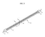
- FIG. 3 is a perspective view illustrating a heater for a cooker according to one embodiment
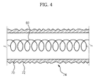
- FIG. 4 is a sectional view taken from the line I-I of FIG. 3 .
- the heater 50 includes a heat-generator 60 to generate heat when power is applied thereto, and a heater body 70 to accept the heat-generator 60.
- the heat-generator 60 may be made of a nickel-chromium wire or be in the form of a coil.
- a cap 80 is arranged on both ends of the heater body 70, and a lead wire 61 arranged on both ends of the heat-generator 60 passes through the cap 80 and extends to the outside of the heater body 70.
- the heat-generator 60 heats the heater body 70 and the heated heater body 70 heats foods by emitting a variety of wavelengths.
- Infrared rays are electromagnetic waves whose wavelength is longer than a red region of ultraviolet rays.
- Far-infrared rays refer to infrared rays having a wavelength of about 3 ⁇ m or higher. Far-infrared rays are readily absorbed by materials, and suited to cooking of food due to high resonance activity thereof to organic compounds.
- the heater body 70 includes a heat-radiation surface 72 to radiate heat to the cooking area 11, and the heat-radiation surface 72 of the heater body 70 includes a plurality of prominences/depressions 74.
- the prominences/depressions 74 scatter near-infrared wavelength energy passing through the heater body 70 to convert the same into far-infrared wavelength energy and thereby to improve far-infrared radiation efficiency of the heater 50.
- the prominences/depressions 74 of the heater body 70 may be finely formed by sandblasting.
- Sandblasting is a process in which fine sand is sprayed to a subject to be processed by a strong pressure to treat the surface of the subject.
- the use of sandblasting to process the heater body 70 enables control of the size of sand particles used to sandblast and thus determines optimal surface roughness of the heater body 70.
- the surface roughness of the heater body 70 to maximize far-infrared radiation efficiency may be varied.
- the heater body 70 is processed by sandblasting, surface roughness is readily varied by simply controlling the size of sand particles used for processing, thus easily realizing optimal surface roughness according to heater specifications.
- the heater body 70 may be provided in the form of a tube, and may be made of transparent quartz containing about 99% by weight or higher of silicon dioxide Si02.
- the heater body 70 may be manufactured by melting silicon dioxide having a purity of about 95% or higher, followed by extrusion-molding.
- Specimen 1 is transparent quartz containing silicon dioxide having a purity of about 95% or higher
- Specimen 2 is ceramic generally used for ceramic heaters
- Specimen 3 is transparent quartz, containing silicon dioxide having a purity of about 95% or higher, whose surface is sandblasted. The experiments were carried out at ambient temperature of approximately 20 to 22°C, and relative humidity of approximately 45 to 47%.
- the far-infrared radiation efficiency of Specimen 3 corresponding to the embodiment is higher than that of non-surface-treated quartz (Specimen 1), and is comparable to that of Specimen 2.
- Specimen 3 corresponding to the embodiment is cheaper than Specimen 2 and is thus more economical.
- the heater 50 according to the embodiment has advantages of both economical efficiency and performance.
Landscapes
- Engineering & Computer Science (AREA)
- Chemical & Material Sciences (AREA)
- Combustion & Propulsion (AREA)
- Mechanical Engineering (AREA)
- General Engineering & Computer Science (AREA)
- Physics & Mathematics (AREA)
- Electromagnetism (AREA)
- Resistance Heating (AREA)
- Electric Stoves And Ranges (AREA)
Applications Claiming Priority (1)
| Application Number | Priority Date | Filing Date | Title |
|---|---|---|---|
| KR1020080121038A KR20100062404A (ko) | 2008-12-02 | 2008-12-02 | 조리기기용 히터와 그 제조방법 및 조리기기 |
Publications (1)
| Publication Number | Publication Date |
|---|---|
| EP2194326A1 true EP2194326A1 (de) | 2010-06-09 |
Family
ID=42035546
Family Applications (1)
| Application Number | Title | Priority Date | Filing Date |
|---|---|---|---|
| EP09169102A Withdrawn EP2194326A1 (de) | 2008-12-02 | 2009-09-01 | Mit einem Kocher nutzbarer Heizung, Verfahren zur Herstellung davon und Kocher |
Country Status (3)
| Country | Link |
|---|---|
| US (1) | US20100133259A1 (de) |
| EP (1) | EP2194326A1 (de) |
| KR (1) | KR20100062404A (de) |
Families Citing this family (4)
| Publication number | Priority date | Publication date | Assignee | Title |
|---|---|---|---|---|
| KR101306792B1 (ko) * | 2011-06-14 | 2013-09-10 | 주식회사 나본 | 커피 머신에 있어서의 할로겐 히터를 구비한 커피 원두 로스팅용 케틀 |
| WO2017166457A1 (zh) * | 2016-03-30 | 2017-10-05 | 广东美的厨房电器制造有限公司 | 烹饪器具 |
| CN109951904A (zh) * | 2017-12-21 | 2019-06-28 | 李文庆 | 一种聚热石英管及其工艺方法 |
| KR102423267B1 (ko) * | 2018-01-23 | 2022-07-21 | 주식회사 원익아이피에스 | 히터 및 기판처리 장치 |
Citations (2)
| Publication number | Priority date | Publication date | Assignee | Title |
|---|---|---|---|---|
| EP0336436A2 (de) | 1988-04-08 | 1989-10-11 | Matsushita Electric Industrial Co., Ltd. | Zusammensetzung zur Herstellung einer im weiten Infrarotbereich emittierenden Schicht und ein im weiten Infrarotbereich emittierendes Heizelement |
| US20050173400A1 (en) | 2004-02-10 | 2005-08-11 | Hp Intellectual Corporation | Multi-purpose oven using infrared heating for reduced cooking time |
Family Cites Families (3)
| Publication number | Priority date | Publication date | Assignee | Title |
|---|---|---|---|---|
| US3450864A (en) * | 1967-05-24 | 1969-06-17 | Us Army | Elongated infrared heater |
| US4412126A (en) * | 1982-02-04 | 1983-10-25 | Sanders Associates, Inc. | Infrared source |
| US5417936A (en) * | 1992-06-08 | 1995-05-23 | Nippon Ozone Co., Ltd. | Plate-type ozone generator |
-
2008
- 2008-12-02 KR KR1020080121038A patent/KR20100062404A/ko not_active Withdrawn
-
2009
- 2009-08-17 US US12/461,588 patent/US20100133259A1/en not_active Abandoned
- 2009-09-01 EP EP09169102A patent/EP2194326A1/de not_active Withdrawn
Patent Citations (2)
| Publication number | Priority date | Publication date | Assignee | Title |
|---|---|---|---|---|
| EP0336436A2 (de) | 1988-04-08 | 1989-10-11 | Matsushita Electric Industrial Co., Ltd. | Zusammensetzung zur Herstellung einer im weiten Infrarotbereich emittierenden Schicht und ein im weiten Infrarotbereich emittierendes Heizelement |
| US20050173400A1 (en) | 2004-02-10 | 2005-08-11 | Hp Intellectual Corporation | Multi-purpose oven using infrared heating for reduced cooking time |
Also Published As
| Publication number | Publication date |
|---|---|
| US20100133259A1 (en) | 2010-06-03 |
| KR20100062404A (ko) | 2010-06-10 |
Similar Documents
| Publication | Publication Date | Title |
|---|---|---|
| CN101371756B (zh) | 具有多个烘烤加热器的电烤箱及预热该电烤箱的方法 | |
| CN107440476B (zh) | 烹饪设备及其控制方法 | |
| CN101086341B (zh) | 加热烹调器 | |
| KR102161799B1 (ko) | 에어 벤트 시스템을 포함하는 복합 가열식 곤충 건조기 | |
| US20100133259A1 (en) | Heater usable with cooker, method of manufacturing the same and cooker | |
| RU2521995C2 (ru) | Устройство для нагрева токами высокой частоты | |
| US8424450B2 (en) | Cooking apparatus | |
| CN101878672A (zh) | 炊具 | |
| JP6467158B2 (ja) | 高速加熱試験装置 | |
| JP4547344B2 (ja) | 加熱調理器 | |
| CN101696810B (zh) | 光波炉 | |
| CN1979000A (zh) | 热风对流加热装置的微波炉 | |
| CN201929690U (zh) | 一种烹饪装置 | |
| CN100487318C (zh) | 家庭电子烹调炉具 | |
| KR100646881B1 (ko) | 전기오븐레인지의 하부히터 차폐구조 | |
| JP6758336B2 (ja) | 加熱調理器 | |
| CN110383943B (zh) | 感应加热烹调器 | |
| CN204561882U (zh) | 电饼铛 | |
| KR101101511B1 (ko) | 조리기기의 제어방법 | |
| JP5492973B2 (ja) | 加熱調理器、および加熱調理器の製造方法 | |
| US20220381440A1 (en) | Electric range | |
| JP5694583B2 (ja) | 加熱調理器 | |
| KR20130063523A (ko) | 원적외선방사 불판 | |
| CN2653339Y (zh) | 带烧烤功能的微波炉 | |
| JPH0123042Y2 (de) |
Legal Events
| Date | Code | Title | Description |
|---|---|---|---|
| PUAI | Public reference made under article 153(3) epc to a published international application that has entered the european phase |
Free format text: ORIGINAL CODE: 0009012 |
|
| AK | Designated contracting states |
Kind code of ref document: A1 Designated state(s): AT BE BG CH CY CZ DE DK EE ES FI FR GB GR HR HU IE IS IT LI LT LU LV MC MK MT NL NO PL PT RO SE SI SK SM TR |
|
| 17P | Request for examination filed |
Effective date: 20101209 |
|
| 17Q | First examination report despatched |
Effective date: 20110517 |
|
| RAP1 | Party data changed (applicant data changed or rights of an application transferred) |
Owner name: SAMSUNG ELECTRONICS CO., LTD. |
|
| STAA | Information on the status of an ep patent application or granted ep patent |
Free format text: STATUS: THE APPLICATION IS DEEMED TO BE WITHDRAWN |
|
| 18D | Application deemed to be withdrawn |
Effective date: 20140401 |