EP2194330A2 - Klimaanlage und Steuerverfahren dafür - Google Patents
Klimaanlage und Steuerverfahren dafür Download PDFInfo
- Publication number
- EP2194330A2 EP2194330A2 EP09250794A EP09250794A EP2194330A2 EP 2194330 A2 EP2194330 A2 EP 2194330A2 EP 09250794 A EP09250794 A EP 09250794A EP 09250794 A EP09250794 A EP 09250794A EP 2194330 A2 EP2194330 A2 EP 2194330A2
- Authority
- EP
- European Patent Office
- Prior art keywords
- sensor
- air conditioner
- unit
- human body
- rotation
- Prior art date
- Legal status (The legal status is an assumption and is not a legal conclusion. Google has not performed a legal analysis and makes no representation as to the accuracy of the status listed.)
- Granted
Links
- 230000005855 radiation Effects 0.000 claims abstract description 64
- 238000001514 detection method Methods 0.000 claims abstract description 27
- 238000007599 discharging Methods 0.000 claims abstract description 4
- 230000011664 signaling Effects 0.000 claims abstract description 3
- 230000003321 amplification Effects 0.000 claims description 18
- 238000003199 nucleic acid amplification method Methods 0.000 claims description 18
- 238000005070 sampling Methods 0.000 claims description 7
- 239000003507 refrigerant Substances 0.000 description 17
- 230000001105 regulatory effect Effects 0.000 description 14
- 238000010586 diagram Methods 0.000 description 8
- 108010014173 Factor X Proteins 0.000 description 7
- 238000001816 cooling Methods 0.000 description 4
- 230000001276 controlling effect Effects 0.000 description 3
- 238000010438 heat treatment Methods 0.000 description 3
- 238000010276 construction Methods 0.000 description 2
- 230000000694 effects Effects 0.000 description 2
- 238000001914 filtration Methods 0.000 description 2
- 230000003287 optical effect Effects 0.000 description 2
- 238000000926 separation method Methods 0.000 description 2
- 230000004308 accommodation Effects 0.000 description 1
- 230000010354 integration Effects 0.000 description 1
Images







Classifications
-
- F—MECHANICAL ENGINEERING; LIGHTING; HEATING; WEAPONS; BLASTING
- F24—HEATING; RANGES; VENTILATING
- F24F—AIR-CONDITIONING; AIR-HUMIDIFICATION; VENTILATION; USE OF AIR CURRENTS FOR SCREENING
- F24F11/00—Control or safety arrangements
- F24F11/62—Control or safety arrangements characterised by the type of control or by internal processing, e.g. using fuzzy logic, adaptive control or estimation of values
- F24F11/63—Electronic processing
-
- F—MECHANICAL ENGINEERING; LIGHTING; HEATING; WEAPONS; BLASTING
- F24—HEATING; RANGES; VENTILATING
- F24F—AIR-CONDITIONING; AIR-HUMIDIFICATION; VENTILATION; USE OF AIR CURRENTS FOR SCREENING
- F24F11/00—Control or safety arrangements
- F24F11/30—Control or safety arrangements for purposes related to the operation of the system, e.g. for safety or monitoring
-
- F—MECHANICAL ENGINEERING; LIGHTING; HEATING; WEAPONS; BLASTING
- F24—HEATING; RANGES; VENTILATING
- F24F—AIR-CONDITIONING; AIR-HUMIDIFICATION; VENTILATION; USE OF AIR CURRENTS FOR SCREENING
- F24F11/00—Control or safety arrangements
- F24F11/50—Control or safety arrangements characterised by user interfaces or communication
- F24F11/52—Indication arrangements, e.g. displays
-
- F—MECHANICAL ENGINEERING; LIGHTING; HEATING; WEAPONS; BLASTING
- F24—HEATING; RANGES; VENTILATING
- F24F—AIR-CONDITIONING; AIR-HUMIDIFICATION; VENTILATION; USE OF AIR CURRENTS FOR SCREENING
- F24F11/00—Control or safety arrangements
- F24F11/70—Control systems characterised by their outputs; Constructional details thereof
- F24F11/72—Control systems characterised by their outputs; Constructional details thereof for controlling the supply of treated air, e.g. its pressure
- F24F11/74—Control systems characterised by their outputs; Constructional details thereof for controlling the supply of treated air, e.g. its pressure for controlling air flow rate or air velocity
-
- F—MECHANICAL ENGINEERING; LIGHTING; HEATING; WEAPONS; BLASTING
- F24—HEATING; RANGES; VENTILATING
- F24F—AIR-CONDITIONING; AIR-HUMIDIFICATION; VENTILATION; USE OF AIR CURRENTS FOR SCREENING
- F24F11/00—Control or safety arrangements
- F24F11/70—Control systems characterised by their outputs; Constructional details thereof
- F24F11/72—Control systems characterised by their outputs; Constructional details thereof for controlling the supply of treated air, e.g. its pressure
- F24F11/74—Control systems characterised by their outputs; Constructional details thereof for controlling the supply of treated air, e.g. its pressure for controlling air flow rate or air velocity
- F24F11/77—Control systems characterised by their outputs; Constructional details thereof for controlling the supply of treated air, e.g. its pressure for controlling air flow rate or air velocity by controlling the speed of ventilators
-
- F—MECHANICAL ENGINEERING; LIGHTING; HEATING; WEAPONS; BLASTING
- F24—HEATING; RANGES; VENTILATING
- F24F—AIR-CONDITIONING; AIR-HUMIDIFICATION; VENTILATION; USE OF AIR CURRENTS FOR SCREENING
- F24F11/00—Control or safety arrangements
- F24F11/70—Control systems characterised by their outputs; Constructional details thereof
- F24F11/72—Control systems characterised by their outputs; Constructional details thereof for controlling the supply of treated air, e.g. its pressure
- F24F11/79—Control systems characterised by their outputs; Constructional details thereof for controlling the supply of treated air, e.g. its pressure for controlling the direction of the supplied air
-
- F—MECHANICAL ENGINEERING; LIGHTING; HEATING; WEAPONS; BLASTING
- F24—HEATING; RANGES; VENTILATING
- F24F—AIR-CONDITIONING; AIR-HUMIDIFICATION; VENTILATION; USE OF AIR CURRENTS FOR SCREENING
- F24F2120/00—Control inputs relating to users or occupants
- F24F2120/10—Occupancy
-
- F—MECHANICAL ENGINEERING; LIGHTING; HEATING; WEAPONS; BLASTING
- F24—HEATING; RANGES; VENTILATING
- F24F—AIR-CONDITIONING; AIR-HUMIDIFICATION; VENTILATION; USE OF AIR CURRENTS FOR SCREENING
- F24F2120/00—Control inputs relating to users or occupants
- F24F2120/10—Occupancy
- F24F2120/12—Position of occupants
-
- Y—GENERAL TAGGING OF NEW TECHNOLOGICAL DEVELOPMENTS; GENERAL TAGGING OF CROSS-SECTIONAL TECHNOLOGIES SPANNING OVER SEVERAL SECTIONS OF THE IPC; TECHNICAL SUBJECTS COVERED BY FORMER USPC CROSS-REFERENCE ART COLLECTIONS [XRACs] AND DIGESTS
- Y02—TECHNOLOGIES OR APPLICATIONS FOR MITIGATION OR ADAPTATION AGAINST CLIMATE CHANGE
- Y02B—CLIMATE CHANGE MITIGATION TECHNOLOGIES RELATED TO BUILDINGS, e.g. HOUSING, HOUSE APPLIANCES OR RELATED END-USER APPLICATIONS
- Y02B30/00—Energy efficient heating, ventilation or air conditioning [HVAC]
- Y02B30/70—Efficient control or regulation technologies, e.g. for control of refrigerant flow, motor or heating
Definitions
- the present invention relates to an air conditioner which is capable of easily separating the human bodies and human body mistake factors from among heat sources within a room.
- air conditioners are household appliances for maintaining indoor air to a state which is most suitable for its use and purpose.
- the air conditioners may be configured to control the interior of a room in an air cooling state in summer and to control the interior of a room in a warm state in winter.
- the air conditioners may also be configured to control an indoor humidity and indoor air in a comfortable and clean state. With the gradual expansion and use of accommodation products in life, such as the air conditioners, consumers want products with high energy efficiency, improved performance, and convenient use.
- the air conditioners may be divided into a separate type air conditioner in which an indoor unit is separated from an outdoor unit, an integration type air conditioner in which an indoor unit and an outdoor unit are combined into one unit, a wall-mount air conditioner and a frame type air conditioner mounted on a wall, a slim type air conditioner configured to stand in a living room, a single type air conditioner configured to have a capacity capable of driving one indoor unit and installed at narrow places, such as homes, a large and medium-sized air conditioner configured to have a very large capacity and installed in companies or restaurants, a multi-type air conditioner configured to have a capacity enough to drive a number of indoor units.
- the invention provides an air conditioner which includes a discharge driving unit for discharging an air-conditioned air, a sensor module for detecting first and second radiation signals for heat sources while the sensor module rotates and performs scan in first and second rotation directions and for outputting a human body detection signal based on the detected first and second radiation signals, and a control unit for calculating position information of human bodies based on the human body detection signal and controlling the discharge driving unit based on the calculated position information.
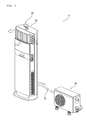
- FIG. 1 is a perspective view showing an air conditioner according to an embodiment of the present invention
- FIG. 2 is a simplified diagram showing the construction of the air conditioner shown in FIG. 1 .
- the air conditioner according to the embodiment of the present invention may be applied to any air conditioners, such as a stand type air conditioner, a wall-mount air conditioner, and a ceiling type air conditioner.
- a stand type air conditioner is described as an example, for convenience of description.
- the air conditioner 10 includes an indoor unit 20 and an outdoor unit 30.
- the indoor unit 20 and the outdoor unit 30 are coupled together by a refrigerant pipe 25.
- the indoor unit 20 includes a sensor module 40 for separating human bodies and human body mistake factors from among heat sources based on radiation signals for the radiation heats of the heat sources and outputting a human body detection signal.
- the sensor module 40 includes at least one infrared sensor.
- the indoor unit 20 includes an indoor heat exchanger 21 for performing heat exchange on an indoor air and refrigerants and an indoor ventilator (not shown) for improving the efficiency of the indoor heat exchanger 21 and at the same time circulating the indoor air.
- the outdoor unit 30 includes an outdoor heat exchanger 31 configured to perform heat exchange on an outdoor air and refrigerants, a regulated compressor 32 and an inverter compressor 34 configured to compress the refrigerants, a 4-way valve 36 configured to connect the refrigerants, discharged from the regulated compressor 32 and the inverter compressor 34, to the outdoor heat exchanger 31 or the indoor heat exchanger 21, an accumulator 38 configured to supply the refrigerants of a gaseous state to the regulated compressor 32 and the inverter compressor 34, and an oil separation unit placed between the inverter compressor 34 and the 4-way valve 36 and configured to separate oil from flowing refrigerants.
- the 4-way valve 36 switches the flow of the refrigerants and supplies the refrigerants, discharged from the regulated compressor 32 and the inverter compressor 34, to the outdoor heat exchanger 31 or the indoor heat exchanger 21.
- the accumulator 38 receives the refrigerants discharged from the 4-way valve 36 and supplies only the refrigerants of a gaseous state to the regulated compressor 32 and the inverter compressor 34.
- the regulated compressor 32 is configured to compress a certain amount of the refrigerants and discharge the compressed refrigerants.
- the inverter compressor 34 can control the amount of compressed refrigerants in a certain range and discharge a controlled amount of refrigerants.
- any one of or both the regulated compressor 32 and the inverter compressor 34 may be driven by a control unit (not shown) included in at least one of the indoor unit 20 and the outdoor unit 30.
- a control unit included in at least one of the indoor unit 20 and the outdoor unit 30.
- check valves may be placed on respective discharge-side refrigerant pipes of the regulated compressor 32 and the inverter compressor 34 in order for the refrigerants to be introduced into the other compressor.
- the air conditioner 10 is illustrated to include both the regulated compressor 32 and the inverter compressor 34, but may include only one of the regulated compressor 32 and the inverter compressor 34. Alternatively, the air conditioner 10 may include a plurality of the regulated compressors or a plurality of the inverter compressors.
- the accumulator 38, the regulated compressor 32, and the inverter compressor 34 are connected to each other via connection pipes 32a and 34a.
- the oil separation unit includes an oil separator 33 placed between a check valve and the inverter compressor 34, and a capillary tube 35 and a solenoid valve 37 placed between the oil separator 33 and the inverter compressor 34 and configured to bypass oil separated by the oil separator 33.
- the capillary tube 35 is placed on the part of the oil separator 33, and the solenoid valve 37 is placed on the entry side of the inverter compressor 34.
- the solenoid valve 37 is opened or shut at a predetermined cycle under the control of the controller of the air conditioner, so the oil separated by the oil separator 33 enters the entry side of the inverter compressor 34.
- the capacity of the regulated compressor 32 is greater than that of the inverter compressor 34.
- the inverter compressor 34 operates based on an indoor load capacity.
- FIG. 3 is a lateral view showing rotation recognition areas of the sensor module according to an embodiment of the present invention.
- the sensor module 40 mounted on the top of the indoor unit 20 rotates and detects the radiation heats of heat sources while scanning the rotation recognition areas.
- the sensor module 40 rotates and detects the radiation heats of heat sources (i.e., infrared rays emitted from the heat sources) by scanning the rotation recognition areas V1 and V2.
- heat sources i.e., infrared rays emitted from the heat sources
- the sensor module 40 scans the rotation recognition areas while rotating in a first rotation direction E1
- the sensor module 40 scans the rotation recognition areas, while rotating at a first speed, and generates a first radiation signal.
- the sensor module 40 scans the rotation recognition areas while rotating in a second rotation direction E2
- the sensor module 40 scans the rotation recognition areas, while rotating at a second speed, and generates a second radiation signal.
- the sensor module 40 separates human bodies and human body mistake factors from among the heat sources based on the first and second radiation signals and outputs a human body detection signal.
- the control unit of the indoor unit calculates the position information of the human bodies based on the human body detection signal and controls a discharge driving unit (not shown) based on the calculated position information so that the direction of the wind and the intensity of the wind of an air-conditioned air are controlled.
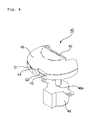
- FIG. 4 is a perspective view of the sensor module shown in FIG. 3
- FIG. 5 is an exploded perspective view of the sensor module shown in FIG. 4 .
- FIGS. 4 and 5 illustrate the sensor module 40 from a mechanical point of view.
- the sensor module 40 is mounted on the top of the indoor unit and is configured to rotate and detect the radiation heats of heat sources by scanning the interior of a room.
- the sensor module 40 includes a board 42, lenses 44 and 45, a casing 46, and a step motor 48.
- the board 42 may be a Printed Circuit Board (PCB) and is coupled to the rear side of the casing 46.
- a sensor unit 50 including first and second sensors 52 and 54, and a sensor control unit 56 are mounted on the board 42.
- the sensor control unit 56 transfers the first and second radiation signals for the radiation heats of the heat sources, detected by the first and second sensors 52 and 54, to the control unit (not shown) of the indoor unit 20 and controls the operation of the step motor 38.
- the sensor control unit 56 may be a micro controller.
- the sensor control unit 56 is a control unit (not shown), included in the indoor unit 20, and is configured to transfer the human body detection signal.
- the first and second sensors 52 and 54 detect the radiation heats of the heat sources within the first and second rotation recognition areas V1 and V2 and output the first and second radiation signals through a change in the voltage having a specific amount.
- the first and second sensors 52 and 54 detect the infrared rays and output the first and second radiation signals.
- the first and second sensors 52 and 54 may be infrared sensors or pyroelectric elements, or may be elements having the pyroelectric properties and a pyroelectric effect (i.e., an effect in which electromotive force is maintained by electric charges generated from a device surface in proportion to temperature).
- Each of the first and second sensors 52 and 54 includes a Cutrone filter which typically transmits the wavelength of an infrared area (7 ⁇ 14 ⁇ m) corresponding to an infrared wavelength band (6.5 ⁇ 15 ⁇ m) generated by the human bodies.
- the first and second sensors 52 and 54 further include respective electrodes for detecting electric charges, generated depending on a change in the temperature, in the form of voltage and for outputting the first and second radiation signals according to the detected electric charges.
- the lenses 44 and 45 are optical structures for focusing infrared rays incident on the sensor unit 50 and protecting the front side of the sensor unit 50.
- the lenses 44 and 45 are spaced apart from the sensor unit 50.
- the casing 46 protects the sensor unit 50 and integrates the board 42 and the sensor unit 50 into the lenses 44 and 45 (i.e., the optical structures).
- the casing 46 includes a rotation shaft 46a to which the step motor 48 is coupled so that the sensor unit 50 can rotate.
- the step motor 48 rotates the casing 46 so that the first and second sensors 52 and 54 rotate and detect infrared rays by scanning the first and second rotation recognition areas V1 and V2.
- step motor 48 rotates at the first or second speed in the clockwise and counterclockwise directions.
- the sensor module 40 is mounted on the outside top of the indoor unit 20.
- the sensor module 40 may be placed within the indoor unit 20 from which an air-conditioned air is discharged, but not limited thereto.
- FIG. 6 is a functional block diagram of the air conditioner according to an embodiment of the present invention.
- the air conditioner includes the sensor module 40 for outputting a human body detection signal P, a discharge driving unit 60 for discharging an air-conditioned air, a display unit 62 for displaying the direction of the wind and the intensity of the wind of the air-conditioned air and position information of the human bodies, and a control unit 64 for calculating the position information of the human bodies based on the human body detection signal P and controlling the discharge driving unit 60 and the display unit 62.
- the discharge driving unit 60 adjusts the direction of the wind of the air-conditioned air by controlling at least one of upper and lower vanes and right and left vanes from which the air-conditioned air is discharged.
- the display unit 62 displays the positions of the human bodies and human body mistake factors, which belong to heat sources, depending on the first and second rotation recognition areas (not shown) and the position information of the human bodies, scanned and detected by the sensor module 40, according to a control command from the control unit 64.
- the control unit 64 calculates intervals between the human bodies and the heights of the human bodies based on the position information of the human bodies and controls the discharge driving unit 60 and the display unit 62 based on the calculated information.
- the control unit 64 also controls the step motor (not shown), included in the sensor module 40, on the basis of the first or second rotation direction so that the step motor rotates at the first or second speed.
- control unit 64 controls the sensor module 40 at a point of time at which the human body detection signal P has been input (i.e., after the sensor module has performed scan while rotating in the first rotation direction E1) so that the sensor module 40 rotates in the second rotation direction E2.
- FIG. 7 is a functional block diagram of the sensor module shown in FIG. 6 .
- the sensor module 40 includes the sensor unit 50, the step motor 46, and the sensor control unit 56.
- the sensor unit 50 outputs first and second radiation signals A1_1 and A2_2 for the radiation heats C1 and C2 of heat sources in response to the first and second rotation directions E1 and E2.
- the step motor 46 rotates the sensor unit 50 in the first or second rotation direction E1 or E2.
- the sensor control unit 56 separates the human bodies and the human body mistake factors from among the heat sources on the basis of the first and second radiation signals A1_1 and A2_2 and outputs the human body detection signal P.
- the sensor unit 50 includes the first sensor 52 for detecting the first radiation heat C1 of a heat source within the first rotation recognition area V1 and the second sensor 54 for detecting the second radiation heat C2 of a heat sources within the second rotation recognition area V2.
- the first sensor 52 is inclined at a first predetermined angle and is configured to detect infrared rays emitted from the first rotation recognition area V1 (i.e., the first radiation heat C1 of the heat source).
- the second sensor 54 is inclined at a second predetermined angle and is configured to detect infrared rays emitted from the second rotation recognition area V2 (i.e., the second radiation heat C2 of the heat source).
- the first radiation signal A1_1 includes the first and second rotation radiation signals A1 and A2, which have been detected within the first and second rotation recognition areas V1 and V2 by the first and second sensors 52 and 54 which rotating in the first rotation direction E1.
- the second radiation signal A2_2 includes the third and fourth rotation radiation signals A3 and A4, which have been detected within the first and second rotation recognition areas V1 and V2 by the first and second sensors 52 and 54 which rotating in the second rotation direction E2.
- an angle, formed by the first predetermined angle of the first sensor 52 with the ground, may be smaller than an angle, formed by the second predetermined angle of the second sensor 54 with the ground.
- the first sensor 52 detects a close distance
- the second sensor 54 detects a long distance
- the step motor 46 is controlled by the control unit (not shown), included in the indoor unit 20, and is configured to rotate in the first or second rotation direction E1 or E2 at the first or second speed depending on a first or second mode.
- the step motor 46 may have a turning radius of 130 to 170°.
- the sensor control unit 56 includes an amplification unit 56a, a converter unit 56b, and a calculation processing unit 56c.
- the amplification unit 56a amplifies the first and second radiation signals A1_1 and A2_2 and outputs respective first and second amplification radiation signals B1 and B2.
- the converter unit 56b converts the first and second amplification radiation signals B1 and B2 into respective first and second digital signals D1 and D2.
- the calculation processing unit 56c separates the human bodies and the human body mistake factors from among the heat sources by performing a specific operation on the first and second digital signals D1 and D2 and outputs the human body detection signal P for the human bodies to the control unit 64.
- the converter unit 56b converts the first and second amplification radiation signals B1 and B2 into the first and second digital signals D1 and D2, respectively, through filtering and sampling.
- the calculation processing unit 56c separates the human bodies and the human body mistake factors from among the heat sources by performing a specific operation on the first and second digital signals D1 and D2 using a specific program.
- the calculation processing unit 55c separates and removes the human body mistake factors based on the first digital signal D1, scanned by the first and second sensors 52 and 54 while rotating in the first rotation direction E1, separates and removes the human body mistake factors based on the second digital signal D2, scanned by the first and second sensors 52 and 54 while rotating in the second rotation direction E2, and outputs the human body detection signal P for the human bodies, which belong to the heat sources.
- the control unit 64 controls the sensor module 40 at a point of time at which the human body detection signal P has been input (i.e., after the sensor module has performed scan while rotating in the first rotation direction E1) so that the sensor module 40 rotates in the second rotation direction E2. Further, the control unit 64 controls the discharge driving unit 60 on the basis of the human body detection signal P so that the air-conditioned air is discharged toward the human body.
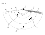
- FIG. 8 is a simplified view showing an operation when the sensor module shown in FIG. 6 rotates and performs scan in the first rotation direction
- FIG. 9 is a waveform showing the first radiation signal when the sensor module shown in FIG. 8 rotates and performs scan in the first rotation direction.
- FIGS. 8 and 9 are described in connection with the functional block diagram of FIG. 7 .
- the sensor module 40 detects heat sources U1, U2, and X placed within a room while rotating and performing scan in the first rotation direction E1.
- the sensor module 40 when the sensor module 40 rotates and performs scan in the first rotation direction E1, the sensor module 40 outputs the first radiation signal A1_1 based on the first and second rotation radiation signals A1 and A2, which have been respectively detected by the first and second sensors 52 and 54 from human bodies U1 and U2 and a human body mistake factor X, which belong to the heat sources U1, U2, and X within the first and second rotation recognition areas V1 and V2.
- the sensor module 40 rotates and performs scan in the first rotation direction E1
- the sensor module 40 moves at a first speed.
- the first speed is transferred to the control unit 56 so that the position of the human body mistake factor X from among the heat sources U1, U2, and X can be checked and the human body mistake factor X can be separated and removed.
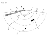
- FIG. 10 is a simplified view showing an operation when the sensor module shown in FIG. 6 rotates and performs scan in the second rotation direction
- FIG. 11 is a waveform showing the second radiation signal when the sensor module shown in FIG. 10 rotates and performs scan in the second rotation direction.
- FIGS. 10 and 11 are described in connection with the functional block diagram of FIG. 7 .
- the sensor module 40 detects heat sources U1, U2, and X placed within a room while rotating and performing scan in the second rotation direction E2.
- the sensor module 40 when the sensor module 40 rotates and performs scan in the second rotation direction E2, the sensor module 40 outputs the second radiation signal A2_2 based on the third and fourth rotation radiation signals A3 and A4, which have been respectively detected by the first and second sensors 52 and 54 from the human bodies U1 and U2 and the human body mistake factor X, which belong to the heat sources U1, U2, and X within the first and second rotation recognition areas V1 and V2.
- the sensor module 40 rotates and performs scan in the second rotation direction E2
- the sensor module 40 moves at a second speed.
- the second speed is transferred to the control unit 56 so that the position of the human body mistake factor X from among the heat sources U1, U2, and X can be checked and the human body mistake factor X can be separated and removed.
- FIG. 12 is a waveform showing the first and second amplification radiation signals respectively obtained by amplifying the first and second radiation signals shown in FIGS. 9 and 11
- FIG. 13 is a waveform showing the first and second digital signals respectively obtained by sampling the first and second amplification radiation signals shown in FIG. 12
- FIG. 14 is a waveform showing the human body detection signal converted from the first and second digital signals shown in FIG. 13 .
- the sensor control unit 56 receives the first and second radiation signals A1_1 and A2_2 from the first and second sensors 52 and 54.
- the amplification unit 56a outputs the first and second amplification radiation signals B1 and B2 respectively obtained by amplifying the first and second radiation signals A1_1 and A2_2 to a set amplification degree.
- the converter unit 56b generates the first and second digital signals D1 and D2 respectively obtained by sampling the first and second amplification radiation signals B1 and B2 according to a set sampling cycle.
- the converter unit 56b removes noises by filtering the first and second amplification radiation signals B1 and B2 and performs sampling.
- the sensor control unit 56c checks portions of the first and second digital signals D1 and D2, each having a first set value Z or more, based on the human body mistake factor X, removes the portions of the first and second digital signals D1 and D2, each having the first set value Z or more, by composing the first and second digital signals D1 and D2, and generates the human body detection signal P.
- the sensor control unit 56c transmits the human body detection signal P from which the human body mistake factors X from among the heat sources U1, U2, and X of the first and second digital signals D1 and D2 have been removed and in which only the human bodies U1 and U2 are detected to the control unit 64.
- the control unit 64 calculates the position information of the human bodies based on the intensity of the human body detection signal P.
- the position information of the human bodies may include at least one of an interval between the human bodies, and the directions and heights of the human bodies.
- the control unit 64 controls the discharge driving unit 40 based on at least one of an interval between the human bodies U1 and U2 and the directions and heights of the human bodies U1 and U2 so that the direction of the wind and the intensity of the wind of the air-conditioned air are changed.
Landscapes
- Engineering & Computer Science (AREA)
- Chemical & Material Sciences (AREA)
- Combustion & Propulsion (AREA)
- Mechanical Engineering (AREA)
- General Engineering & Computer Science (AREA)
- Physics & Mathematics (AREA)
- Signal Processing (AREA)
- Fluid Mechanics (AREA)
- Fuzzy Systems (AREA)
- Mathematical Physics (AREA)
- Human Computer Interaction (AREA)
- Air Conditioning Control Device (AREA)
Applications Claiming Priority (1)
| Application Number | Priority Date | Filing Date | Title |
|---|---|---|---|
| KR1020080122127A KR101591890B1 (ko) | 2008-12-03 | 2008-12-03 | 공기조화기 |
Publications (3)
| Publication Number | Publication Date |
|---|---|
| EP2194330A2 true EP2194330A2 (de) | 2010-06-09 |
| EP2194330A3 EP2194330A3 (de) | 2012-05-16 |
| EP2194330B1 EP2194330B1 (de) | 2014-04-30 |
Family
ID=41527951
Family Applications (1)
| Application Number | Title | Priority Date | Filing Date |
|---|---|---|---|
| EP09250794.6A Not-in-force EP2194330B1 (de) | 2008-12-03 | 2009-03-20 | Klimaanlage und Steuerverfahren dafür |
Country Status (4)
| Country | Link |
|---|---|
| US (1) | US8155792B2 (de) |
| EP (1) | EP2194330B1 (de) |
| KR (1) | KR101591890B1 (de) |
| CN (1) | CN101749800A (de) |
Cited By (2)
| Publication number | Priority date | Publication date | Assignee | Title |
|---|---|---|---|---|
| EP2960588A3 (de) * | 2014-06-25 | 2016-01-13 | Mitsubishi Electric Corporation | Inneneinheit einer klimaanlagenvorrichtung sowie klimaanlagenvorrichtung |
| EP3553401A3 (de) * | 2018-04-10 | 2019-12-25 | LG Electronics Inc. | Klimaanlage |
Families Citing this family (13)
| Publication number | Priority date | Publication date | Assignee | Title |
|---|---|---|---|---|
| KR101253239B1 (ko) * | 2008-03-11 | 2013-04-23 | 삼성전자주식회사 | 공기조화기 |
| KR101936749B1 (ko) * | 2012-09-28 | 2019-01-10 | 엘지전자 주식회사 | 이동식 이온 발생 장치 |
| KR102138502B1 (ko) * | 2013-06-19 | 2020-07-28 | 엘지전자 주식회사 | 인체감지용 안테나 유닛을 가지는 공기조화장치 |
| JP6170763B2 (ja) * | 2013-07-05 | 2017-07-26 | アズビル株式会社 | 表示装置および方法 |
| CN103727595B (zh) * | 2013-12-19 | 2016-05-11 | 宁波瑞易电器科技发展有限公司 | 一种空调调节系统 |
| CN104214899B (zh) * | 2014-09-02 | 2017-02-15 | 广东美的集团芜湖制冷设备有限公司 | 空调器风向控制方法和系统 |
| CN105651397A (zh) * | 2016-01-27 | 2016-06-08 | 四川长虹电器股份有限公司 | 一种精确识别人体温度的方法 |
| CN105757903A (zh) * | 2016-04-01 | 2016-07-13 | 广东美的制冷设备有限公司 | 一种空调器控制方法、系统及空调器 |
| CN107366974B (zh) * | 2017-08-30 | 2023-12-12 | 广东美的制冷设备有限公司 | 空调柜机 |
| CN108737727A (zh) * | 2018-04-27 | 2018-11-02 | 珠海格力电器股份有限公司 | 采集图像的方法和装置 |
| JP2021096050A (ja) * | 2019-12-18 | 2021-06-24 | 三菱電機株式会社 | 環境制御システム |
| JP7580586B2 (ja) * | 2021-05-10 | 2024-11-11 | 三菱電機株式会社 | 検査装置及び検査方法 |
| JP2023156114A (ja) * | 2022-04-12 | 2023-10-24 | シャープ株式会社 | 空気調和機 |
Citations (2)
| Publication number | Priority date | Publication date | Assignee | Title |
|---|---|---|---|---|
| US5331825A (en) | 1992-03-07 | 1994-07-26 | Samsung Electronics, Co., Ltd. | Air conditioning system |
| EP1985936A1 (de) | 2007-04-27 | 2008-10-29 | Samsung Electronics Co., Ltd. | Klimaanlage und Betriebsverfahren dafür |
Family Cites Families (36)
| Publication number | Priority date | Publication date | Assignee | Title |
|---|---|---|---|---|
| JPS57100504A (en) * | 1980-12-12 | 1982-06-22 | Nippon Denso Co Ltd | Controller |
| US4497031A (en) * | 1982-07-26 | 1985-01-29 | Johnson Service Company | Direct digital control apparatus for automated monitoring and control of building systems |
| US5103391A (en) * | 1987-11-06 | 1992-04-07 | M. T. Mcbrian Inc. | Control system for controlling environmental conditions in a closed building or other conditions |
| US5200644A (en) * | 1988-05-31 | 1993-04-06 | Kabushiki Kaisha Toshiba | Air conditioning system having battery for increasing efficiency |
| US5163399A (en) * | 1991-01-07 | 1992-11-17 | Saturn Corporation | Method for adjusting engine output power to compensate for loading due to a variable capacity air conditioning compressor |
| GB2260830B (en) | 1991-10-24 | 1994-10-19 | Norm Pacific Automat Corp | Ventilation device adjusted and controlled automatically with movement of human body |
| JP2755031B2 (ja) * | 1992-02-27 | 1998-05-20 | ダイキン工業株式会社 | 空気調和機 |
| JPH06160507A (ja) * | 1992-09-24 | 1994-06-07 | Matsushita Electric Ind Co Ltd | 人存在状況判定装置 |
| KR970010976B1 (ko) | 1993-12-31 | 1997-07-05 | 엘지전자 주식회사 | 적외선 어레이센서 장치 |
| US5621662A (en) * | 1994-02-15 | 1997-04-15 | Intellinet, Inc. | Home automation system |
| US6154686A (en) * | 1996-07-18 | 2000-11-28 | Innovex Technologies | Distributed architecture |
| US5988860A (en) * | 1996-07-18 | 1999-11-23 | Innovex Technologies, Inc. | System and method for directing air flow having a sash |
| JP3522053B2 (ja) * | 1996-08-26 | 2004-04-26 | トヨタ自動車株式会社 | 内燃機関の制御装置 |
| KR0182727B1 (ko) | 1996-10-08 | 1999-05-01 | 삼성전자주식회사 | 공기조화기의 풍향제어방법 |
| DE19837595B4 (de) * | 1998-08-19 | 2004-06-03 | Kuka Roboter Gmbh | Verfahren und Vorrichtung zum Gewichtsausgleich eines Roboterarms |
| JP4274293B2 (ja) | 1999-02-05 | 2009-06-03 | 三洋電機株式会社 | 空気調和機 |
| US6549826B1 (en) * | 2000-10-25 | 2003-04-15 | Honeywell International Inc. | VAV airflow control for preventing processor overflow and underflow |
| JP3807305B2 (ja) | 2001-12-28 | 2006-08-09 | ダイキン工業株式会社 | 空気調和機 |
| AU2003213017A1 (en) * | 2002-02-11 | 2003-09-04 | The Trustees Of Dartmouth College | Systems and methods for modifying an ice-to-object interface |
| US6735968B2 (en) * | 2002-03-29 | 2004-05-18 | Hitachi, Ltd. | Refrigerating apparatus and an inverter device used therein |
| US6840053B2 (en) * | 2003-01-27 | 2005-01-11 | Behr America, Inc. | Temperature control using infrared sensing |
| JP4029935B2 (ja) * | 2003-12-02 | 2008-01-09 | 株式会社日立製作所 | 冷凍装置及びインバータ装置 |
| US7173538B2 (en) * | 2004-06-25 | 2007-02-06 | Rm2, Inc. | Apparatus, system and method for monitoring a drying procedure |
| US7734381B2 (en) * | 2004-12-13 | 2010-06-08 | Innovive, Inc. | Controller for regulating airflow in rodent containment system |
| US7706928B1 (en) * | 2005-09-07 | 2010-04-27 | Admmicro Properties, Llc | Energy management system with security system interface |
| EP2060857B1 (de) * | 2006-09-07 | 2019-01-09 | Mitsubishi Electric Corporation | Klimaanlage |
| EP2087293A4 (de) * | 2006-11-28 | 2011-04-06 | Lg Electronics Inc | Klimaanlage und verfahren zur steuerung eines luftstroms damit |
| US8055388B2 (en) * | 2007-10-31 | 2011-11-08 | Illinois Tool Works Inc. | Maintenance and control system for ground support equipment |
| US8117864B2 (en) * | 2007-10-31 | 2012-02-21 | Illinois Tool Works Inc. | Compact, modularized air conditioning system that can be mounted upon an airplane ground support equipment cart |
| US20090107657A1 (en) * | 2007-10-31 | 2009-04-30 | Montminy Jeffrey E | Adjustable cooling system for airplane electronics |
| KR20090099296A (ko) * | 2008-03-17 | 2009-09-22 | 삼성전자주식회사 | 열원감지장치와 이를 갖는 가전기기 및 그 열원감지방법 |
| US7990092B2 (en) * | 2008-09-08 | 2011-08-02 | Nidec Motor Corporation | Blower motor for HVAC systems |
| US8362736B2 (en) * | 2008-09-08 | 2013-01-29 | Nidec Motor Corporation | Blower motor for HVAC systems |
| US8013551B2 (en) * | 2008-09-08 | 2011-09-06 | Nidec Motor Corporation | Blower motor for HVAC systems |
| US8362737B2 (en) * | 2008-09-08 | 2013-01-29 | Nidec Motor Corporation | Blower motor for HVAC systems |
| US8294393B2 (en) * | 2008-09-08 | 2012-10-23 | Nidec Motor Corporation | Blower motor for HVAC systems |
-
2008
- 2008-12-03 KR KR1020080122127A patent/KR101591890B1/ko not_active Expired - Fee Related
-
2009
- 2009-03-10 CN CN200910126391A patent/CN101749800A/zh active Pending
- 2009-03-20 EP EP09250794.6A patent/EP2194330B1/de not_active Not-in-force
- 2009-03-23 US US12/382,756 patent/US8155792B2/en not_active Expired - Fee Related
Patent Citations (2)
| Publication number | Priority date | Publication date | Assignee | Title |
|---|---|---|---|---|
| US5331825A (en) | 1992-03-07 | 1994-07-26 | Samsung Electronics, Co., Ltd. | Air conditioning system |
| EP1985936A1 (de) | 2007-04-27 | 2008-10-29 | Samsung Electronics Co., Ltd. | Klimaanlage und Betriebsverfahren dafür |
Cited By (4)
| Publication number | Priority date | Publication date | Assignee | Title |
|---|---|---|---|---|
| EP2960588A3 (de) * | 2014-06-25 | 2016-01-13 | Mitsubishi Electric Corporation | Inneneinheit einer klimaanlagenvorrichtung sowie klimaanlagenvorrichtung |
| US10024563B2 (en) | 2014-06-25 | 2018-07-17 | Mitsubishi Electric Corporation | Indoor unit of air-conditioning apparatus and air-conditioning apparatus |
| EP3553401A3 (de) * | 2018-04-10 | 2019-12-25 | LG Electronics Inc. | Klimaanlage |
| US11301779B2 (en) | 2018-04-10 | 2022-04-12 | Lg Electronics Inc. | Air conditioner |
Also Published As
| Publication number | Publication date |
|---|---|
| KR20100063559A (ko) | 2010-06-11 |
| US8155792B2 (en) | 2012-04-10 |
| KR101591890B1 (ko) | 2016-02-04 |
| US20100138048A1 (en) | 2010-06-03 |
| CN101749800A (zh) | 2010-06-23 |
| EP2194330B1 (de) | 2014-04-30 |
| EP2194330A3 (de) | 2012-05-16 |
Similar Documents
| Publication | Publication Date | Title |
|---|---|---|
| EP2194330B1 (de) | Klimaanlage und Steuerverfahren dafür | |
| US8204627B2 (en) | Air conditioner and method of controlling the same | |
| EP2372261B1 (de) | Klimaanlage, die photovoltaische Energie verwendet | |
| KR102295969B1 (ko) | 공기조화기 및 그 제어방법 | |
| EP2395291A2 (de) | Klimaanlage | |
| KR102262245B1 (ko) | 공기조화기 및 그 제어방법 | |
| KR20090081919A (ko) | 공기조화기 및 그 제어방법 | |
| KR20090084478A (ko) | 공기조화기 및 그 제어방법 | |
| US9726408B2 (en) | Air conditioner | |
| KR20210146019A (ko) | 공조 시스템 및 그 동작 방법 | |
| JP2000097483A (ja) | 空気調和機 | |
| US20230090958A1 (en) | Self-contained data logging air measurement device | |
| KR101869092B1 (ko) | 태양전지를 구비한 공기조화기 | |
| KR100876982B1 (ko) | 자가 밸런싱 로터열교환기를 구비한 공기조화기 및 그 자가밸런싱 방법 | |
| CN221222941U (zh) | 传感模块、顶置式室内单元和空调装置 | |
| KR20090085369A (ko) | 공기조화기 및 그 제어방법 | |
| KR101064372B1 (ko) | 멀티 공기조화기의 냉매 제어장치 | |
| JP2021032474A (ja) | 空気調和システム | |
| KR20100106822A (ko) | 공기조화기 | |
| KR20090081918A (ko) | 공기조화기 및 그 제어방법 | |
| KR20050105736A (ko) | 공기조화기 및 그 제어방법 | |
| KR101501947B1 (ko) | 공기조화기 및 그 제어방법 | |
| CN119901060A (zh) | 空调装置 | |
| WO2024166342A1 (ja) | 空気調和装置の室内機および空気調和システム | |
| KR20260027698A (ko) | 전기 집진 장치, 그 전기 집진 장치의 제어 방법, 및 그 전기 집진 장치를 포함하는 공기조화기 |
Legal Events
| Date | Code | Title | Description |
|---|---|---|---|
| PUAI | Public reference made under article 153(3) epc to a published international application that has entered the european phase |
Free format text: ORIGINAL CODE: 0009012 |
|
| AK | Designated contracting states |
Kind code of ref document: A2 Designated state(s): AT BE BG CH CY CZ DE DK EE ES FI FR GB GR HR HU IE IS IT LI LT LU LV MC MK MT NL NO PL PT RO SE SI SK TR |
|
| AX | Request for extension of the european patent |
Extension state: AL BA RS |
|
| PUAL | Search report despatched |
Free format text: ORIGINAL CODE: 0009013 |
|
| AK | Designated contracting states |
Kind code of ref document: A3 Designated state(s): AT BE BG CH CY CZ DE DK EE ES FI FR GB GR HR HU IE IS IT LI LT LU LV MC MK MT NL NO PL PT RO SE SI SK TR |
|
| AX | Request for extension of the european patent |
Extension state: AL BA RS |
|
| RIC1 | Information provided on ipc code assigned before grant |
Ipc: F24F 11/00 20060101AFI20120411BHEP |
|
| 17P | Request for examination filed |
Effective date: 20121116 |
|
| AKX | Designation fees paid |
Designated state(s): AT BE BG CH CY CZ DE DK EE ES FI FR GB GR HR HU IE IS IT LI LT LU LV MC MK MT NL NO PL PT RO SE SI SK TR |
|
| GRAP | Despatch of communication of intention to grant a patent |
Free format text: ORIGINAL CODE: EPIDOSNIGR1 |
|
| RAP1 | Party data changed (applicant data changed or rights of an application transferred) |
Owner name: LG ELECTRONICS INC. |
|
| RIN1 | Information on inventor provided before grant (corrected) |
Inventor name: PARK, HEE WOONG Inventor name: PARK, NAE HYUN Inventor name: KIM, DONG JU |
|
| INTG | Intention to grant announced |
Effective date: 20130405 |
|
| GRAP | Despatch of communication of intention to grant a patent |
Free format text: ORIGINAL CODE: EPIDOSNIGR1 |
|
| INTG | Intention to grant announced |
Effective date: 20131014 |
|
| GRAS | Grant fee paid |
Free format text: ORIGINAL CODE: EPIDOSNIGR3 |
|
| GRAA | (expected) grant |
Free format text: ORIGINAL CODE: 0009210 |
|
| AK | Designated contracting states |
Kind code of ref document: B1 Designated state(s): AT BE BG CH CY CZ DE DK EE ES FI FR GB GR HR HU IE IS IT LI LT LU LV MC MK MT NL NO PL PT RO SE SI SK TR |
|
| REG | Reference to a national code |
Ref country code: GB Ref legal event code: FG4D Ref country code: CH Ref legal event code: EP |
|
| REG | Reference to a national code |
Ref country code: AT Ref legal event code: REF Ref document number: 665407 Country of ref document: AT Kind code of ref document: T Effective date: 20140515 |
|
| REG | Reference to a national code |
Ref country code: IE Ref legal event code: FG4D |
|
| REG | Reference to a national code |
Ref country code: DE Ref legal event code: R096 Ref document number: 602009023648 Country of ref document: DE Effective date: 20140612 |
|
| REG | Reference to a national code |
Ref country code: AT Ref legal event code: MK05 Ref document number: 665407 Country of ref document: AT Kind code of ref document: T Effective date: 20140430 |
|
| REG | Reference to a national code |
Ref country code: LT Ref legal event code: MG4D |
|
| REG | Reference to a national code |
Ref country code: NL Ref legal event code: VDEP Effective date: 20140430 |
|
| PG25 | Lapsed in a contracting state [announced via postgrant information from national office to epo] |
Ref country code: LT Free format text: LAPSE BECAUSE OF FAILURE TO SUBMIT A TRANSLATION OF THE DESCRIPTION OR TO PAY THE FEE WITHIN THE PRESCRIBED TIME-LIMIT Effective date: 20140430 Ref country code: IS Free format text: LAPSE BECAUSE OF FAILURE TO SUBMIT A TRANSLATION OF THE DESCRIPTION OR TO PAY THE FEE WITHIN THE PRESCRIBED TIME-LIMIT Effective date: 20140830 Ref country code: GR Free format text: LAPSE BECAUSE OF FAILURE TO SUBMIT A TRANSLATION OF THE DESCRIPTION OR TO PAY THE FEE WITHIN THE PRESCRIBED TIME-LIMIT Effective date: 20140731 Ref country code: NL Free format text: LAPSE BECAUSE OF FAILURE TO SUBMIT A TRANSLATION OF THE DESCRIPTION OR TO PAY THE FEE WITHIN THE PRESCRIBED TIME-LIMIT Effective date: 20140430 Ref country code: CY Free format text: LAPSE BECAUSE OF FAILURE TO SUBMIT A TRANSLATION OF THE DESCRIPTION OR TO PAY THE FEE WITHIN THE PRESCRIBED TIME-LIMIT Effective date: 20140430 Ref country code: NO Free format text: LAPSE BECAUSE OF FAILURE TO SUBMIT A TRANSLATION OF THE DESCRIPTION OR TO PAY THE FEE WITHIN THE PRESCRIBED TIME-LIMIT Effective date: 20140730 Ref country code: BG Free format text: LAPSE BECAUSE OF FAILURE TO SUBMIT A TRANSLATION OF THE DESCRIPTION OR TO PAY THE FEE WITHIN THE PRESCRIBED TIME-LIMIT Effective date: 20140730 Ref country code: FI Free format text: LAPSE BECAUSE OF FAILURE TO SUBMIT A TRANSLATION OF THE DESCRIPTION OR TO PAY THE FEE WITHIN THE PRESCRIBED TIME-LIMIT Effective date: 20140430 |
|
| PG25 | Lapsed in a contracting state [announced via postgrant information from national office to epo] |
Ref country code: AT Free format text: LAPSE BECAUSE OF FAILURE TO SUBMIT A TRANSLATION OF THE DESCRIPTION OR TO PAY THE FEE WITHIN THE PRESCRIBED TIME-LIMIT Effective date: 20140430 Ref country code: HR Free format text: LAPSE BECAUSE OF FAILURE TO SUBMIT A TRANSLATION OF THE DESCRIPTION OR TO PAY THE FEE WITHIN THE PRESCRIBED TIME-LIMIT Effective date: 20140430 Ref country code: LV Free format text: LAPSE BECAUSE OF FAILURE TO SUBMIT A TRANSLATION OF THE DESCRIPTION OR TO PAY THE FEE WITHIN THE PRESCRIBED TIME-LIMIT Effective date: 20140430 Ref country code: ES Free format text: LAPSE BECAUSE OF FAILURE TO SUBMIT A TRANSLATION OF THE DESCRIPTION OR TO PAY THE FEE WITHIN THE PRESCRIBED TIME-LIMIT Effective date: 20140430 Ref country code: SE Free format text: LAPSE BECAUSE OF FAILURE TO SUBMIT A TRANSLATION OF THE DESCRIPTION OR TO PAY THE FEE WITHIN THE PRESCRIBED TIME-LIMIT Effective date: 20140430 Ref country code: PL Free format text: LAPSE BECAUSE OF FAILURE TO SUBMIT A TRANSLATION OF THE DESCRIPTION OR TO PAY THE FEE WITHIN THE PRESCRIBED TIME-LIMIT Effective date: 20140430 |
|
| PG25 | Lapsed in a contracting state [announced via postgrant information from national office to epo] |
Ref country code: PT Free format text: LAPSE BECAUSE OF FAILURE TO SUBMIT A TRANSLATION OF THE DESCRIPTION OR TO PAY THE FEE WITHIN THE PRESCRIBED TIME-LIMIT Effective date: 20140901 |
|
| PG25 | Lapsed in a contracting state [announced via postgrant information from national office to epo] |
Ref country code: EE Free format text: LAPSE BECAUSE OF FAILURE TO SUBMIT A TRANSLATION OF THE DESCRIPTION OR TO PAY THE FEE WITHIN THE PRESCRIBED TIME-LIMIT Effective date: 20140430 Ref country code: BE Free format text: LAPSE BECAUSE OF FAILURE TO SUBMIT A TRANSLATION OF THE DESCRIPTION OR TO PAY THE FEE WITHIN THE PRESCRIBED TIME-LIMIT Effective date: 20140430 Ref country code: SK Free format text: LAPSE BECAUSE OF FAILURE TO SUBMIT A TRANSLATION OF THE DESCRIPTION OR TO PAY THE FEE WITHIN THE PRESCRIBED TIME-LIMIT Effective date: 20140430 Ref country code: RO Free format text: LAPSE BECAUSE OF FAILURE TO SUBMIT A TRANSLATION OF THE DESCRIPTION OR TO PAY THE FEE WITHIN THE PRESCRIBED TIME-LIMIT Effective date: 20140430 Ref country code: DK Free format text: LAPSE BECAUSE OF FAILURE TO SUBMIT A TRANSLATION OF THE DESCRIPTION OR TO PAY THE FEE WITHIN THE PRESCRIBED TIME-LIMIT Effective date: 20140430 Ref country code: CZ Free format text: LAPSE BECAUSE OF FAILURE TO SUBMIT A TRANSLATION OF THE DESCRIPTION OR TO PAY THE FEE WITHIN THE PRESCRIBED TIME-LIMIT Effective date: 20140430 |
|
| REG | Reference to a national code |
Ref country code: DE Ref legal event code: R097 Ref document number: 602009023648 Country of ref document: DE |
|
| PLBE | No opposition filed within time limit |
Free format text: ORIGINAL CODE: 0009261 |
|
| STAA | Information on the status of an ep patent application or granted ep patent |
Free format text: STATUS: NO OPPOSITION FILED WITHIN TIME LIMIT |
|
| 26N | No opposition filed |
Effective date: 20150202 |
|
| REG | Reference to a national code |
Ref country code: DE Ref legal event code: R097 Ref document number: 602009023648 Country of ref document: DE Effective date: 20150202 |
|
| PG25 | Lapsed in a contracting state [announced via postgrant information from national office to epo] |
Ref country code: SI Free format text: LAPSE BECAUSE OF FAILURE TO SUBMIT A TRANSLATION OF THE DESCRIPTION OR TO PAY THE FEE WITHIN THE PRESCRIBED TIME-LIMIT Effective date: 20140430 |
|
| PG25 | Lapsed in a contracting state [announced via postgrant information from national office to epo] |
Ref country code: LU Free format text: LAPSE BECAUSE OF FAILURE TO SUBMIT A TRANSLATION OF THE DESCRIPTION OR TO PAY THE FEE WITHIN THE PRESCRIBED TIME-LIMIT Effective date: 20150320 Ref country code: MC Free format text: LAPSE BECAUSE OF FAILURE TO SUBMIT A TRANSLATION OF THE DESCRIPTION OR TO PAY THE FEE WITHIN THE PRESCRIBED TIME-LIMIT Effective date: 20140430 |
|
| REG | Reference to a national code |
Ref country code: CH Ref legal event code: PL |
|
| GBPC | Gb: european patent ceased through non-payment of renewal fee |
Effective date: 20150320 |
|
| REG | Reference to a national code |
Ref country code: FR Ref legal event code: ST Effective date: 20151130 |
|
| REG | Reference to a national code |
Ref country code: IE Ref legal event code: MM4A |
|
| PG25 | Lapsed in a contracting state [announced via postgrant information from national office to epo] |
Ref country code: CH Free format text: LAPSE BECAUSE OF NON-PAYMENT OF DUE FEES Effective date: 20150331 Ref country code: IE Free format text: LAPSE BECAUSE OF NON-PAYMENT OF DUE FEES Effective date: 20150320 Ref country code: LI Free format text: LAPSE BECAUSE OF NON-PAYMENT OF DUE FEES Effective date: 20150331 Ref country code: GB Free format text: LAPSE BECAUSE OF NON-PAYMENT OF DUE FEES Effective date: 20150320 |
|
| PG25 | Lapsed in a contracting state [announced via postgrant information from national office to epo] |
Ref country code: FR Free format text: LAPSE BECAUSE OF NON-PAYMENT OF DUE FEES Effective date: 20150331 |
|
| PG25 | Lapsed in a contracting state [announced via postgrant information from national office to epo] |
Ref country code: MT Free format text: LAPSE BECAUSE OF FAILURE TO SUBMIT A TRANSLATION OF THE DESCRIPTION OR TO PAY THE FEE WITHIN THE PRESCRIBED TIME-LIMIT Effective date: 20140430 |
|
| PG25 | Lapsed in a contracting state [announced via postgrant information from national office to epo] |
Ref country code: HU Free format text: LAPSE BECAUSE OF FAILURE TO SUBMIT A TRANSLATION OF THE DESCRIPTION OR TO PAY THE FEE WITHIN THE PRESCRIBED TIME-LIMIT; INVALID AB INITIO Effective date: 20090320 |
|
| PG25 | Lapsed in a contracting state [announced via postgrant information from national office to epo] |
Ref country code: TR Free format text: LAPSE BECAUSE OF FAILURE TO SUBMIT A TRANSLATION OF THE DESCRIPTION OR TO PAY THE FEE WITHIN THE PRESCRIBED TIME-LIMIT Effective date: 20140430 |
|
| PGFP | Annual fee paid to national office [announced via postgrant information from national office to epo] |
Ref country code: IT Payment date: 20180312 Year of fee payment: 10 |
|
| PG25 | Lapsed in a contracting state [announced via postgrant information from national office to epo] |
Ref country code: MK Free format text: LAPSE BECAUSE OF FAILURE TO SUBMIT A TRANSLATION OF THE DESCRIPTION OR TO PAY THE FEE WITHIN THE PRESCRIBED TIME-LIMIT Effective date: 20140430 |
|
| PG25 | Lapsed in a contracting state [announced via postgrant information from national office to epo] |
Ref country code: IT Free format text: LAPSE BECAUSE OF NON-PAYMENT OF DUE FEES Effective date: 20190320 |
|
| PGFP | Annual fee paid to national office [announced via postgrant information from national office to epo] |
Ref country code: DE Payment date: 20230206 Year of fee payment: 15 |
|
| REG | Reference to a national code |
Ref country code: DE Ref legal event code: R119 Ref document number: 602009023648 Country of ref document: DE |
|
| PG25 | Lapsed in a contracting state [announced via postgrant information from national office to epo] |
Ref country code: DE Free format text: LAPSE BECAUSE OF NON-PAYMENT OF DUE FEES Effective date: 20241001 |
|
| PG25 | Lapsed in a contracting state [announced via postgrant information from national office to epo] |
Ref country code: DE Free format text: LAPSE BECAUSE OF NON-PAYMENT OF DUE FEES Effective date: 20241001 |