EP2194372B1 - Procédé de détection par fluorescence - Google Patents
Procédé de détection par fluorescence Download PDFInfo
- Publication number
- EP2194372B1 EP2194372B1 EP08833299.4A EP08833299A EP2194372B1 EP 2194372 B1 EP2194372 B1 EP 2194372B1 EP 08833299 A EP08833299 A EP 08833299A EP 2194372 B1 EP2194372 B1 EP 2194372B1
- Authority
- EP
- European Patent Office
- Prior art keywords
- fluorescence
- microchip
- fluorescence intensity
- emitted
- excitation light
- Prior art date
- Legal status (The legal status is an assumption and is not a legal conclusion. Google has not performed a legal analysis and makes no representation as to the accuracy of the status listed.)
- Active
Links
- 238000000034 method Methods 0.000 title claims description 36
- 238000001917 fluorescence detection Methods 0.000 title claims description 31
- 230000005284 excitation Effects 0.000 claims description 78
- 230000002123 temporal effect Effects 0.000 claims description 78
- 239000012472 biological sample Substances 0.000 claims description 73
- 230000008859 change Effects 0.000 claims description 66
- 238000001514 detection method Methods 0.000 claims description 20
- 239000000463 material Substances 0.000 claims description 20
- 239000000126 substance Substances 0.000 description 14
- 230000000694 effects Effects 0.000 description 9
- 230000006870 function Effects 0.000 description 7
- 238000001962 electrophoresis Methods 0.000 description 6
- 229920003229 poly(methyl methacrylate) Polymers 0.000 description 6
- 239000011347 resin Substances 0.000 description 6
- 229920005989 resin Polymers 0.000 description 6
- VYPSYNLAJGMNEJ-UHFFFAOYSA-N Silicium dioxide Chemical compound O=[Si]=O VYPSYNLAJGMNEJ-UHFFFAOYSA-N 0.000 description 5
- 238000002493 microarray Methods 0.000 description 5
- 239000004926 polymethyl methacrylate Substances 0.000 description 5
- 238000010586 diagram Methods 0.000 description 4
- 108090000623 proteins and genes Proteins 0.000 description 4
- 102000004190 Enzymes Human genes 0.000 description 3
- 108090000790 Enzymes Proteins 0.000 description 3
- 238000004458 analytical method Methods 0.000 description 3
- 230000002238 attenuated effect Effects 0.000 description 3
- 239000002981 blocking agent Substances 0.000 description 3
- 102000004169 proteins and genes Human genes 0.000 description 3
- 239000000427 antigen Substances 0.000 description 2
- 102000036639 antigens Human genes 0.000 description 2
- 108091007433 antigens Proteins 0.000 description 2
- 239000002299 complementary DNA Substances 0.000 description 2
- 239000012530 fluid Substances 0.000 description 2
- 239000007850 fluorescent dye Substances 0.000 description 2
- 239000005556 hormone Substances 0.000 description 2
- 229940088597 hormone Drugs 0.000 description 2
- 238000003384 imaging method Methods 0.000 description 2
- 238000004519 manufacturing process Methods 0.000 description 2
- 238000005259 measurement Methods 0.000 description 2
- 108020004707 nucleic acids Proteins 0.000 description 2
- 102000039446 nucleic acids Human genes 0.000 description 2
- 150000007523 nucleic acids Chemical class 0.000 description 2
- 230000003287 optical effect Effects 0.000 description 2
- 230000008569 process Effects 0.000 description 2
- 239000000439 tumor marker Substances 0.000 description 2
- 108091032973 (ribonucleotides)n+m Proteins 0.000 description 1
- PPBRXRYQALVLMV-UHFFFAOYSA-N Styrene Chemical compound C=CC1=CC=CC=C1 PPBRXRYQALVLMV-UHFFFAOYSA-N 0.000 description 1
- 238000007385 chemical modification Methods 0.000 description 1
- 238000011156 evaluation Methods 0.000 description 1
- 238000000605 extraction Methods 0.000 description 1
- 230000014509 gene expression Effects 0.000 description 1
- 239000011521 glass Substances 0.000 description 1
- 238000009396 hybridization Methods 0.000 description 1
- 238000003018 immunoassay Methods 0.000 description 1
- 239000003547 immunosorbent Substances 0.000 description 1
- 238000002955 isolation Methods 0.000 description 1
- 239000012528 membrane Substances 0.000 description 1
- 108020004999 messenger RNA Proteins 0.000 description 1
- 238000010208 microarray analysis Methods 0.000 description 1
- 239000000203 mixture Substances 0.000 description 1
- 238000012545 processing Methods 0.000 description 1
- 230000009467 reduction Effects 0.000 description 1
- 238000000926 separation method Methods 0.000 description 1
- 230000009870 specific binding Effects 0.000 description 1
Images



Classifications
-
- G—PHYSICS
- G01—MEASURING; TESTING
- G01N—INVESTIGATING OR ANALYSING MATERIALS BY DETERMINING THEIR CHEMICAL OR PHYSICAL PROPERTIES
- G01N21/00—Investigating or analysing materials by the use of optical means, i.e. using sub-millimetre waves, infrared, visible or ultraviolet light
- G01N21/62—Systems in which the material investigated is excited whereby it emits light or causes a change in wavelength of the incident light
- G01N21/63—Systems in which the material investigated is excited whereby it emits light or causes a change in wavelength of the incident light optically excited
- G01N21/64—Fluorescence; Phosphorescence
- G01N21/6428—Measuring fluorescence of fluorescent products of reactions or of fluorochrome labelled reactive substances, e.g. measuring quenching effects, using measuring "optrodes"
-
- G—PHYSICS
- G01—MEASURING; TESTING
- G01N—INVESTIGATING OR ANALYSING MATERIALS BY DETERMINING THEIR CHEMICAL OR PHYSICAL PROPERTIES
- G01N21/00—Investigating or analysing materials by the use of optical means, i.e. using sub-millimetre waves, infrared, visible or ultraviolet light
- G01N21/62—Systems in which the material investigated is excited whereby it emits light or causes a change in wavelength of the incident light
- G01N21/63—Systems in which the material investigated is excited whereby it emits light or causes a change in wavelength of the incident light optically excited
- G01N21/64—Fluorescence; Phosphorescence
- G01N21/6408—Fluorescence; Phosphorescence with measurement of decay time, time resolved fluorescence
-
- G—PHYSICS
- G01—MEASURING; TESTING
- G01N—INVESTIGATING OR ANALYSING MATERIALS BY DETERMINING THEIR CHEMICAL OR PHYSICAL PROPERTIES
- G01N27/00—Investigating or analysing materials by the use of electric, electrochemical, or magnetic means
- G01N27/26—Investigating or analysing materials by the use of electric, electrochemical, or magnetic means by investigating electrochemical variables; by using electrolysis or electrophoresis
- G01N27/416—Systems
- G01N27/447—Systems using electrophoresis
- G01N27/44704—Details; Accessories
- G01N27/44717—Arrangements for investigating the separated zones, e.g. localising zones
- G01N27/44721—Arrangements for investigating the separated zones, e.g. localising zones by optical means
- G01N27/44726—Arrangements for investigating the separated zones, e.g. localising zones by optical means using specific dyes, markers or binding molecules
-
- G—PHYSICS
- G01—MEASURING; TESTING
- G01N—INVESTIGATING OR ANALYSING MATERIALS BY DETERMINING THEIR CHEMICAL OR PHYSICAL PROPERTIES
- G01N21/00—Investigating or analysing materials by the use of optical means, i.e. using sub-millimetre waves, infrared, visible or ultraviolet light
- G01N21/01—Arrangements or apparatus for facilitating the optical investigation
- G01N21/03—Cuvette constructions
- G01N2021/0346—Capillary cells; Microcells
-
- G—PHYSICS
- G01—MEASURING; TESTING
- G01N—INVESTIGATING OR ANALYSING MATERIALS BY DETERMINING THEIR CHEMICAL OR PHYSICAL PROPERTIES
- G01N21/00—Investigating or analysing materials by the use of optical means, i.e. using sub-millimetre waves, infrared, visible or ultraviolet light
- G01N21/01—Arrangements or apparatus for facilitating the optical investigation
- G01N21/03—Cuvette constructions
- G01N21/05—Flow-through cuvettes
-
- G—PHYSICS
- G01—MEASURING; TESTING
- G01N—INVESTIGATING OR ANALYSING MATERIALS BY DETERMINING THEIR CHEMICAL OR PHYSICAL PROPERTIES
- G01N21/00—Investigating or analysing materials by the use of optical means, i.e. using sub-millimetre waves, infrared, visible or ultraviolet light
- G01N21/62—Systems in which the material investigated is excited whereby it emits light or causes a change in wavelength of the incident light
- G01N21/63—Systems in which the material investigated is excited whereby it emits light or causes a change in wavelength of the incident light optically excited
- G01N21/64—Fluorescence; Phosphorescence
- G01N21/645—Specially adapted constructive features of fluorimeters
- G01N21/6456—Spatial resolved fluorescence measurements; Imaging
- G01N21/6458—Fluorescence microscopy
Definitions
- the present invention relates to a fluorescence detection method in which a fluorescently-labeled biological sample is fed to a microchip and excitation light is applied thereto to detect an intensity of emitted fluorescence.
- Fluorescence detection methods for detecting an intensity of fluorescence which is emitted from a fluorescently-labeled biological sample have conventionally been known. According to the fluorescence detection methods, separation or identification of a gene sequence, a level of gene expression, or a protein, or evaluation of a molecular weight or a property can be achieved by detecting the fluorescence intensity.
- ⁇ TAS-immunoassay system Micro Total Analysis System - Enzyme Linked Immuno-Sorbent Assey (ELISA) has been known.
- This uses a microchip which is provided with a micro flow channel having very small width and depth.
- An electrophoretic fluid buffer fluid
- a biological sample is injected into the micro flow channel.
- a high voltage electrophoretic voltage
- an obtained substance is exposed to excitation light at a measurement area of the microchip to excite the fluorescent label.
- the intensity of the thus emitted fluorescence is detected to analyze the substance derived from a living organism.
- a further example of a microchip-based analysis device is a microarray, and a microarray analysis system has attracted attention.
- a specific binding substance which can bind specifically to a substance derived from a living organism, such as a hormone, a tumor marker, an enzyme, an antibody, an antigen, an abzyme, any of other kind of proteins, a nucleic acid, a cDNA, a DNA or a RNA, and which has a known base sequence, a known base length, a known composition, and the like, is dropped, using a spotter device, at different positions on a surface of a carrier, such as a slide glass plate or a membrane filter, of the microarray to form a number of independent spots.
- a carrier such as a slide glass plate or a membrane filter
- a fluorescently-labeled substance which is a substance collected from a living organism through extraction, isolation, or the like, or derived from a living organism and subjected to a chemical treatment or chemical modification, such as a hormone, a tumor marker, an enzyme, an antibody, an antigen, an abzyme, any of other proteins, a nucleic acid, a cDNA, a DNA or a mRNA, is bound specifically to the specific bonding substance on the microarray through hybridization, or the like. Then, excitation light is applied to the microarray, and the intensity of fluorescence emitted from the fluorescent label is photoelectrically detected to analyze the substance derived from a living organism.
- the fluorescence emitted from the fluorescently-labeled biological sample fed to the microchip when it is exposed to the excitation light includes not only the fluorescence emitted from the fluorescently-labeled biological sample but also fluorescence emitted from the microchip itself.
- the fluorescence emitted from the microchip acts as background and lowers the accuracy, i.e., the S/N ratio, of the detection of the fluorescence intensity.
- the background is reduced by treating the microchip with a blocking agent containing a quencher.
- WO 01/55699 A1 describes a fluorescence detection method in an electrophoresis process.
- a background fluorescence signal is removed from the electropherogram by defining a sub-window with a given length, calculating the minimum value in the window and assigning this value to the baseline estimate to be subtracted from the measurement values in the window.
- the window is then incrementally shifted along the electropherogram.
- polynomials or other models may be fitted to local-minimum values in a region.
- US 6,485,625 B1 describes a fluorescence detection method in an electrophoresis process. For each observation time in the electropherogram a background value is calculated as the best linear fit to the absolute signal minima taken from four windows near the observation time and then subtracted from the measured fluorescence signal.
- the present invention is directed to providing a fluorescence detection method which allows detection of the fluorescence intensity from a fluorescently-labeled biological sample with high accuracy and in a shorter time without necessitating an additional treatment on the microchip, even if the intensity of the fluorescence emitted from the microchip itself acts as the background.
- the fluorescence detection method of the invention is a fluorescence detection method for detecting a fluorescence intensity of fluorescence emitted when excitation light is applied to a microchip with a fluorescently-labeled biological sample fed thereto, the method including: detecting a fluorescence intensity of fluorescence emitted from an equivalent microchip itself for a period from the start of application of the excitation light until the fluorescence intensity sufficiently attenuates, the equivalent microchip being equivalent to the microchip; storing a temporal change of the detected fluorescence intensity; applying the excitation light to the microchip and feeding the biological sample to the microchip before a fluorescence intensity of fluorescence emitted from the microchip itself sufficiently attenuates; detecting the fluorescence intensity of the fluorescence emitted from the microchip for a period from the start of application of the excitation light to a point of time after the biological sample is fed to the microchip; and subtracting, from the fluorescence intensity detected from the microchip
- feed herein widely refers to moving the biological sample in the microchip to a position to be exposed to the excitation light. Specific examples thereof include electrophoresing the biological sample within the microchip provided with a micro flow channel to move the biological sample to a point within the micro flow channel to be exposed to the excitation light, or to move a specimen holding section of a microarray which is not provided with a micro flow channel to a position to be exposed to the excitation light.
- the "equivalent microchip” herein means a microchip that has the same shape, is made of the same material, or is made in the same production lot as the microchip to be used, and is preferably the same as the microchip to be used in all these respects.
- the "start of application of the excitation light” herein refers not only to a case where the detection is started immediately after the start of application of the excitation light, but also to a case where the detection is started some time after the start of application of the excitation light.
- the description "the fluorescence intensity sufficiently attenuates” refers to a state where the fluorescence intensity has attenuated to about 20%, or desirably to about 10%, of the value of the fluorescence intensity from the microchip itself detected at the start of application of the excitation light.
- the “temporal change of the fluorescence intensity” refers to temporal characteristics of the change of the detected fluorescence intensity induced by application of the excitation light.
- the description "before the fluorescence intensity sufficiently attenuates” refers to a point before the fluorescence intensity has attenuate to about 80%, or desirably to about 70%, of the value of the fluorescence intensity from the microchip itself detected at the start of application of the excitation light.
- the "point of time after the biological sample is fed” refers to a point of time after the fluorescence intensity of the fluorescence emitted from the fluorescently-labeled biological sample, which has been fed to the microchip and exposed to the excitation light, has sufficiently been detected, and not refers to a point of time immediately after the fluorescently-labeled biological sample is fed to the microchip.
- the steps of storing the temporal change of the fluorescence intensity of the fluorescence emitted from the equivalent microchip itself, which is equivalent to the microchip may be carried out for each of more than one microchips made of different materials to store different types of temporal changes, and the subtraction may be carried out with selecting one of the different types of temporal changes to be used for the subtraction based on a material forming the microchip being used.
- the “more than one microchips made of different materials” herein refers to that more than one microchips made of different materials are present.
- the “different types of temporal changes” refers to the temporal change for each of the more than one microchips made of different materials.
- the description "based on a material forming the microchip being used” refers to determining from the material forming the microchip being used.
- the fluorescence detection method is a fluorescence detection method for detecting a fluorescence intensity of fluorescence emitted when excitation light is applied to a microchip with a fluorescently-labeled biological sample fed thereto, the method including: applying the excitation light to the microchip and feeding the biological sample to the microchip before a fluorescence intensity of fluorescence emitted from the microchip itself sufficiently attenuates; detecting the fluorescence intensity of the fluorescence emitted from the microchip for a period from the start of application of the excitation light to a point of time after the biological sample is fed to the microchip; estimating a temporal change of the fluorescence intensity of the fluorescence emitted from the microchip for a period until the fluorescence intensity sufficiently attenuates, based on an initial temporal change of the fluorescence intensity of the fluorescence emitted from the microchip obtained through the detection; and subtracting, from the fluorescence intensity detected from the microchip with the biological sample fed there
- the description "based on an initial temporal change of the fluorescence intensity” herein refers to being based on a temporal change of the fluorescence intensity for a period after the start of application of the excitation light and before the biological sample is fed during which the fluorescence intensity attenuates to about 70%, or desirably to about 60%, of the value of the fluorescence intensity detected at the start of application of the excitation light.
- the “estimating a temporal change” herein refers to estimating values of the fluorescence intensity for a period until the fluorescence intensity sufficiently attenuates based on values of the initial temporal change of the fluorescence intensity.
- the estimation of the temporal change may be carried out by approximation by an exponential function based on the initial temporal change of the fluorescence intensity of the fluorescence emitted from the microchip.
- the estimation of the temporal change may be carried out by approximation by a power series based on the initial temporal change of the fluorescence intensity of the fluorescence emitted from the microchip.
- the estimation of the temporal change may be carried out by approximation by a logarithmic function based on the initial temporal change of the fluorescence intensity of the fluorescence emitted from the microchip.
- the estimation of the temporal change may be carried out by approximation by a fractional function based on the initial temporal change of the fluorescence intensity of the fluorescence emitted from the microchip.
- the estimation of the temporal change may be carried out by selecting one of different types of temporal changes, which are obtained by detecting a fluorescence intensity of fluorescence emitted from each of different types of microchips exposed to the excitation light for a period from the start of application of the excitation light until the fluorescence intensity sufficiently attenuates, based on the initial temporal change of the fluorescence intensity of the fluorescence emitted from the microchip.
- microchips that are made of the same material as the microchip to be used and are made in different production lots.
- the temporal change of the intensity of the fluorescence emitted from the microchip itself for the period until the fluorescence intensity sufficiently attenuates is stored in advance or the fluorescence intensity for the period until the fluorescence intensity sufficiently attenuates is estimated from the initial temporal change of the fluorescence intensity of the detected fluorescence, and values of the temporal change stored in advance or the estimated temporal change are subtracted from the fluorescence intensity detected from the microchip with the biological sample fed thereto.
- the fluorescently-labeled biological sample can be fed without waiting until the fluorescence intensity of the fluorescence emitted from the microchip itself sufficiently attenuates, and the intensity of the fluorescence emitted from the fluorescently-labeled biological sample with reduced influence of the fluorescence emitted from the microchip itself acting as background can be detected. Further, a time taken for detecting the fluorescence intensity can be reduced. Moreover, it is not necessary to treat the microchip with a blocking agent containing a quencher and therefore the cost of the microchip is not increased.
- FIG. 1 illustrates the schematic configuration of a microchip which is used for implementing the invention.
- a microchip 10 includes a micro flow channel 12 which is formed by a channel having a width of about 100 ⁇ m (X-direction in the drawing) and a depth of about 24 ⁇ m (Z-direction in the drawing) extending in one direction (direction of arrow Y in the drawing).
- the material forming the microchip 10 is a resin material or silica glass. Specific examples of the resin material include PMMA (methyl methacrylate resin) and styrol resins.
- the micro flow channel 12 is capable to contain a fluorescently-labeled biological sample R.
- FIG. 2 is a schematic diagram illustrating the biological sample R which is electrophoresed within the micro flow channel 12.
- Electrodes are inserted at one end portion 12a and the other end portion 12b of the micro flow channel 12 containing the biological sample R to provide a potential difference therebetween.
- a potential difference of 3000 V for example, is provided.
- different components contained in the biological sample R move at different rates within the micro flow channel 12 along the length direction of the flow channel (direction of arrow Y in the drawing). That is, the different components are attracted to the electrode with different forces, so that the different components move at different rates within the micro flow channel 12 along the length direction of the flow channel.
- a component R1 and a component R2 move within the micro flow channel 12 toward the end portion 12b.
- the components R1 and R2 move at different rates, they are separately fed to an exposure area So in the micro flow channel 12, to which excitation light Le is applied from a confocal microscope 200, which will be described later.
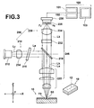
- FIG. 3 illustrates the schematic configuration of a confocal fluorescence microscope 200 and a controlling section 100 which are used for implementing the invention.
- the confocal fluorescence microscope 200 is used to identify the components contained in the biological sample R, and includes an excitation light applying section 210 to apply the excitation light Le and a fluorescence detection section 230 to detect a fluorescence intensity Ur of fluorescence Lk which is emitted when the excitation light Le is applied.
- the controlling section 100 carries out processing to remove the influence of fluorescence Lk0, which is emitted from the microchip 10 itself and acts as the background, from the fluorescence intensity Ur detected by the confocal fluorescence microscope 200, and includes a memory 101 to store values of a temporal change of the fluorescence intensity Ur detected by the fluorescence detection section 230, a CPU 102 to calculate fluorescence intensity Uc with reduced influence of the background from the detected fluorescence intensity Ur, and a monitor 103 that can display both the detected fluorescence intensity Ur and the fluorescence intensity Uc with reduced influence of the background.
- the memory 101 can store values of temporal changes of more than one detected fluorescence intensities Ur.
- the excitation light applying section 210 applies the excitation light Le to a substance to be detected, and includes: a laser light source 212 to emit laser light Lz; a collimator lens 214 to collimate the emitted laser light Lz; a wavelength filter 216 to block unnecessary wavelength components in the laser light Lz and transmit light components within the wavelength range of the excitation light Le; a dichroic mirror 218 to reflect the transmitted excitation light Le; and an object point-side collecting lens 222 to collect the reflected excitation light Le onto an object point-side focal point Fb.
- the excitation light Le used in this embodiment is red laser light having a wavelength of about 640 nm and an output power of about 10 mW.
- the dichroic mirror 218 reflects the excitation light Le and transmits the fluorescence Lk. It should be noted that the excitation light applying section 210 and the fluorescence detection section 230 share the same dichroic mirror 218 and object point-side collecting lens 222.
- the fluorescence detection section 230 detects the fluorescence Lk emitted from the substance to be detected when it is exposed to the excitation light Le, and includes: an object point-side collecting lens 222 to collect the fluorescence Lk emitted from the substance to be detected; a dichroic mirror 218 to transmit the fluorescence Lk outputted from the object point-side collecting lens 222 and reflect the excitation light Le; a noise light cut filter 232 to block noise light which is mixed in the transmitted fluorescence Lk; a pinhole plate 236 having a pinhole Ho formed therein; an image point-side collecting lens 234 to collect the fluorescence Lk, which has passed through the noise light cut filter 232, into the pinhole Ho formed in the pinhole plate 236; and a detector unit 238 to detect the fluorescence Lk, which has passed through the pinhole Ho.
- the fluorescence intensity Ur of the fluorescence Lk having a wavelength of about 677 nm is detected.
- the object point-side collecting lens 222 and the image point-side collecting lens 234 form an imaging optical system 246 for focusing an image of a point on the substance to be detected into the pinhole Ho.
- a point on the substance to be detected positioned at the object point-side focal point Fb and the pinhole Ho positioned at an image point-side focal point Fz are in a conjugate positional relationship relative to the imaging optical system 246.
- the microchip 10 is set on the confocal fluorescence microscope 200. At this time, the object point-side focal point Fb of the confocal fluorescence microscope 200 is positioned at the exposure area So in the micro flow channel 12 of the microchip 10.
- the excitation light Le is applied from the excitation light applying section 210 to the exposure area So.
- the fluorescence Lk emitted from the exposure area So in the micro flow channel 12, which is exposed to the excitation light Le, is directed to the fluorescence detection section 230.
- the fluorescence detection section 230 focuses the incoming fluorescence Lk into the pinhole Ho, and the fluorescence Lk passed through the pinhole Ho is detected by the detector unit 238.
- the shape of the image of the fluorescence Lk focused into the pinhole Ho conforms to the shape of the exposure area So.
- the component R1 and the component R2 By electrophoresing the biological sample R, as shown in FIG. 2 , the component R1 and the component R2, for example, move within the micro flow channel 12 toward the end portion 12b. Since the components R1 and R2 move at different rates, they are fed to the exposure area So in turn. As the components R1 and R2 are fed to the exposure area So, fluorescence rays Lk1 and Lk2 are emitted in turn from the components R1 and R2.
- the fluorescence Lk emitted from the biological sample R is detected at the fluorescence detection section 230.
- the fluorescence rays Lk1 and Lk2 emitted from the components R1 and R2 are detected in turn as fluorescence intensities Ur1 and Ur2.
- the detected fluorescence intensity Ur is stored in the memory 101 of the controlling section 100 over time, so that times T1 and T2 taken for the components R1 and R2 passing through the exposure area So, for example, can be obtained.
- the components contained in the biological sample R can be identified.
- the component R1 is a known component
- the component R2 can relatively be identified by dividing the fluorescence intensity Ur1 by the fluorescence intensity Ur2 with using the component R1 as a reference.
- microchip 10 may be identified by providing the microchip 10 with more than one micro flow channels 12 and letting different components flow through different flow channels.
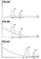
- FIGs. 4A to 4C show temporal changes of the detected fluorescence intensity Ur.
- the abscissa axis represents time T and the ordinate axis represents the fluorescence intensity Ur.
- FIG. 4A shows an ideal temporal change of the fluorescence intensity Ur. Since no fluorescence is emitted from the microchip 10 itself, the fluorescence Lk is emitted only from the biological sample R being electrophoresed. For example, the fluorescence intensities Ur1 and Ur2 of the fluorescence rays Lk1 and Lk2 emitted from the components R1 and R2 in the biological sample R are detected in turn at detection times T1 and T2 without addition of a fluorescence intensity Ur0 of fluorescence Lk0 emitted from the microchip 10 itself. Therefore, the components R1 and R2 can be identified with high accuracy based on the detected fluorescence intensities Ur1 and Ur2.
- FIG. 4B shows an actual temporal change of the fluorescence intensity Ur. Since the fluorescence Lk0 is emitted from the microchip 10 itself, the fluorescence intensity Ur0 is detected.
- the fluorescence intensity Ur0 acts as the background and to be added to the fluorescence intensity Ur.
- the fluorescence intensities Ur1 and Ur2 of the components R1 and R2 in the biological sample R are detected at the detection times T1 and T2 with being added to the fluorescence intensity Ur0 from the microchip 10 itself.
- FIG. 4C shows a temporal change of the fluorescence intensity Ur in prior art.
- a predetermined waiting time Tw is provided so that the components R1 and R2, for example, in the biological sample R are fed to the exposure area So after the fluorescence intensity Ur0 has sufficiently attenuated, to detect the fluorescence intensities Ur1 and Ur2 from the components R1 and R2 at the detection times T1 and T2.
- a waiting time Tw of about 300 seconds from the start of application of the excitation light is provided.
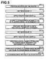
- FIG. 5 is a flow chart according to a first embodiment of the invention.
- the equivalent microchip 11 is set on the confocal fluorescence microscope 200 to be ready for detecting the fluorescence intensity Ur (ST1-2).
- the excitation light Le is applied to the equivalent microchip 11, and the fluorescence intensity Ur0 of the fluorescence Lk0 emitted from the equivalent microchip 11 itself exposed to the excitation light Le is detected (ST1-3).
- the detection is continued until the fluorescence intensity Ur0 sufficiently attenuates, and the temporal change of the fluorescence intensity Ur0 is stored in the memory 101 of the controlling section 100 (ST1-4).
- the microchip made of PMMA it is about 200 seconds from the start of application of the excitation light Le during which the fluorescence intensity Ur0 attenuates to about 20%, or preferably about 300 seconds from the start of application of the excitation light Le during which the fluorescence intensity Ur0 attenuates to about 10%.
- the fluorescence intensity Ur0 is stored for each equivalent microchip 11.
- the microchip 10 with the fluorescently-labeled biological sample R charged in the micro flow channel 12 thereof is prepared (ST1-5).
- the microchip 10 is set on the confocal fluorescence microscope 200 to be ready for detecting the fluorescence intensity Ur (ST1-6).
- the excitation light Le is applied to the microchip 10 with the fluorescently-labeled biological sample R charged in the micro flow channel 12 thereof, and the fluorescence intensity Ur0 of the fluorescence Lk0 emitted from the microchip 10 itself exposed to the excitation light Le is detected (ST1-7).
- the biological sample R is electrophoresed to be fed to the exposure area So (ST1-8).
- the components R1 and R2 are fed to the exposure area So.
- feed timing is about 20 seconds from the start of application of the excitation light Le during which the fluorescence intensity Ur0 attenuates to about 80%, or desirably about 40 seconds from the start of application of the excitation light Le during which the fluorescence intensity Ur0 attenuates to about 70%.
- Values of the temporal change of the fluorescence intensity Ur0 from the equivalent microchip 11 stored in the memory 101 of the controlling section 100 are read out, and the temporal change of the stored fluorescence intensity Ur0 is subtracted from the temporal change of the detected fluorescence intensity Ur (ST1-9). It should be noted that, in a case where values of temporal changes for more than one equivalent microchips 11 made of different materials are stored, values of the temporal change for one of the equivalent microchips 11 which is made of the same material as the microchip 10 used for identifying the components in the biological sample R may be selected and read out from the memory 101.
- the fluorescence intensity Uc with reduced influence of the fluorescence intensity Ur0 as the background is detected (ST1-10).
- fluorescence intensities Uc1 and Uc2 of the components R1 and R2 are detected.
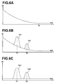
- FIGs. 6A to 6C show the effect of the first embodiment of the invention.
- the fluorescence Lk0 is emitted from the equivalent microchip 11 itself, and the fluorescence intensity Ur0 is detected.
- the fluorescence intensity Ur0 gradually attenuates, and sufficiently attenuates at a detection time Te. The temporal change during this attenuation is stored.
- the excitation light Le is applied to the microchip 10 with the fluorescently-labeled biological sample R charged in the micro flow channel 12 thereof, and the biological sample R is electrophoresed to detect the fluorescence intensity.
- the fluorescence intensity Ur0 of the fluorescence Lk0 emitted from the microchip 10 itself is detected, and then, the fluorescence intensities Ur1 and Ur2 from the components R1 and R2 in the biological sample R are detected at the detection times T1 and T2.
- the fluorescence intensity Uc with reduced influence of the background is detected with high accuracy in a shorter time.
- fluorescence intensities Uc1 and Uc2 of the components R1 and R2 in the biological sample R are detected. Further, it is not necessary to apply any additional treatment to the microchip 10.
- FIG. 7 is a flow chart according to a second embodiment of the invention.
- the microchip 10 with the fluorescently-labeled biological sample R charged in the micro flow channel 12 thereof is prepared (ST2-1).
- the microchip 10 is set on the confocal fluorescence microscope 200 to be ready for detecting the fluorescence intensity Ur (ST2-2).
- the excitation light Le is applied to the microchip 10 with the fluorescently-labeled biological sample R charged in the micro flow channel 12 thereof, and the fluorescence intensity Ur0 of the fluorescence Lk0 emitted from the microchip 10 itself exposed to the excitation light Le is detected (ST2-3).
- the fluorescence intensity Ur0 begins to attenuate and an initial temporal change of the fluorescence intensity Ur0 is detected. Based on the initial temporal change of the fluorescence intensity Ur0, the CPU 102 of the controlling section 100 estimates values of the temporal change of the fluorescence intensity Ur0 until it sufficiently attenuates (ST2-4). Specifically, in a case where the microchip made of PMMA is used in this embodiment, it is about 40 seconds from the start of application of the excitation light Le during which the fluorescence intensity Ur0 attenuates to about 70%, or desirably about 50 seconds from the start of application of the excitation light Le during which the fluorescence intensity Ur0 attenuates to about 60%.
- estimation method includes approximation by an exponential function, a power series, a logarithmic function or a fractional function. Approximation by an exponential function is desirable. Specific example of the estimation method further includes approximation achieved by preparing different types of microchips in advance, storing, for each microchip, a temporal change of the emitted fluorescence for the period from the start of application of the excitation light to the point at which the fluorescence intensity sufficiently attenuates, and selecting one of the stored temporal changes based on the initial temporal change of the fluorescence intensity Ur0.
- the biological sample R is electrophoresed to be fed to the exposure area So (ST2-5).
- the components R1 and R2 in the biological sample R are fed to the exposure area So.
- the temporal change of the estimated fluorescence intensity Ur0 is subtracted from the detected fluorescence intensity Ur (ST2-6).
- the fluorescence intensity Uc free of the influence of the fluorescence intensity Ur0 as the background is detected (ST2-7).
- the fluorescence intensities Uc1 and Uc2 of the components R1 and R2 in the biological sample R are detected.
- FIGs. 8A-8C show the effect of the second embodiment of the invention.
- the fluorescence Lk0 is emitted from the microchip 10 itself, and the fluorescence intensity Ur0 is detected.
- the fluorescence intensity Ur0 gradually attenuates. Based on the initial temporal change at the detection time Ti (the solid line in the drawing), the fluorescence intensity Ur until the detection time Te at which the fluorescence intensity of the fluorescence intensity Ur0 sufficiently attenuates is estimated (the dashed line in the drawing).
- the fluorescence intensities Ur1, Ur2 of the components R1 and R2 in the biological sample R are detected in turn.
- the fluorescence intensity Uc with reduced influence of the background is detected with high accuracy in a shorter time.
- the fluorescence intensities Uc1 and Uc2 of the components R1 and R2 in the biological sample R are detected. Further, it is not necessary to apply any additional treatment to the microchip 10.
Landscapes
- Health & Medical Sciences (AREA)
- Life Sciences & Earth Sciences (AREA)
- Chemical & Material Sciences (AREA)
- Physics & Mathematics (AREA)
- Immunology (AREA)
- Analytical Chemistry (AREA)
- Biochemistry (AREA)
- General Health & Medical Sciences (AREA)
- General Physics & Mathematics (AREA)
- Pathology (AREA)
- Nuclear Medicine, Radiotherapy & Molecular Imaging (AREA)
- Chemical Kinetics & Catalysis (AREA)
- Molecular Biology (AREA)
- Optics & Photonics (AREA)
- Spectroscopy & Molecular Physics (AREA)
- Electrochemistry (AREA)
- Investigating, Analyzing Materials By Fluorescence Or Luminescence (AREA)
Claims (8)
- Procédé de détection de fluorescence pour détecter une intensité de fluorescence (Ur) de la fluorescence (Lk) émise lorsqu'une lumière d'excitation (Le) est appliquée à une micropuce (10) avec un échantillon biologique marqué par fluorescence (R) chargé sur celle-ci, caractérisé en ce que le procédé comprend :la détection d'une intensité de fluorescence (Ur0) de la fluorescence (Lk0) émise par une micropuce équivalente (11) elle-même pendant une période du début d'application de la lumière d'excitation (Le) jusqu'à ce que l'intensité de fluorescence (Ur0) soit suffisamment atténuée, la micropuce équivalente (11) étant équivalente à la micropuce (10) ;le stockage d'un changement temporel de l'intensité de fluorescence détectée (Ur0) ;l'application de la lumière d'excitation (Le) à la micropuce (10) et le chargement de l'échantillon biologique (R) sur la micropuce (10) avant qu'une intensité de fluorescence (Ur0) de la fluorescence (Lk0) émise par la micropuce (10) elle-même soit suffisamment atténuée ;la détection de l'intensité de fluorescence (Ur) de la fluorescence (Lk) émise par la micropuce (10) pendant une période du début d'application de la lumière d'excitation (Le) à un temps après que l'échantillon biologique (R) ait été chargé sur la micropuce (10) ; etla soustraction, à l'intensité de fluorescence (Ur) détectée à partir de la micropuce (10) avec l'échantillon biologique (R) chargé sur celle-ci, de valeurs stockées de changement temporel d'intensité de fluorescence (Ur0) de la fluorescence (Lk0) émise par la micropuce équivalente (11) elle-même jusqu'à ce que l'intensité de fluorescence (Ur0) soit suffisamment atténuée, de manière à détecter une intensité de fluorescence (Uc) de la fluorescence (Lk) émise par l'échantillon biologique (R) exposé à la lumière d'excitation (Le).
- Procédé de détection de fluorescence selon la revendication 1, dans lequel les étapes de détection de l'intensité de fluorescence (Ur0) de la fluorescence (Lk0) émise par la micropuce équivalente (11) elle-même pendant la période du début d'application de la lumière d'excitation (Le) jusqu'à ce que l'intensité de fluorescence (Ur0) soit suffisamment atténuée et le stockage du changement temporel de l'intensité de fluorescence (Ur0) détectée sont conduites pour chacune de plusieurs micropuces (11) constituées de matériaux différents pour stocker différents types de changements temporels, et la soustraction est conduite avec la sélection d'un des différents types de changements temporels à utiliser pour la soustraction sur la base d'un matériau formant la micropuce (10) étant utilisé.
- Procédé de détection de fluorescence pour détecter une intensité de fluorescence (Ur) de la fluorescence (Lk) émise lorsque la lumière d'excitation (Le) est appliquée à une micropuce (10) avec un échantillon biologique marqué par fluorescence (R) chargé sur celle-ci, caractérisé en ce que le procédé comprend :l'application de la lumière d'excitation (Le) à la micropuce (10) et le chargement de l'échantillon biologique (R) sur la micropuce (10) avant qu'une intensité de fluorescence (Ur0) de la fluorescence (Lk0) émise par la micropuce (10) soit suffisamment atténuée ;la détection de l'intensité de fluorescence (Ur) de la fluorescence (Lk) émise par la micropuce (10) pendant une période du début d'application de la lumière d'excitation (Le) à un temps après que l'échantillon biologique (R) soit chargé sur la micropuce (10) ;l'estimation d'un changement temporel de l'intensité de fluorescence (Ur0) de la fluorescence (Lk0) émise par la micropuce (10) pendant une période jusqu'à ce que l'intensité de fluorescence (Ur0) soit suffisamment atténuée, sur la base d'un changement temporel initial de l'intensité de fluorescence (Ur0) de la fluorescence (Lk0) émise par la micropuce (10) obtenu par la détection ; etla soustraction, à l'intensité de fluorescence (Ur) détectée depuis la micropuce (10) avec l'échantillon biologique (R) chargé sur celle-ci, de valeurs du changement temporel estimé de l'intensité de fluorescence (Ur0) de la fluorescence (Lk0) émise par la micropuce (10) pendant la période jusqu'à ce que l'intensité de fluorescence (Ur0) soit suffisamment atténuée, de manière à détecter une intensité de fluorescence (Uc) de la fluorescence (Lk) émise par l'échantillon biologique (R) exposé à la lumière d'excitation (Le).
- Procédé de détection de fluorescence selon la revendication 3, dans lequel l'estimation du changement temporel est effectuée par approximation par une fonction exponentielle sur la base du changement temporel initial de l'intensité de fluorescence (Ur0) de la fluorescence (Lk0) émise par la micropuce (10).
- Procédé de détection de fluorescence selon la revendication 3, dans lequel l'estimation du changement temporel est effectuée par approximation par une série de puissance sur la base du changement temporel initial de l'intensité de fluorescence (Ur0) de la fluorescence (Lk0) émise par la micropuce (10).
- Procédé de détection de fluorescence selon la revendication 3, dans lequel l'estimation du changement temporel est effectuée par approximation par une fonction logarithmique sur la base du changement temporel initial de l'intensité de fluorescence (Ur0) de la fluorescence (Lk0) émise par la micropuce (10).
- Procédé de détection de fluorescence selon la revendication 3, dans lequel l'estimation du changement temporel est effectuée par approximation par une fonction fractionnaire sur la base du changement temporel initial de l'intensité de fluorescence (Ur0) de la fluorescence (Lk0) émise par la micropuce (10).
- Procédé de détection de fluorescence selon la revendication 3, dans lequel l'estimation du changement temporel est effectuée par sélection de l'un de différents types de changements temporels sur la base du changement temporel initial de l'intensité de fluorescence (Ur0) de la fluorescence (Lk0) émise par la micropuce (10), les différents types de changements temporels étant obtenus par détection d'une intensité de fluorescence (Ur0) de la fluorescence (Lk0) émise par chacun de différents types de micropuces (11) exposés à la lumière d'excitation (Le) pendant une période du début d'application de la lumière d'excitation (Le) jusqu'à ce que l'intensité de fluorescence (Ur0) soit suffisamment atténuée.
Applications Claiming Priority (2)
| Application Number | Priority Date | Filing Date | Title |
|---|---|---|---|
| JP2007255403A JP4993494B2 (ja) | 2007-09-28 | 2007-09-28 | 蛍光検出方法 |
| PCT/JP2008/002642 WO2009041032A1 (fr) | 2007-09-28 | 2008-09-24 | Procédé de détection par fluorescence |
Publications (3)
| Publication Number | Publication Date |
|---|---|
| EP2194372A1 EP2194372A1 (fr) | 2010-06-09 |
| EP2194372A4 EP2194372A4 (fr) | 2013-01-09 |
| EP2194372B1 true EP2194372B1 (fr) | 2013-11-06 |
Family
ID=40510937
Family Applications (1)
| Application Number | Title | Priority Date | Filing Date |
|---|---|---|---|
| EP08833299.4A Active EP2194372B1 (fr) | 2007-09-28 | 2008-09-24 | Procédé de détection par fluorescence |
Country Status (4)
| Country | Link |
|---|---|
| US (1) | US8283640B2 (fr) |
| EP (1) | EP2194372B1 (fr) |
| JP (1) | JP4993494B2 (fr) |
| WO (1) | WO2009041032A1 (fr) |
Families Citing this family (4)
| Publication number | Priority date | Publication date | Assignee | Title |
|---|---|---|---|---|
| CN103018218A (zh) * | 2011-11-10 | 2013-04-03 | 浙江理工大学 | 一种用于洗涤剂洗涤效果检测和评价的荧光分析方法 |
| EP3433017A4 (fr) * | 2016-03-25 | 2020-01-01 | Bioceryx Inc. | Appareils et procédés pour évaluer des nombres de séquences cibles |
| CN107748148A (zh) * | 2017-09-04 | 2018-03-02 | 江苏大学 | 基于石墨烯氧化物双氨基固定多t序列检测汞离子的方法 |
| JP7282307B2 (ja) * | 2019-05-20 | 2023-05-29 | 株式会社島津製作所 | 応力発光データ処理装置、応力発光データ処理方法、応力発光測定装置および応力発光試験システム |
Family Cites Families (7)
| Publication number | Priority date | Publication date | Assignee | Title |
|---|---|---|---|---|
| US6485625B1 (en) * | 1995-05-09 | 2002-11-26 | Curagen Corporation | Apparatus and method for the generation, separation, detection, and recognition of biopolymer fragments |
| US6333501B1 (en) * | 2000-01-27 | 2001-12-25 | Perkin-Elmer Corporation | Methods, apparatus, and articles of manufacture for performing spectral calibration |
| JP2002181708A (ja) * | 2000-12-14 | 2002-06-26 | Asahi Techno Glass Corp | マイクロアレイチップの読取方法及びその装置 |
| JP2003084002A (ja) * | 2001-06-27 | 2003-03-19 | Fuji Photo Film Co Ltd | 蛍光検出におけるバックグラウンドの低減方法 |
| JP4701739B2 (ja) * | 2005-02-17 | 2011-06-15 | パナソニック株式会社 | 蛍光測定装置 |
| JP4864519B2 (ja) * | 2006-04-11 | 2012-02-01 | 浜松ホトニクス株式会社 | 光測定装置、光測定方法、及び光測定プログラム |
| JP2008122297A (ja) * | 2006-11-14 | 2008-05-29 | Fujitsu Ltd | 蛍光検出装置および蛍光検出方法 |
-
2007
- 2007-09-28 JP JP2007255403A patent/JP4993494B2/ja active Active
-
2008
- 2008-09-24 EP EP08833299.4A patent/EP2194372B1/fr active Active
- 2008-09-24 WO PCT/JP2008/002642 patent/WO2009041032A1/fr not_active Ceased
- 2008-09-24 US US12/680,106 patent/US8283640B2/en active Active
Also Published As
| Publication number | Publication date |
|---|---|
| JP2009085756A (ja) | 2009-04-23 |
| EP2194372A1 (fr) | 2010-06-09 |
| EP2194372A4 (fr) | 2013-01-09 |
| WO2009041032A1 (fr) | 2009-04-02 |
| JP4993494B2 (ja) | 2012-08-08 |
| US20100258740A1 (en) | 2010-10-14 |
| US8283640B2 (en) | 2012-10-09 |
Similar Documents
| Publication | Publication Date | Title |
|---|---|---|
| CN102077080B (zh) | 微阵列表征系统和方法 | |
| EP2194372B1 (fr) | Procédé de détection par fluorescence | |
| WO2013177617A1 (fr) | Balayage bidirectionnel pour microscopie à luminescence | |
| WO2014188887A1 (fr) | Analyseur d'acides nucléiques et méthode d'analyse des acides nucléiques l'utilisant | |
| US20100068714A1 (en) | Multivariate detection of molecules in biossay | |
| EP2681540B1 (fr) | Appareil de détermination de substance | |
| JP4152054B2 (ja) | 画像読み取り装置 | |
| JP5903486B2 (ja) | 細胞環境内でのタンパク質−タンパク質相互作用分析方法及び装置 | |
| JP5867729B2 (ja) | 検体のパラメータを決定する方法及び装置 | |
| JP2002181708A (ja) | マイクロアレイチップの読取方法及びその装置 | |
| KR20220120516A (ko) | 열제어부가 통합된, turn-off 방식의 광신호 측정용 액적 로딩 카트리지 | |
| JP2009002774A (ja) | 生体物質検出装置 | |
| US20240241080A1 (en) | Using electrophoresis for disease detection based on controlled molecular charge | |
| EP2542900B1 (fr) | Appareil et procédé pour la détection et la mesure d'intéractions biomoléculaires | |
| EP1186886A2 (fr) | Méthode d'analyse biochimique et appareil pour utiliser cette méthode | |
| JP3761726B2 (ja) | マイクロアレイチップの読取方法および読取装置 | |
| WO2015045586A1 (fr) | Dispositif et procédé de détection de fluorescence | |
| JP2004144532A (ja) | キャピラリー泳動分取システム及び分取方法 | |
| US20230280338A1 (en) | Improvements in or relating to an apparatus for detection and analysis of a component | |
| JP2005030950A (ja) | 固定化された物質の定量方法 | |
| KR20190102361A (ko) | 형광시정수를 이용한 체외 진단방법 및 이를 위한 체외 진단시스템 | |
| WO2024227187A2 (fr) | Utilisation de l'électrophorèse pour la détection d'une maladie sur la base d'une charge moléculaire régulée | |
| JP4585429B2 (ja) | 蛍光検出装置の光検出手段保護方法および蛍光検出装置 | |
| EP4630811A1 (fr) | Détection à paramètres multiples dans un nanocanal | |
| WO2024246492A1 (fr) | Système de microscopie |
Legal Events
| Date | Code | Title | Description |
|---|---|---|---|
| PUAI | Public reference made under article 153(3) epc to a published international application that has entered the european phase |
Free format text: ORIGINAL CODE: 0009012 |
|
| 17P | Request for examination filed |
Effective date: 20100325 |
|
| AK | Designated contracting states |
Kind code of ref document: A1 Designated state(s): AT BE BG CH CY CZ DE DK EE ES FI FR GB GR HR HU IE IS IT LI LT LU LV MC MT NL NO PL PT RO SE SI SK TR |
|
| AX | Request for extension of the european patent |
Extension state: AL BA MK RS |
|
| DAX | Request for extension of the european patent (deleted) | ||
| A4 | Supplementary search report drawn up and despatched |
Effective date: 20121210 |
|
| RIC1 | Information provided on ipc code assigned before grant |
Ipc: G01N 27/447 20060101ALI20121204BHEP Ipc: G01N 21/64 20060101AFI20121204BHEP |
|
| GRAP | Despatch of communication of intention to grant a patent |
Free format text: ORIGINAL CODE: EPIDOSNIGR1 |
|
| INTG | Intention to grant announced |
Effective date: 20130517 |
|
| GRAS | Grant fee paid |
Free format text: ORIGINAL CODE: EPIDOSNIGR3 |
|
| GRAA | (expected) grant |
Free format text: ORIGINAL CODE: 0009210 |
|
| AK | Designated contracting states |
Kind code of ref document: B1 Designated state(s): AT BE BG CH CY CZ DE DK EE ES FI FR GB GR HR HU IE IS IT LI LT LU LV MC MT NL NO PL PT RO SE SI SK TR |
|
| REG | Reference to a national code |
Ref country code: GB Ref legal event code: FG4D |
|
| REG | Reference to a national code |
Ref country code: CH Ref legal event code: EP |
|
| REG | Reference to a national code |
Ref country code: AT Ref legal event code: REF Ref document number: 639806 Country of ref document: AT Kind code of ref document: T Effective date: 20131215 |
|
| REG | Reference to a national code |
Ref country code: IE Ref legal event code: FG4D |
|
| REG | Reference to a national code |
Ref country code: DE Ref legal event code: R096 Ref document number: 602008028643 Country of ref document: DE Effective date: 20140109 |
|
| REG | Reference to a national code |
Ref country code: NL Ref legal event code: VDEP Effective date: 20131106 |
|
| REG | Reference to a national code |
Ref country code: AT Ref legal event code: MK05 Ref document number: 639806 Country of ref document: AT Kind code of ref document: T Effective date: 20131106 |
|
| REG | Reference to a national code |
Ref country code: LT Ref legal event code: MG4D |
|
| PG25 | Lapsed in a contracting state [announced via postgrant information from national office to epo] |
Ref country code: FI Free format text: LAPSE BECAUSE OF FAILURE TO SUBMIT A TRANSLATION OF THE DESCRIPTION OR TO PAY THE FEE WITHIN THE PRESCRIBED TIME-LIMIT Effective date: 20131106 Ref country code: NL Free format text: LAPSE BECAUSE OF FAILURE TO SUBMIT A TRANSLATION OF THE DESCRIPTION OR TO PAY THE FEE WITHIN THE PRESCRIBED TIME-LIMIT Effective date: 20131106 Ref country code: HR Free format text: LAPSE BECAUSE OF FAILURE TO SUBMIT A TRANSLATION OF THE DESCRIPTION OR TO PAY THE FEE WITHIN THE PRESCRIBED TIME-LIMIT Effective date: 20131106 Ref country code: LT Free format text: LAPSE BECAUSE OF FAILURE TO SUBMIT A TRANSLATION OF THE DESCRIPTION OR TO PAY THE FEE WITHIN THE PRESCRIBED TIME-LIMIT Effective date: 20131106 Ref country code: NO Free format text: LAPSE BECAUSE OF FAILURE TO SUBMIT A TRANSLATION OF THE DESCRIPTION OR TO PAY THE FEE WITHIN THE PRESCRIBED TIME-LIMIT Effective date: 20140206 Ref country code: IS Free format text: LAPSE BECAUSE OF FAILURE TO SUBMIT A TRANSLATION OF THE DESCRIPTION OR TO PAY THE FEE WITHIN THE PRESCRIBED TIME-LIMIT Effective date: 20140306 Ref country code: SE Free format text: LAPSE BECAUSE OF FAILURE TO SUBMIT A TRANSLATION OF THE DESCRIPTION OR TO PAY THE FEE WITHIN THE PRESCRIBED TIME-LIMIT Effective date: 20131106 |
|
| PG25 | Lapsed in a contracting state [announced via postgrant information from national office to epo] |
Ref country code: BE Free format text: LAPSE BECAUSE OF FAILURE TO SUBMIT A TRANSLATION OF THE DESCRIPTION OR TO PAY THE FEE WITHIN THE PRESCRIBED TIME-LIMIT Effective date: 20131106 Ref country code: AT Free format text: LAPSE BECAUSE OF FAILURE TO SUBMIT A TRANSLATION OF THE DESCRIPTION OR TO PAY THE FEE WITHIN THE PRESCRIBED TIME-LIMIT Effective date: 20131106 Ref country code: LV Free format text: LAPSE BECAUSE OF FAILURE TO SUBMIT A TRANSLATION OF THE DESCRIPTION OR TO PAY THE FEE WITHIN THE PRESCRIBED TIME-LIMIT Effective date: 20131106 Ref country code: ES Free format text: LAPSE BECAUSE OF FAILURE TO SUBMIT A TRANSLATION OF THE DESCRIPTION OR TO PAY THE FEE WITHIN THE PRESCRIBED TIME-LIMIT Effective date: 20131106 |
|
| PG25 | Lapsed in a contracting state [announced via postgrant information from national office to epo] |
Ref country code: PT Free format text: LAPSE BECAUSE OF FAILURE TO SUBMIT A TRANSLATION OF THE DESCRIPTION OR TO PAY THE FEE WITHIN THE PRESCRIBED TIME-LIMIT Effective date: 20140306 |
|
| PG25 | Lapsed in a contracting state [announced via postgrant information from national office to epo] |
Ref country code: EE Free format text: LAPSE BECAUSE OF FAILURE TO SUBMIT A TRANSLATION OF THE DESCRIPTION OR TO PAY THE FEE WITHIN THE PRESCRIBED TIME-LIMIT Effective date: 20131106 |
|
| REG | Reference to a national code |
Ref country code: DE Ref legal event code: R097 Ref document number: 602008028643 Country of ref document: DE |
|
| PG25 | Lapsed in a contracting state [announced via postgrant information from national office to epo] |
Ref country code: SK Free format text: LAPSE BECAUSE OF FAILURE TO SUBMIT A TRANSLATION OF THE DESCRIPTION OR TO PAY THE FEE WITHIN THE PRESCRIBED TIME-LIMIT Effective date: 20131106 Ref country code: PL Free format text: LAPSE BECAUSE OF FAILURE TO SUBMIT A TRANSLATION OF THE DESCRIPTION OR TO PAY THE FEE WITHIN THE PRESCRIBED TIME-LIMIT Effective date: 20131106 Ref country code: CZ Free format text: LAPSE BECAUSE OF FAILURE TO SUBMIT A TRANSLATION OF THE DESCRIPTION OR TO PAY THE FEE WITHIN THE PRESCRIBED TIME-LIMIT Effective date: 20131106 Ref country code: IT Free format text: LAPSE BECAUSE OF FAILURE TO SUBMIT A TRANSLATION OF THE DESCRIPTION OR TO PAY THE FEE WITHIN THE PRESCRIBED TIME-LIMIT Effective date: 20131106 Ref country code: RO Free format text: LAPSE BECAUSE OF FAILURE TO SUBMIT A TRANSLATION OF THE DESCRIPTION OR TO PAY THE FEE WITHIN THE PRESCRIBED TIME-LIMIT Effective date: 20131106 |
|
| PLBE | No opposition filed within time limit |
Free format text: ORIGINAL CODE: 0009261 |
|
| STAA | Information on the status of an ep patent application or granted ep patent |
Free format text: STATUS: NO OPPOSITION FILED WITHIN TIME LIMIT |
|
| PG25 | Lapsed in a contracting state [announced via postgrant information from national office to epo] |
Ref country code: DK Free format text: LAPSE BECAUSE OF FAILURE TO SUBMIT A TRANSLATION OF THE DESCRIPTION OR TO PAY THE FEE WITHIN THE PRESCRIBED TIME-LIMIT Effective date: 20131106 |
|
| 26N | No opposition filed |
Effective date: 20140807 |
|
| REG | Reference to a national code |
Ref country code: DE Ref legal event code: R097 Ref document number: 602008028643 Country of ref document: DE Effective date: 20140807 |
|
| PG25 | Lapsed in a contracting state [announced via postgrant information from national office to epo] |
Ref country code: SI Free format text: LAPSE BECAUSE OF FAILURE TO SUBMIT A TRANSLATION OF THE DESCRIPTION OR TO PAY THE FEE WITHIN THE PRESCRIBED TIME-LIMIT Effective date: 20131106 |
|
| PG25 | Lapsed in a contracting state [announced via postgrant information from national office to epo] |
Ref country code: MC Free format text: LAPSE BECAUSE OF FAILURE TO SUBMIT A TRANSLATION OF THE DESCRIPTION OR TO PAY THE FEE WITHIN THE PRESCRIBED TIME-LIMIT Effective date: 20131106 Ref country code: LU Free format text: LAPSE BECAUSE OF FAILURE TO SUBMIT A TRANSLATION OF THE DESCRIPTION OR TO PAY THE FEE WITHIN THE PRESCRIBED TIME-LIMIT Effective date: 20140924 |
|
| REG | Reference to a national code |
Ref country code: CH Ref legal event code: PL |
|
| REG | Reference to a national code |
Ref country code: IE Ref legal event code: MM4A |
|
| PG25 | Lapsed in a contracting state [announced via postgrant information from national office to epo] |
Ref country code: CH Free format text: LAPSE BECAUSE OF NON-PAYMENT OF DUE FEES Effective date: 20140930 Ref country code: LI Free format text: LAPSE BECAUSE OF NON-PAYMENT OF DUE FEES Effective date: 20140930 |
|
| PG25 | Lapsed in a contracting state [announced via postgrant information from national office to epo] |
Ref country code: IE Free format text: LAPSE BECAUSE OF NON-PAYMENT OF DUE FEES Effective date: 20140924 |
|
| PG25 | Lapsed in a contracting state [announced via postgrant information from national office to epo] |
Ref country code: BG Free format text: LAPSE BECAUSE OF FAILURE TO SUBMIT A TRANSLATION OF THE DESCRIPTION OR TO PAY THE FEE WITHIN THE PRESCRIBED TIME-LIMIT Effective date: 20131106 |
|
| PG25 | Lapsed in a contracting state [announced via postgrant information from national office to epo] |
Ref country code: GR Free format text: LAPSE BECAUSE OF FAILURE TO SUBMIT A TRANSLATION OF THE DESCRIPTION OR TO PAY THE FEE WITHIN THE PRESCRIBED TIME-LIMIT Effective date: 20140207 Ref country code: MT Free format text: LAPSE BECAUSE OF FAILURE TO SUBMIT A TRANSLATION OF THE DESCRIPTION OR TO PAY THE FEE WITHIN THE PRESCRIBED TIME-LIMIT Effective date: 20131106 Ref country code: CY Free format text: LAPSE BECAUSE OF FAILURE TO SUBMIT A TRANSLATION OF THE DESCRIPTION OR TO PAY THE FEE WITHIN THE PRESCRIBED TIME-LIMIT Effective date: 20131106 |
|
| PG25 | Lapsed in a contracting state [announced via postgrant information from national office to epo] |
Ref country code: HU Free format text: LAPSE BECAUSE OF FAILURE TO SUBMIT A TRANSLATION OF THE DESCRIPTION OR TO PAY THE FEE WITHIN THE PRESCRIBED TIME-LIMIT; INVALID AB INITIO Effective date: 20080924 Ref country code: TR Free format text: LAPSE BECAUSE OF FAILURE TO SUBMIT A TRANSLATION OF THE DESCRIPTION OR TO PAY THE FEE WITHIN THE PRESCRIBED TIME-LIMIT Effective date: 20131106 |
|
| REG | Reference to a national code |
Ref country code: FR Ref legal event code: PLFP Year of fee payment: 9 |
|
| REG | Reference to a national code |
Ref country code: DE Ref legal event code: R082 Ref document number: 602008028643 Country of ref document: DE Representative=s name: KLUNKER IP PATENTANWAELTE PARTG MBB, DE |
|
| REG | Reference to a national code |
Ref country code: FR Ref legal event code: PLFP Year of fee payment: 10 |
|
| REG | Reference to a national code |
Ref country code: FR Ref legal event code: PLFP Year of fee payment: 11 |
|
| PGFP | Annual fee paid to national office [announced via postgrant information from national office to epo] |
Ref country code: GB Payment date: 20200916 Year of fee payment: 13 |
|
| GBPC | Gb: european patent ceased through non-payment of renewal fee |
Effective date: 20210924 |
|
| PG25 | Lapsed in a contracting state [announced via postgrant information from national office to epo] |
Ref country code: GB Free format text: LAPSE BECAUSE OF NON-PAYMENT OF DUE FEES Effective date: 20210924 |
|
| P01 | Opt-out of the competence of the unified patent court (upc) registered |
Effective date: 20230515 |
|
| PGFP | Annual fee paid to national office [announced via postgrant information from national office to epo] |
Ref country code: DE Payment date: 20240730 Year of fee payment: 17 |
|
| PGFP | Annual fee paid to national office [announced via postgrant information from national office to epo] |
Ref country code: FR Payment date: 20240808 Year of fee payment: 17 |