EP2194389B1 - Durchführungsdiagnose - Google Patents
Durchführungsdiagnose Download PDFInfo
- Publication number
- EP2194389B1 EP2194389B1 EP08170770A EP08170770A EP2194389B1 EP 2194389 B1 EP2194389 B1 EP 2194389B1 EP 08170770 A EP08170770 A EP 08170770A EP 08170770 A EP08170770 A EP 08170770A EP 2194389 B1 EP2194389 B1 EP 2194389B1
- Authority
- EP
- European Patent Office
- Prior art keywords
- temperature
- pressure
- bushing
- diagnosing
- insulating medium
- Prior art date
- Legal status (The legal status is an assumption and is not a legal conclusion. Google has not performed a legal analysis and makes no representation as to the accuracy of the status listed.)
- Active
Links
Images

Classifications
-
- H—ELECTRICITY
- H01—ELECTRIC ELEMENTS
- H01B—CABLES; CONDUCTORS; INSULATORS; SELECTION OF MATERIALS FOR THEIR CONDUCTIVE, INSULATING OR DIELECTRIC PROPERTIES
- H01B3/00—Insulators or insulating bodies characterised by the insulating materials; Selection of materials for their insulating or dielectric properties
- H01B3/18—Insulators or insulating bodies characterised by the insulating materials; Selection of materials for their insulating or dielectric properties mainly consisting of organic substances
- H01B3/20—Insulators or insulating bodies characterised by the insulating materials; Selection of materials for their insulating or dielectric properties mainly consisting of organic substances liquids, e.g. oils
-
- G—PHYSICS
- G05—CONTROLLING; REGULATING
- G05B—CONTROL OR REGULATING SYSTEMS IN GENERAL; FUNCTIONAL ELEMENTS OF SUCH SYSTEMS; MONITORING OR TESTING ARRANGEMENTS FOR SUCH SYSTEMS OR ELEMENTS
- G05B19/00—Program-control systems
- G05B19/02—Program-control systems electric
- G05B19/04—Program control other than numerical control, i.e. in sequence controllers or logic controllers
- G05B19/042—Program control other than numerical control, i.e. in sequence controllers or logic controllers using digital processors
- G05B19/0428—Safety, monitoring
-
- G—PHYSICS
- G01—MEASURING; TESTING
- G01R—MEASURING ELECTRIC VARIABLES; MEASURING MAGNETIC VARIABLES
- G01R31/00—Arrangements for testing electric properties; Arrangements for locating electric faults; Arrangements for electrical testing characterised by what is being tested not provided for elsewhere
- G01R31/12—Testing dielectric strength or breakdown voltage ; Testing or monitoring effectiveness or level of insulation, e.g. of a cable or of an apparatus, for example using partial discharge measurements; Electrostatic testing
-
- G—PHYSICS
- G01—MEASURING; TESTING
- G01R—MEASURING ELECTRIC VARIABLES; MEASURING MAGNETIC VARIABLES
- G01R31/00—Arrangements for testing electric properties; Arrangements for locating electric faults; Arrangements for electrical testing characterised by what is being tested not provided for elsewhere
- G01R31/50—Testing of electric apparatus, lines, cables or components for short-circuits, continuity, leakage current or incorrect line connections
- G01R31/62—Testing of transformers
-
- G—PHYSICS
- G05—CONTROLLING; REGULATING
- G05B—CONTROL OR REGULATING SYSTEMS IN GENERAL; FUNCTIONAL ELEMENTS OF SUCH SYSTEMS; MONITORING OR TESTING ARRANGEMENTS FOR SUCH SYSTEMS OR ELEMENTS
- G05B2219/00—Program-control systems
- G05B2219/20—Pc systems
- G05B2219/24—Pc safety
- G05B2219/24042—Signature analysis, compare recorded with current data, if error then alarm
Definitions
- the present invention relates to electrical apparatuses having sealed fluid based insulating systems, such as bushings for pieces of electrical high-voltage equipment, and more particularly to a method, device and computer program product for diagnosing the status of an electrical apparatus having a sealed fluid based insulating system.
- One type of electrical apparatus that has a sealed fluid based insulating system is an electrical property measuring and field controlling apparatus, which may be a bushing.
- Bushings may be provided for pieces of electrical high-voltage equipment and are known to carry current of high voltage through a zone of a different potential, which different potential is ground potential when the bushing is a transformer bushing. In order to avoid being a safety hazard, the bushing itself needs to be monitored regarding how well it is functioning.
- One way to perform this may be through opening the bushing and take samples of the fluid, for instance oil, which is used as an insulating medium inside the bushing.
- the temperature of this oil can then be measured and used for diagnosing the bushing.
- the amount of oil in the bushing may be changed and the oil may also become contaminated when opening the bushing. There is in this case also a risk that the bushing is not sealed properly after such taking of samples.
- US 2005/0223782 does for instance describe a transformer monitoring system.
- the current of the transformer and an ambient temperature are measured. These are used for determining an oil temperature of the transformer.
- the actual transformer oil temperature is then measured and compared with the determined oil temperature and an anomaly is determined if a temperature difference exceeds a threshold.
- the inner pressure of the transformer is determined and compared with a threshold and an anomaly is determined if this pressure exceeds a pressure threshold.
- US 2002/0161558 describes a transformer monitoring system. In the system a number of physical quantities are monitored, like current, top oil temperature and ambient temperature.
- US 4,654,806 describes a transformer monitoring system. In this system various parameters are measured, such as oil temperature, ambient temperature and pressure. These are then each compared with a corresponding threshold.
- EP 747 715 does for instance describe diagnosing the status of a bushing through measuring imbalance current waveforms from a number of bushings, comparing imbalance values with each other and initial values to determine if a threshold is exceeded. If the threshold is exceeded there is a determination being made about which of the bushings that have changed as well as the changes in capacitances and power values of these bushings. These changed capacitances and power values are then temperature compensated based on (transformer) top-oil and ambient temperatures. This document seems to require several bushings for performing diagnosing and furthermore only measures the current.
- the present invention is directed towards solving the problem of providing diagnosis that can be performed for a single electrical apparatus having a sealed fluid based insulating system without having to open this electrical apparatus.
- This problem is generally solved through determining a theoretical apparatus pressure based on received measurements of a current running through the apparatus, comparing received measurements of an actual apparatus pressure with the theoretical apparatus pressure and diagnosing the status of the apparatus based on the comparison.
- One object of the present invention is thus to provide a method for diagnosing the status of an electrical apparatus having a sealed fluid based insulating system, which can be performed for a single bushing without having to open this electrical apparatus.
- This object is according to the present invention solved through a method for diagnosing the status of an electrical apparatus having a sealed fluid based insulating system and comprising the steps of:
- Another object of the present invention is to provide a device for diagnosing the status of an electrical apparatus having a sealed fluid based insulating system, which can perform diagnosis for a single electrical apparatus without having to open this electrical apparatus.
- This object is according to another aspect of the present invention solved through a device for diagnosing the status of an electrical apparatus having a sealed fluid based insulating system comprising:
- a further object of the present invention is to provide a computer program product for diagnosing the status of an electrical apparatus having a sealed fluid based insulating system, which allows the diagnosis to be performed for a single electrical apparatus without having to open this electrical apparatus.
- This object is according to a further aspect of the present invention solved through a computer program product for diagnosing the status of an electrical apparatus having a sealed fluid based insulating system
- a computer program product for diagnosing the status of an electrical apparatus having a sealed fluid based insulating system
- computer program code provided on a data carrier for making a computer do, when said computer program code is loaded in the computer determine a corresponding theoretical apparatus pressure based on received measurements of a current running through the apparatus, receive measurements of an actual apparatus pressure, compare the actual apparatus pressure with the theoretical apparatus pressure, and diagnose the status of the apparatus based on the comparison.
- the present invention has a number of advantages. It allows diagnosing the status of a single electrical apparatus having a sealed fluid based insulating system without the electrical apparatus having to be opened for investigating the content of it. Such opening may negatively influence the comparison in that properties of insulating mediums used in the electrical apparatus may be changed, which may have a negative effect on the safety of the electrical apparatus. Also pollution and/or contaminants can enter the electrical apparatus. An opening may also lead to a re-closing not being performed properly. The electrical apparatus may become leaky. All these problems are avoided with the diagnosing of the present invention.
- the diagnosing can furthermore be performed in a very simple way with a limited number of further elements in addition to those that are normally used when diagnosing electrical apparatus and pieces of electrical high-voltage equipment, such as bushings and transformers.
- fig. 1 shows a schematic view of a device according to the present invention being connected to a bushing as well as to temperature sensors, where the bushing is in turn attached to a transformer
- fig. 2 shows a sectional view of the bushing
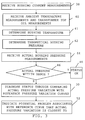
- fig. 3 shows a flow chart of a number of method steps being performed in a method for diagnosing the status of a bushing
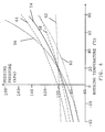
- fig. 4 shows a diagram with curves regarding pressure in relation to temperature and including a first curve representing a theoretical pressure and a set of reference curves representing potential problems for the bushing.
- a bushing is one such apparatus that is used for measuring electrical properties of pieces electrical high-voltage equipment, which pieces of equipment may be conductors, power lines and inductively operating elements such as transformers and reactors.
- the present invention is directed towards providing such diagnosis. This type of diagnosis is provided for determining if the electrical apparatus is functioning properly or not and to determine in what way it is faulty if not functioning properly.
- Fig. 1 schematically shows a device 10 for diagnosing the functioning of an electrical apparatus having a sealed fluid based insulating system.
- This electrical apparatus is here a bushing 14.
- the device 10 includes at least one input and here only one input 24, which is connected to two surrounding temperature sensors, an ambient temperature sensor 22 and an insulating medium temperature sensor of a piece of electrical high-voltage equipment that the bushing is attached to.
- the piece of equipment is a transformer 12 provided in a transformer tank and the insulating medium is transformer oil in this tank.
- This transformer 12 has a first and a second winding 16 and 18.
- the insulating medium temperature sensor is therefore here a top oil temperature sensor 20.
- the input 24 is also connected to a current sensor 23 for detecting the current running through the bushing 14. It also has one connection to the bushing 14 for receiving apparatus pressure measurements. As an alternative to using one input for several types of measurements, it is of course possible to use several inputs for the various measurements.
- the bushing 14 is attached to the transformer 12 and more particularly to the second winding 18 of the transformer 12. In the figure there is no bushing connected to the first winding 16. It should be realized that it is of course possible that a bushing is connected also to this first winding 16 either instead of or in addition to the bushing 14 being connected to the second winding 18.
- the input 24 is finally connected to a diagnosing unit 26 provided in the interior of the device 10, which unit 26 performs diagnosis of the electrical apparatus, i.e. diagnoses the health and functioning of the bushing.
- the sensors may also include or be connected to A/D converters for providing digitalized measurements to the device 10.
- a sectional view of one bushing 14 being provided in the transformer at a distance from the top oil sensor 20 and that can be used with the present invention is schematically shown in fig. 2 .
- the bushing 14 As the bushing 14 is attached to the transformer a part of it is surrounded by the transformer oil of the transformer. The temperature of this transformer oil is determined by the top oil temperature sensor 20, which is placed in the transformer tank.
- the bushing 14 here includes a sealed chamber.
- the chamber has an extension in a direction, which direction is vertical when the bushing is attached to the transformer. In this chamber there runs a central electrical conductor 28 along this vertical direction, which conductor 28 is provided for connection to the transformer.
- the conductor 28 thus extends out of two opposite vertical ends of the chamber for being connected to the transformer at one end and may at the other end be connected to a line or to another electrical apparatus, where the end that is to be connected to the transformer is the lower vertical end.
- insulation 30 or a condenser core surrounding the conductor 28, which lower region is the part of the chamber that faces the transformer.
- the insulation 30 is typically made of paper and has a voltage control normally provided by foils that encircle the conductor 28 in this lower region.
- the paper may be cellulose or synthetic.
- the first fluid insulating medium is here furthermore a liquid insulating medium 32, which liquid insulating medium is here transformer oil, which may be a vegetable oil.
- This first insulating medium 32 is here filled in the chamber to a level so that all the insulation 30 is covered, i.e. the insulation 30 is here soaked in the first insulating medium 32.
- a second fluid insulating medium 34 which is here a gas, typically air. It may be another gas though, such as nitrogen.
- the second insulating medium 34 may here be provided at an overpressure.
- the second insulating medium 34 here provides a compressible volume for taking up volume variations of the liquid first insulating medium 32.
- the volume occupied by the second gaseous insulating medium 34 is therefore normally much smaller than the volume occupied by the first insulating medium 32.
- the second gaseous insulating medium 34 is for this reason also denoted a gas cushion.
- the first liquid insulating medium 32 is furthermore degassed.
- the first insulating medium is thus saturated and in a steady state.
- the current sensor 23 may include a current transformer that is provided in the transformer tank and encircling the bushing 14. This current transfer is then magnetically connected to the conductor 28. These two latter sensors are furthermore connected to the input of the diagnosing device in fig. 1 .
- A/D converters for converting analog measurement values into digital format.
- fig. 3 shows a flow chart of a number of method steps being performed in a method for diagnosing the status of a transformer bushing as shown in fig. 1 and 2 .
- the method starts with measuring the current in the conductor 28 of the bushing 14. These measurements are supplied from the bushing 14 to the input 24 of the diagnosing device 10, from where they are forwarded to the diagnosing unit 26. In this way the diagnosing unit 26 receives measurements of the current running through the bushing, step 38.
- the ambient temperature sensor 22 senses the ambient temperature, i.e. the temperature in the area surrounding the transformer 12 and bushing 14, and forwards ambient temperature measurements to the input 24 of the diagnosing device 10, from where they are forwarded to the diagnosing unit 26. Ambient temperature may for instance be room temperature of about 20°C.
- the transformer top oil temperature sensor 20 senses the top oil temperature of the oil, i.e.
- the diagnosing unit 26 also receives ambient temperature measurements and transformer top oil measurements, step 40. Based on this data, the diagnosing unit 26 then determines a theoretical bushing pressure.
- the theoretical bushing pressure is determined based on the current in the conductor 28.
- the amount and variation of the current over time in the conductor 28 gives rise to heat, which is transferred to the insulation 30 and first insulating medium 32.
- the heat transfer is dependent on known properties of the insulation 30 and the first insulating medium 32.
- the ambient temperature and the top oil temperature of the transformer 12 it is then possible to determine the temperature of the first insulating medium 32, which temperature is considered to be the bushing temperature.
- the bushing temperature is thus determined based on a determination of the heat generated in the bushing by the current, step 41, and the heat transferred to the surrounding media. This change in temperature is furthermore normally a slow process.
- This temperature furthermore gives rise to an expansion of this first insulating medium 32, which leads to the volume in the chamber being occupied by the first insulating medium increasing. Since the chamber is sealed, this expansion also leads to the volume of the second insulating medium decreasing.
- the temperature of the second insulating medium 34 or the gas cushion is here determined. This temperature depends on the previously determined bushing temperature, the ambient temperature and the current running through the conductor. Based on the gas cushion temperature and volume it is then possible to determine the pressure of the gas cushion. This pressure is then combined with the pressure of the first insulating medium in order to obtain a theoretical bushing pressure. In this way the diagnosing unit 26 thus determines a theoretical pressure of the bushing, step 42. It is thus clear that the theoretical pressure has a dependence of the bushing temperature.
- the theoretical pressure may be determined based on a model of the change in pressure in the gas cushion and through that the bushing pressure in relation to bushing temperature.
- this change in pressure is determined based on the change in volume of the first insulating medium, which change in volume indirectly influences the theoretical pressure, since it causes a change in volume of the second insulating medium, which then influences the theoretical pressure.
- p x is the density of this medium.
- This density has a constant component ⁇ a and a temperature dependent component ⁇ b
- T x is the average first insulating temperature in the bushing. This temperature T x is calculated from the heat transfer to the surrounding media and the heat generated in the bushing due to thermal and dielectric losses.
- the pressure sensor 36 detects the actual pressure in the bushing 14.
- the actual pressure is thus detected simultaneously with the measuring of the above-mentioned current. Measurements of the actual pressure are supplied from the pressure sensor 36 to the input 24 of the diagnosing device 10, from which input they are then forwarded to the diagnosing unit 26. In this way the diagnosing unit 26 thus receives measurements of the corresponding actual pressure in the bushing, step 44.
- the detected actual pressure thus corresponds to the determined theoretical pressure and vice versa.
- the pressure measurements are furthermore correlated with the current measurements. Because of this it is possible to associate a determined theoretical pressure with a measured pressure and optionally also with a certain bushing temperature.
- the diagnosing unit 26 compares the corresponding detected and the theoretical pressures with each other and if the difference between these is within a predetermined range, step 46, which range can vary depending on the determined bushing temperature, the diagnosing unit diagnoses or determines that the bushing is functioning satisfactorily, i.e. that the status of the bushing 14 is ok, step 48.
- the diagnosing unit 26 diagnoses that the bushing has changed its original properties or is faulty. In some variations of the present invention, this may be all that is done in the diagnosing of the bushing. The diagnosing may thus only involve separating a faulty from a functioning bushing based on the comparison of actual and theoretical pressures. In a preferred embodiment of the present invention, the diagnosing unit 26 however continues when having determined that a bushing has changed its original properties or is faulty and further diagnoses the status of the bushing based on comparing the way the actual pressure varies with bushing temperature with the way a set of reference pressure curves vary with temperature, step 50.
- fig. 4 shows a diagram of pressure in relation to temperature including a first curve 54 representing the theoretical pressure and a set of reference curves 56 - 64 representing various potential problems for the bushing.
- the X-axis shows the temperature in °C
- the Y-axis shows the pressure in kPa.
- These exemplifying curves are furthermore provided for a first insulating medium volume of 100 dm 3 and a second insulating medium volume of 15 dm 3 at room temperature.
- the curves, except for one potential problem curve, furthermore here represent a simplified situation where the second insulating medium has not started to enter or be solved in or mixed with the first insulating medium.
- a curve 54 (shown as a solid line) of the theoretical pressure or how the pressure should vary in relation to temperature when the bushing is functioning normally. This curve thus represents a bushing that functions satisfactory.
- a first potential problem curve 56 (shown as a first dashed line) of how the pressure varies with temperature for a bushing including too much insulating medium, i.e. too much transformer oil.
- a second potential problem curve 58 (shown as a first dash-dotted line) for a bushing including too little insulating medium, i.e. too little transformer oil.
- third potential problem curve 60 shows how the pressure varies with temperature for a bushing where an oil sample has been taken at high temperature.
- fourth potential problem curve 62 shows how the pressure varies with temperature for a leaking bushing, i.e. a bushing which is not completely tight.
- fifth potential problem curve 64 shows how the bushing pressure varies with temperature for a bushing where gas has been formed in the oil or where there has been overheating. This last potential problem curve does therefore represent a situation where the second insulating medium has entered, been solved in or mixed with the first insulating medium.
- the pressure in the bushing 14 may vary in relation to temperature in different ways because of various types of errors. It may for instance vary in one way if there is too much oil in the chamber of the bushing 14 and vary in another way if there is too little oil in the bushing 14.
- these two potential problem curves 56 and 58 like the theoretical pressure curve 54, have the same pressure in one point, which point is here a pressure of 100 kPa at room temperature, but otherwise differ from each other and also have different slopes.
- the pressure variations are larger with too much oil as compared with too little oil.
- the third curve 60 and the fifth curve 64 essentially involve a shifting of the theoretical pressure curve 54 up or down along the Y-axis. This means that these potential problems can be determined through investigating the size and sign of the difference between the measured and theoretical pressures for various temperatures when the measured pressure does not coincide with the theoretical pressure at room temperature. If the measured pressure is larger than the theoretical pressure by more than a third threshold value then gassing or overheating is determined, while if the measured pressure is lower than the theoretical pressure by more than a fourth threshold value, then a determination is made that an oil sample at high temperate has been taken. This means that if the oil sample has been taken via medium 34 the overpressure has been released at a high temperature. In the same way the third curve 60 may also represent an oil sample taken at a low pressure.
- the diagnosing unit 26 can therefore diagnose the status of the bushing through comparing the actual pressure variation with reference pressure variation curves, step 50, and indicate a potential problem that is associated with the reference pressure variation curve that the actual pressure variation is closest to, step 52. This means that if the measured pressure variation is closer to one such potential problem curve than to the theoretical pressure curve and the other reference pressure variation curves, the potential problem associated with this curve is chosen and indicated.
- the diagnosing according to the principles of the present invention can furthermore be performed in a very simple way with a limited number of additional elements.
- Surrounding temperature sensors (like top oil and ambient temperature sensors) and current sensors are well known and widely used in relation to bushings for performing monitoring of transformers.
- the additional elements needed are mainly a pressure sensor in a bushing as well as some additional processing power for performing the diagnosis.
- a monitoring function such as a bushing monitoring function, may be included as an additional function for a transformer monitoring function that is in many cases already present in relation a transformer.
- the diagnosing device may be provided as a computer where the input unit can be realized as a network interface such as a LAN interface and the diagnosing unit may be provided in the form of a processor with an associated program memory including computer program code that performs the diagnosing function of the invention when being run by the processor.
- the computer program code can then also be provided on a data carrier, such as memory stick or a CD ROM disc which code performs the diagnosing according to the present invention when the carrier is loaded into a computer.
- a data carrier such as memory stick or a CD ROM disc which code performs the diagnosing according to the present invention when the carrier is loaded into a computer.
- the present invention can be varied in many ways in addition to those already described.
- the bushing may be provided without insulation or condenser core.
- There may furthermore only be one insulating medium in the bushing, which may then be a gas, such as for instance SF6 or nitrogen.
- a gas such as for instance SF6 or nitrogen.
- the raised temperature of this medium that is the bushing temperature and also the bushing pressure used is the pressure of this medium.
- the model of the change in pressure that is used is then not depending on any change in volume, but only on the change in bushing temperature.
- the pressure sensor may furthermore have an alternative placing in that it is placed at the top of the chamber where the gas cushion is provided. If this placing is combined with a liquid first insulating medium and a second gaseous insulating medium it is possible that the theoretical and actual bushing pressures used are only based on the pressures of the second insulating medium.
- the described model of the theoretical pressure can of course be changed or adapted for taking account of gassing, i.e. that some of the second gaseous insulating medium does get mixed into the liquid first insulating medium.
- the pressure sensor of the bushing as well as the bushing may in some embodiments of the present invention be elements that are a part of the diagnosing device. Also one or both of the temperature sensors may be such elements. It may also be possible to determine the theoretical bushing pressure and bushing temperature without measuring ambient and transformer top oil temperatures.
- Diagnosing is not limited to inductively operating pieces of high-voltage equipment, like transformers and reactors, but can be used on any piece of high-voltage equipment that is sealed and has a thermally expandable insulation medium.
- the invention can furthermore be varied in that more than one bushing may be provided for a piece of equipment, like for instance three bushings, one for each phase of a power transmission system.
- more than one bushing may be provided for a piece of equipment, like for instance three bushings, one for each phase of a power transmission system.
- the bushing may furthermore not be directly connected to a piece of electrical equipment. It may first run through a wall and then be connected to the piece of equipment.
- the electrical apparatus is in fact not limited to bushings, but may be any electrical apparatus having a sealed fluid based insulating system and can therefore for instance also be a transformer or a reactor.
Landscapes
- Physics & Mathematics (AREA)
- General Physics & Mathematics (AREA)
- Engineering & Computer Science (AREA)
- Automation & Control Theory (AREA)
- Oil, Petroleum & Natural Gas (AREA)
- Chemical & Material Sciences (AREA)
- Power Engineering (AREA)
- Spectroscopy & Molecular Physics (AREA)
- Housings And Mounting Of Transformers (AREA)
- Testing Of Short-Circuits, Discontinuities, Leakage, Or Incorrect Line Connections (AREA)
- Testing Of Devices, Machine Parts, Or Other Structures Thereof (AREA)
- Glass Compositions (AREA)
- Cable Accessories (AREA)
- Measurement Of Radiation (AREA)
Claims (19)
- Verfahren zum Diagnostizieren des Zustands eines elektrischen Apparats, der ein versiegeltes, fluidbasiertes Isoliersystem (14) aufweist, wobei das Verfahren die Schritte umfasst:Empfangen (38) von Messungen eines Stroms, der durch den Apparat fließt,Bestimmen (42) eines theoretischen Apparatefluiddrucks basierend auf dem gemessenen Strom,Empfangen (44) von Messungen eines entsprechenden tatsächlichen Apparatefluiddrucks,Vergleichen (46) des tatsächlichen Apparatefluiddrucks mit dem theoretischen Apparatefluiddruck undDiagnostizieren (48, 50) des Zustands des Apparats basierend auf dem Vergleich.
- Verfahren nach Anspruch 1, welches weiter den Schritt umfasst: Bestimmen (41) einer Apparatetemperatur basierend auf dem gemessenen Strom, wobei der theoretische Fluiddruck basierend auf dieser Apparatetemperatur bestimmt wird.
- Verfahren nach Anspruch 2, welches weiter den Schritt umfasst: Empfangen von Umgebungstemperaturmessungen, wobei das Bestimmen der Apparatetemperatur basierend auf dem gemessenen Strom und den Umgebungstemperaturmessungen gemacht wird.
- Verfahren nach Anspruch 3, wobei der elektrische Apparat mit einem Stück von elektrischer Hochspannungsgerätschaft (12) verbunden ist und die Umgebungstemperaturmessungen Raumtemperaturmessungen und Messungen einer Isoliermediumstemperatur des Stücks von elektrischer Gerätschaft umfassen.
- Verfahren nach einem der Ansprüche 2 - 4, wobei die bestimmte Apparatetemperatur auf der Bestimmung der Wärme basiert ist, die in dem Apparat durch den Strom erzeugt wird.
- Verfahren nach einem der Ansprüche 2 - 5, wobei die Apparatetemperatur die Temperatur eines Isoliermediums (32) in dem Apparat ist.
- Verfahren nach einem der Ansprüche 2 - 6, wobei der theoretische Fluiddruck basierend auf einem Modell der Veränderung in dem Fluiddruck in dem Apparat im Verhältnis zu der Apparatetemperatur bestimmt wird.
- Verfahren nach einem der vorhergehenden Ansprüche, wobei der Schritt des Diagnostizierens umfasst: Vergleichen (48) der Art, in der der tatsächliche Fluiddruck mit der Temperatur variiert, mit der Art, in der ein Satz von Referenzdruckvariationskurven (56, 58, 60, 62, 64) mit der Temperatur variiert, wobei jede Referenzdruckvariationskurve mit einem entsprechenden potentiellen Problem assoziiert ist.
- Verfahren nach Anspruch 8, wobei der Satz von Referenzdruckvariationen mindestens eine Variation umfasst, die einen Indikator bereitstellt in der Gruppe von:nicht genug Isoliermedium,zu viel Isoliermedium,Apparateleck,Gasen oder Überhitzen,eine genommene Isoliermediumsprobe, undfehlerhafte elektrische Verbindung.
- Gerät (10) zum Diagnostizieren des Zustands eines elektrischen Apparats, der ein versiegeltes, fluidbasiertes Isoliersystem (14) aufweist, wobei das Gerät umfasst:mindestens einen Eingang (24) zum Empfangen von Messungen eines Stroms, der durch den Apparat fließt, und Messungen eines tatsächlichen Apparatefluiddrucks, wobei das Gerät gekennzeichnet ist durcheine Diagnoseeinheit (26), die eingerichtet ist,einen entsprechenden theoretischen Apparatefluiddruck basierend auf dem gemessenen Strom zu bestimmen,den tatsächlichen Apparatefluiddruck mit dem theoretischen Apparatefluiddruck zu vergleichen undden Zustand des Apparats basierend auf dem Vergleich zu bestimmen.
- Das Gerät nach Anspruch 10, wobei die Diagnoseeinheit (26) eingerichtet ist, eine Apparatetemperatur basierend auf dem gemessenen Strom zu bestimmen und den theoretischen Fluiddruck basierend auf dieser Apparatetemperatur zu bestimmen.
- Das Gerät nach Anspruch 11, wobei der mindestens eine Eingang (24) eingerichtet ist, mit mindestens einem Umgebungstemperatursensor (20, 22) verbunden zu werden, um Umgebungstemperaturmessungen zu empfangen, und wobei die Diagnoseeinheit (26) eingerichtet ist, die Apparatetemperatur basierend auf dem gemessenen Strom und den Umgebungstemperaturmessungen zu bestimmen.
- Das Gerät nach Anspruch 12, wobei der elektrische Apparat eingerichtet ist, mit einem Stück (12) einer elektrischen Hochspannungsgerätschaft verbunden zu werden, wobei der mindestens eine Umgebungstemperatursensor einen Raumtemperatursensor (22) und einen Isoliermediumstemperatursensor (20) in dem Stück von elektrischer Gerätschaft umfasst.
- Das Gerät nach einem der Ansprüche 11 - 13, wobei die bestimmte Apparatetemperatur auf der Bestimmung der Wärme basiert ist, die in dem Apparat durch den Strom erzeugt wird.
- Das Gerät nach einem der Ansprüche 11 - 14, wobei die Apparatetemperatur die Temperatur eines Isoliermediums in dem Apparat ist.
- Das Gerät nach einem der Ansprüche 11 - 15, wobei die Diagnoseeinheit eingerichtet ist, den theoretischen Fluiddruck basierend auf einem Modell der Veränderung im Druck im Verhältnis zur Apparatetemperatur zu bestimmen.
- Das Gerät nach einem der Ansprüche 10-16, wobei die Diagnoseeinheit, wenn sie zum Diagnostizieren des Zustands des Apparats angeordnet ist, eingerichtet ist, die Art, in der der tatsächliche Fluiddruck mit der Temperatur variiert, mit der Art zu vergleichen, in der ein Satz von Referenzdruckvariationskurven (56, 58, 60, 62, 64) mit der Temperatur variiert, wobei jede Referenzdruckvariation mit einem entsprechenden potentiellen Problem assoziiert ist.
- Das Gerät nach Anspruch 17, wobei der Satz von Referenzdruckvariationen mindestens eine Variation umfasst, die einen Indikator bereitstellt in der Gruppe von:nicht genug Isoliermedium,zu viel Isoliermedium,Apparateleck,Gasen oder Überhitzen,eine genommene Isoliermediumsprobe, undfehlerhafte elektrische Verbindung.
- Ein Computerprogrammprodukt zum Diagnostizieren des Zustands eines elektrischen Apparats, der ein versiegeltes, fluidbasiertes Isoliersystem aufweist, umfassend
Computerprogrammcode, der auf einem Datenträger bereitgestellt ist, um einen Computer zu veranlassen, die Verfahrensschritte von Anspruch 1 auszuführen, wenn der Computerprogrammcode in den Computer geladen wird.
Priority Applications (8)
| Application Number | Priority Date | Filing Date | Title |
|---|---|---|---|
| EP08170770A EP2194389B1 (de) | 2008-12-05 | 2008-12-05 | Durchführungsdiagnose |
| AT08170770T ATE504843T1 (de) | 2008-12-05 | 2008-12-05 | Durchführungsdiagnose |
| DE602008006101T DE602008006101D1 (de) | 2008-12-05 | 2008-12-05 | Durchführungsdiagnose |
| CN200980148853.7A CN102239416B (zh) | 2008-12-05 | 2009-10-28 | 套管诊断 |
| PCT/EP2009/064208 WO2010063519A1 (en) | 2008-12-05 | 2009-10-28 | Bushing diagnosis |
| KR1020117015384A KR101512877B1 (ko) | 2008-12-05 | 2009-10-28 | 밀봉 유체 기반 절연 시스템을 갖는 전기 장치의 상태를 진단하는 디바이스 및 방법 |
| BRPI0922285A BRPI0922285B8 (pt) | 2008-12-05 | 2009-10-28 | Método e dispositivo para diagnosticar o estado de um aparelho elétrico dotado de um sistema selado de isolamento baseado em fluido |
| US13/154,029 US9128477B2 (en) | 2008-12-05 | 2011-06-06 | Bushing diagnosis |
Applications Claiming Priority (1)
| Application Number | Priority Date | Filing Date | Title |
|---|---|---|---|
| EP08170770A EP2194389B1 (de) | 2008-12-05 | 2008-12-05 | Durchführungsdiagnose |
Publications (2)
| Publication Number | Publication Date |
|---|---|
| EP2194389A1 EP2194389A1 (de) | 2010-06-09 |
| EP2194389B1 true EP2194389B1 (de) | 2011-04-06 |
Family
ID=40718976
Family Applications (1)
| Application Number | Title | Priority Date | Filing Date |
|---|---|---|---|
| EP08170770A Active EP2194389B1 (de) | 2008-12-05 | 2008-12-05 | Durchführungsdiagnose |
Country Status (8)
| Country | Link |
|---|---|
| US (1) | US9128477B2 (de) |
| EP (1) | EP2194389B1 (de) |
| KR (1) | KR101512877B1 (de) |
| CN (1) | CN102239416B (de) |
| AT (1) | ATE504843T1 (de) |
| BR (1) | BRPI0922285B8 (de) |
| DE (1) | DE602008006101D1 (de) |
| WO (1) | WO2010063519A1 (de) |
Families Citing this family (16)
| Publication number | Priority date | Publication date | Assignee | Title |
|---|---|---|---|---|
| US8391938B2 (en) * | 2011-06-15 | 2013-03-05 | Electric Power Research Institute, Inc. | Transportable rapid deployment superconducting transformer |
| CN103278716B (zh) * | 2013-05-22 | 2015-10-28 | 中国南方电网有限责任公司超高压输电公司检修试验中心 | 一种直流输电换流变网侧套管的可靠性检测系统及方法 |
| EP3070483B1 (de) * | 2015-03-17 | 2017-09-13 | ABB Schweiz AG | Verfahren zur überwachung von transformatorbuchsen und system dafür |
| EP3206041A1 (de) * | 2016-08-16 | 2017-08-16 | ABB Schweiz AG | System und verfahren zur überwachung von transformatordurchführungen |
| CN106526372A (zh) * | 2016-10-27 | 2017-03-22 | 成都亚联科科技有限公司 | 一种变压器功能特性自动检测装置 |
| CN107066799B (zh) * | 2017-01-03 | 2021-03-12 | 国网上海市电力公司 | 一种地下变电站分体式冷却变压器热点温度计算方法 |
| EP3370073B1 (de) * | 2017-03-01 | 2020-04-29 | ABB Power Grids Switzerland AG | Verfahren und vorrichtung zur bestimmung der parameter kapazitiver komponenten |
| CA3055933A1 (en) * | 2017-03-10 | 2018-09-13 | Abb Schweiz Ag | Smart grid distribution transformer |
| WO2020160590A1 (en) * | 2019-02-05 | 2020-08-13 | Aurtra Pty Ltd | A sensor for transformer condition assessment |
| EP3702746B1 (de) * | 2019-03-01 | 2023-08-09 | Hitachi Energy Switzerland AG | Hochspannungsanlage mit einer vorrichtung zur bestimmung der temperaturverteilung |
| CN110504092B (zh) * | 2019-09-10 | 2022-03-08 | 日立能源瑞士股份公司 | 套管及其制造方法 |
| EP3828562B1 (de) * | 2019-11-28 | 2025-01-01 | Hitachi Energy Ltd | Intelligente elektrische durchführung mit integriertem sensor |
| CN112179639B (zh) * | 2020-09-29 | 2022-08-30 | 国网四川省电力公司电力科学研究院 | 变压器套管的非电气量缺陷判断方法、系统和介质 |
| CN114818159B (zh) * | 2021-09-27 | 2024-11-26 | 内蒙古电力(集团)有限责任公司内蒙古超高压供电局 | 一种油纸绝缘套管的取油口压力计算方法和装置 |
| CN116451450B (zh) * | 2023-03-31 | 2025-12-16 | 国网新疆电力有限公司电力科学研究院 | 基于数据拟合的变电站充油设备故障预警方法及装置 |
| CN117129133B (zh) * | 2023-10-27 | 2024-01-02 | 南京中鑫智电科技有限公司 | 一种用于高压套管压力的在线监测方法及系统 |
Family Cites Families (12)
| Publication number | Priority date | Publication date | Assignee | Title |
|---|---|---|---|---|
| US4019007A (en) * | 1975-09-25 | 1977-04-19 | Westinghouse Electric Corporation | Grounded-tank high-power compressed-gas circuit-interrupter |
| US4654806A (en) | 1984-03-30 | 1987-03-31 | Westinghouse Electric Corp. | Method and apparatus for monitoring transformers |
| JPH06162848A (ja) * | 1992-11-24 | 1994-06-10 | Ngk Insulators Ltd | 異常検出装置付きブッシング |
| US6177803B1 (en) | 1995-06-07 | 2001-01-23 | Doble Engineering Company | Monitoring elements in a multi-phase alternating current network |
| US5657510A (en) * | 1995-06-14 | 1997-08-19 | Yamashita Rubber Kabushiki Kaisha | Fluid-filled insulating bushing |
| US5736915A (en) * | 1995-12-21 | 1998-04-07 | Cooper Industries, Inc. | Hermetically sealed, non-venting electrical apparatus with dielectric fluid having defined chemical composition |
| EP0783198B1 (de) * | 1996-01-05 | 1998-09-16 | Jürgen Bastian | Überwachung der Spaltgasbildung in Transformatoren |
| US6853528B2 (en) * | 2002-03-14 | 2005-02-08 | Hitachi, Ltd. | Gas insulating apparatus and method for locating fault point thereof |
| WO2002048730A1 (en) * | 2000-12-15 | 2002-06-20 | Abb T&D Technology Ltd. | Tap changer condition diagnosing |
| US6906630B2 (en) | 2001-02-28 | 2005-06-14 | General Electric Company | Transformer management system and method |
| JP2005302794A (ja) | 2004-04-07 | 2005-10-27 | Hitachi Industrial Equipment Systems Co Ltd | 変圧器監視システム |
| CN100570262C (zh) * | 2006-03-21 | 2009-12-16 | 北京瑞恒超高压电器研究所 | 一种复合热管载流体 |
-
2008
- 2008-12-05 AT AT08170770T patent/ATE504843T1/de not_active IP Right Cessation
- 2008-12-05 DE DE602008006101T patent/DE602008006101D1/de active Active
- 2008-12-05 EP EP08170770A patent/EP2194389B1/de active Active
-
2009
- 2009-10-28 BR BRPI0922285A patent/BRPI0922285B8/pt active IP Right Grant
- 2009-10-28 CN CN200980148853.7A patent/CN102239416B/zh active Active
- 2009-10-28 WO PCT/EP2009/064208 patent/WO2010063519A1/en not_active Ceased
- 2009-10-28 KR KR1020117015384A patent/KR101512877B1/ko not_active Expired - Fee Related
-
2011
- 2011-06-06 US US13/154,029 patent/US9128477B2/en active Active
Also Published As
| Publication number | Publication date |
|---|---|
| BRPI0922285A2 (pt) | 2020-09-01 |
| WO2010063519A1 (en) | 2010-06-10 |
| EP2194389A1 (de) | 2010-06-09 |
| ATE504843T1 (de) | 2011-04-15 |
| CN102239416A (zh) | 2011-11-09 |
| KR20110108343A (ko) | 2011-10-05 |
| CN102239416B (zh) | 2015-02-25 |
| US20110301880A1 (en) | 2011-12-08 |
| US9128477B2 (en) | 2015-09-08 |
| BRPI0922285B8 (pt) | 2022-12-13 |
| DE602008006101D1 (de) | 2011-05-19 |
| KR101512877B1 (ko) | 2015-04-16 |
| BRPI0922285B1 (pt) | 2021-01-12 |
Similar Documents
| Publication | Publication Date | Title |
|---|---|---|
| US9128477B2 (en) | Bushing diagnosis | |
| CA2370174C (en) | Status detection apparatus and method for fluid-filled electrical equipment | |
| DE60031615T2 (de) | Intelligente Vorrichtung und Verfahren zur Analyse einer flüssigkeitsgefüllten elektrischen Anlage | |
| EP1085635A2 (de) | System und Methode zur intelligenten Analyse einer elektrischen flüssigkeitsgefüllten Vorrichtung | |
| KR101474052B1 (ko) | 절연액으로 채워진 전기 장치의 상대 습도를 판정하는 방법 및 장치 | |
| CN103748438B (zh) | 组合式氢与压力传感器组件 | |
| CN103765167B (zh) | 氢气和压力传感器的组合 | |
| CN102713605A (zh) | 用于推导电绝缘油中所溶解气体的浓度的方法和设备 | |
| CN115014658A (zh) | 一种油浸式变压器漏油监测方法及装置 | |
| Wang et al. | Top‐oil temperature modelling by calibrating oil time constant for an oil natural air natural distribution transformer | |
| JP2009168571A (ja) | 油入変圧器の劣化診断方法 | |
| WO2003075294A1 (en) | On-line detection and measurement system for gases in oil-filled electrical equipment | |
| CN102384968A (zh) | 用于评价变压器油使用寿命的试验装置 | |
| EP4394815A1 (de) | Diagnosesystem für transformator | |
| CN116451450B (zh) | 基于数据拟合的变电站充油设备故障预警方法及装置 | |
| JPS61150305A (ja) | 油入電器の寿命診断装置 | |
| Yu et al. | A Quantitative Assessment Method for Transformer Overheating Fault Severity Based on Weighted Carbon-Hydrogen Ratio of Characteristic Gases | |
| Sparling et al. | Experiences with continuous on-line monitoring of developing fault conditions in large power transformers | |
| MXPA01001693A (en) | Method and system of intelligent analysis for electrical | |
| MXPA01001695A (en) | Method and system of intelligent analysis for electrical |
Legal Events
| Date | Code | Title | Description |
|---|---|---|---|
| PUAI | Public reference made under article 153(3) epc to a published international application that has entered the european phase |
Free format text: ORIGINAL CODE: 0009012 |
|
| 17P | Request for examination filed |
Effective date: 20081205 |
|
| AK | Designated contracting states |
Kind code of ref document: A1 Designated state(s): AT BE BG CH CY CZ DE DK EE ES FI FR GB GR HR HU IE IS IT LI LT LU LV MC MT NL NO PL PT RO SE SI SK TR |
|
| AX | Request for extension of the european patent |
Extension state: AL BA MK RS |
|
| GRAP | Despatch of communication of intention to grant a patent |
Free format text: ORIGINAL CODE: EPIDOSNIGR1 |
|
| RIN1 | Information on inventor provided before grant (corrected) |
Inventor name: STENESTAM, BENGT-OLOF |
|
| AKX | Designation fees paid |
Designated state(s): AT BE BG CH CY CZ DE DK EE ES FI FR GB GR HR HU IE IS IT LI LT LU LV MC MT NL NO PL PT RO SE SI SK TR |
|
| GRAS | Grant fee paid |
Free format text: ORIGINAL CODE: EPIDOSNIGR3 |
|
| GRAA | (expected) grant |
Free format text: ORIGINAL CODE: 0009210 |
|
| AK | Designated contracting states |
Kind code of ref document: B1 Designated state(s): AT BE BG CH CY CZ DE DK EE ES FI FR GB GR HR HU IE IS IT LI LT LU LV MC MT NL NO PL PT RO SE SI SK TR |
|
| REG | Reference to a national code |
Ref country code: GB Ref legal event code: FG4D |
|
| REG | Reference to a national code |
Ref country code: CH Ref legal event code: EP |
|
| REG | Reference to a national code |
Ref country code: IE Ref legal event code: FG4D |
|
| REF | Corresponds to: |
Ref document number: 602008006101 Country of ref document: DE Date of ref document: 20110519 Kind code of ref document: P |
|
| REG | Reference to a national code |
Ref country code: DE Ref legal event code: R096 Ref document number: 602008006101 Country of ref document: DE Effective date: 20110519 |
|
| REG | Reference to a national code |
Ref country code: SE Ref legal event code: TRGR |
|
| REG | Reference to a national code |
Ref country code: NL Ref legal event code: VDEP Effective date: 20110406 |
|
| PG25 | Lapsed in a contracting state [announced via postgrant information from national office to epo] |
Ref country code: SI Free format text: LAPSE BECAUSE OF FAILURE TO SUBMIT A TRANSLATION OF THE DESCRIPTION OR TO PAY THE FEE WITHIN THE PRESCRIBED TIME-LIMIT Effective date: 20110406 |
|
| LTIE | Lt: invalidation of european patent or patent extension |
Effective date: 20110406 |
|
| PG25 | Lapsed in a contracting state [announced via postgrant information from national office to epo] |
Ref country code: PT Free format text: LAPSE BECAUSE OF FAILURE TO SUBMIT A TRANSLATION OF THE DESCRIPTION OR TO PAY THE FEE WITHIN THE PRESCRIBED TIME-LIMIT Effective date: 20110808 Ref country code: LT Free format text: LAPSE BECAUSE OF FAILURE TO SUBMIT A TRANSLATION OF THE DESCRIPTION OR TO PAY THE FEE WITHIN THE PRESCRIBED TIME-LIMIT Effective date: 20110406 Ref country code: HR Free format text: LAPSE BECAUSE OF FAILURE TO SUBMIT A TRANSLATION OF THE DESCRIPTION OR TO PAY THE FEE WITHIN THE PRESCRIBED TIME-LIMIT Effective date: 20110406 Ref country code: NO Free format text: LAPSE BECAUSE OF FAILURE TO SUBMIT A TRANSLATION OF THE DESCRIPTION OR TO PAY THE FEE WITHIN THE PRESCRIBED TIME-LIMIT Effective date: 20110706 |
|
| PG25 | Lapsed in a contracting state [announced via postgrant information from national office to epo] |
Ref country code: BE Free format text: LAPSE BECAUSE OF FAILURE TO SUBMIT A TRANSLATION OF THE DESCRIPTION OR TO PAY THE FEE WITHIN THE PRESCRIBED TIME-LIMIT Effective date: 20110406 Ref country code: AT Free format text: LAPSE BECAUSE OF FAILURE TO SUBMIT A TRANSLATION OF THE DESCRIPTION OR TO PAY THE FEE WITHIN THE PRESCRIBED TIME-LIMIT Effective date: 20110406 Ref country code: GR Free format text: LAPSE BECAUSE OF FAILURE TO SUBMIT A TRANSLATION OF THE DESCRIPTION OR TO PAY THE FEE WITHIN THE PRESCRIBED TIME-LIMIT Effective date: 20110707 Ref country code: ES Free format text: LAPSE BECAUSE OF FAILURE TO SUBMIT A TRANSLATION OF THE DESCRIPTION OR TO PAY THE FEE WITHIN THE PRESCRIBED TIME-LIMIT Effective date: 20110717 Ref country code: FI Free format text: LAPSE BECAUSE OF FAILURE TO SUBMIT A TRANSLATION OF THE DESCRIPTION OR TO PAY THE FEE WITHIN THE PRESCRIBED TIME-LIMIT Effective date: 20110406 Ref country code: IS Free format text: LAPSE BECAUSE OF FAILURE TO SUBMIT A TRANSLATION OF THE DESCRIPTION OR TO PAY THE FEE WITHIN THE PRESCRIBED TIME-LIMIT Effective date: 20110806 Ref country code: CY Free format text: LAPSE BECAUSE OF FAILURE TO SUBMIT A TRANSLATION OF THE DESCRIPTION OR TO PAY THE FEE WITHIN THE PRESCRIBED TIME-LIMIT Effective date: 20110406 Ref country code: LV Free format text: LAPSE BECAUSE OF FAILURE TO SUBMIT A TRANSLATION OF THE DESCRIPTION OR TO PAY THE FEE WITHIN THE PRESCRIBED TIME-LIMIT Effective date: 20110406 |
|
| PG25 | Lapsed in a contracting state [announced via postgrant information from national office to epo] |
Ref country code: NL Free format text: LAPSE BECAUSE OF FAILURE TO SUBMIT A TRANSLATION OF THE DESCRIPTION OR TO PAY THE FEE WITHIN THE PRESCRIBED TIME-LIMIT Effective date: 20110406 |
|
| PG25 | Lapsed in a contracting state [announced via postgrant information from national office to epo] |
Ref country code: CZ Free format text: LAPSE BECAUSE OF FAILURE TO SUBMIT A TRANSLATION OF THE DESCRIPTION OR TO PAY THE FEE WITHIN THE PRESCRIBED TIME-LIMIT Effective date: 20110406 Ref country code: EE Free format text: LAPSE BECAUSE OF FAILURE TO SUBMIT A TRANSLATION OF THE DESCRIPTION OR TO PAY THE FEE WITHIN THE PRESCRIBED TIME-LIMIT Effective date: 20110406 |
|
| PLBE | No opposition filed within time limit |
Free format text: ORIGINAL CODE: 0009261 |
|
| STAA | Information on the status of an ep patent application or granted ep patent |
Free format text: STATUS: NO OPPOSITION FILED WITHIN TIME LIMIT |
|
| PG25 | Lapsed in a contracting state [announced via postgrant information from national office to epo] |
Ref country code: PL Free format text: LAPSE BECAUSE OF FAILURE TO SUBMIT A TRANSLATION OF THE DESCRIPTION OR TO PAY THE FEE WITHIN THE PRESCRIBED TIME-LIMIT Effective date: 20110406 Ref country code: RO Free format text: LAPSE BECAUSE OF FAILURE TO SUBMIT A TRANSLATION OF THE DESCRIPTION OR TO PAY THE FEE WITHIN THE PRESCRIBED TIME-LIMIT Effective date: 20110406 Ref country code: DK Free format text: LAPSE BECAUSE OF FAILURE TO SUBMIT A TRANSLATION OF THE DESCRIPTION OR TO PAY THE FEE WITHIN THE PRESCRIBED TIME-LIMIT Effective date: 20110406 Ref country code: SK Free format text: LAPSE BECAUSE OF FAILURE TO SUBMIT A TRANSLATION OF THE DESCRIPTION OR TO PAY THE FEE WITHIN THE PRESCRIBED TIME-LIMIT Effective date: 20110406 |
|
| 26N | No opposition filed |
Effective date: 20120110 |
|
| REG | Reference to a national code |
Ref country code: DE Ref legal event code: R097 Ref document number: 602008006101 Country of ref document: DE Effective date: 20120110 |
|
| PG25 | Lapsed in a contracting state [announced via postgrant information from national office to epo] |
Ref country code: MC Free format text: LAPSE BECAUSE OF NON-PAYMENT OF DUE FEES Effective date: 20111231 |
|
| REG | Reference to a national code |
Ref country code: IE Ref legal event code: MM4A |
|
| PG25 | Lapsed in a contracting state [announced via postgrant information from national office to epo] |
Ref country code: IE Free format text: LAPSE BECAUSE OF NON-PAYMENT OF DUE FEES Effective date: 20111205 |
|
| PG25 | Lapsed in a contracting state [announced via postgrant information from national office to epo] |
Ref country code: MT Free format text: LAPSE BECAUSE OF FAILURE TO SUBMIT A TRANSLATION OF THE DESCRIPTION OR TO PAY THE FEE WITHIN THE PRESCRIBED TIME-LIMIT Effective date: 20110406 |
|
| PG25 | Lapsed in a contracting state [announced via postgrant information from national office to epo] |
Ref country code: LU Free format text: LAPSE BECAUSE OF NON-PAYMENT OF DUE FEES Effective date: 20111205 |
|
| PG25 | Lapsed in a contracting state [announced via postgrant information from national office to epo] |
Ref country code: BG Free format text: LAPSE BECAUSE OF FAILURE TO SUBMIT A TRANSLATION OF THE DESCRIPTION OR TO PAY THE FEE WITHIN THE PRESCRIBED TIME-LIMIT Effective date: 20110706 |
|
| GBPC | Gb: european patent ceased through non-payment of renewal fee |
Effective date: 20121205 |
|
| PG25 | Lapsed in a contracting state [announced via postgrant information from national office to epo] |
Ref country code: TR Free format text: LAPSE BECAUSE OF FAILURE TO SUBMIT A TRANSLATION OF THE DESCRIPTION OR TO PAY THE FEE WITHIN THE PRESCRIBED TIME-LIMIT Effective date: 20110406 |
|
| PG25 | Lapsed in a contracting state [announced via postgrant information from national office to epo] |
Ref country code: HU Free format text: LAPSE BECAUSE OF FAILURE TO SUBMIT A TRANSLATION OF THE DESCRIPTION OR TO PAY THE FEE WITHIN THE PRESCRIBED TIME-LIMIT Effective date: 20110406 |
|
| PG25 | Lapsed in a contracting state [announced via postgrant information from national office to epo] |
Ref country code: GB Free format text: LAPSE BECAUSE OF NON-PAYMENT OF DUE FEES Effective date: 20121205 |
|
| REG | Reference to a national code |
Ref country code: FR Ref legal event code: PLFP Year of fee payment: 8 |
|
| REG | Reference to a national code |
Ref country code: FR Ref legal event code: PLFP Year of fee payment: 9 |
|
| REG | Reference to a national code |
Ref country code: DE Ref legal event code: R081 Ref document number: 602008006101 Country of ref document: DE Owner name: HITACHI ENERGY SWITZERLAND AG, CH Free format text: FORMER OWNER: ABB TECHNOLOGY LTD., ZUERICH, CH Ref country code: DE Ref legal event code: R081 Ref document number: 602008006101 Country of ref document: DE Owner name: ABB SCHWEIZ AG, CH Free format text: FORMER OWNER: ABB TECHNOLOGY LTD., ZUERICH, CH Ref country code: DE Ref legal event code: R081 Ref document number: 602008006101 Country of ref document: DE Owner name: ABB POWER GRIDS SWITZERLAND AG, CH Free format text: FORMER OWNER: ABB TECHNOLOGY LTD., ZUERICH, CH |
|
| REG | Reference to a national code |
Ref country code: FR Ref legal event code: PLFP Year of fee payment: 10 |
|
| REG | Reference to a national code |
Ref country code: CH Ref legal event code: PFUS Owner name: ABB SCHWEIZ AG, CH Free format text: FORMER OWNER: ABB TECHNOLOGY LTD, CH |
|
| REG | Reference to a national code |
Ref country code: FR Ref legal event code: TP Owner name: ABB SCHWEIZ AG, CH Effective date: 20180912 |
|
| REG | Reference to a national code |
Ref country code: CH Ref legal event code: PUE Owner name: ABB POWER GRIDS SWITZERLAND AG, CH Free format text: FORMER OWNER: ABB SCHWEIZ AG, CH |
|
| REG | Reference to a national code |
Ref country code: DE Ref legal event code: R081 Ref document number: 602008006101 Country of ref document: DE Owner name: HITACHI ENERGY SWITZERLAND AG, CH Free format text: FORMER OWNER: ABB SCHWEIZ AG, BADEN, CH Ref country code: DE Ref legal event code: R081 Ref document number: 602008006101 Country of ref document: DE Owner name: HITACHI ENERGY LTD, CH Free format text: FORMER OWNER: ABB SCHWEIZ AG, BADEN, CH Ref country code: DE Ref legal event code: R081 Ref document number: 602008006101 Country of ref document: DE Owner name: ABB POWER GRIDS SWITZERLAND AG, CH Free format text: FORMER OWNER: ABB SCHWEIZ AG, BADEN, CH |
|
| PG25 | Lapsed in a contracting state [announced via postgrant information from national office to epo] |
Ref country code: IT Free format text: LAPSE BECAUSE OF NON-PAYMENT OF DUE FEES Effective date: 20201205 |
|
| REG | Reference to a national code |
Ref country code: DE Ref legal event code: R081 Ref document number: 602008006101 Country of ref document: DE Owner name: HITACHI ENERGY SWITZERLAND AG, CH Free format text: FORMER OWNER: ABB POWER GRIDS SWITZERLAND AG, BADEN, CH Ref country code: DE Ref legal event code: R081 Ref document number: 602008006101 Country of ref document: DE Owner name: HITACHI ENERGY LTD, CH Free format text: FORMER OWNER: ABB POWER GRIDS SWITZERLAND AG, BADEN, CH |
|
| P01 | Opt-out of the competence of the unified patent court (upc) registered |
Effective date: 20230527 |
|
| REG | Reference to a national code |
Ref country code: DE Ref legal event code: R082 Ref document number: 602008006101 Country of ref document: DE Representative=s name: DENNEMEYER & ASSOCIATES RECHTSANWALTSGESELLSCH, DE Ref country code: DE Ref legal event code: R082 Ref document number: 602008006101 Country of ref document: DE Representative=s name: DENNEMEYER & ASSOCIATES S.A., DE Ref country code: DE Ref legal event code: R081 Ref document number: 602008006101 Country of ref document: DE Owner name: HITACHI ENERGY LTD, CH Free format text: FORMER OWNER: HITACHI ENERGY SWITZERLAND AG, BADEN, CH |
|
| REG | Reference to a national code |
Ref country code: DE Ref legal event code: R082 Ref document number: 602008006101 Country of ref document: DE Representative=s name: DENNEMEYER & ASSOCIATES RECHTSANWALTSGESELLSCH, DE |
|
| REG | Reference to a national code |
Ref country code: CH Ref legal event code: U11 Free format text: ST27 STATUS EVENT CODE: U-0-0-U10-U11 (AS PROVIDED BY THE NATIONAL OFFICE) Effective date: 20260101 |
|
| PGFP | Annual fee paid to national office [announced via postgrant information from national office to epo] |
Ref country code: DE Payment date: 20251211 Year of fee payment: 18 |
|
| PGFP | Annual fee paid to national office [announced via postgrant information from national office to epo] |
Ref country code: IT Payment date: 20251223 Year of fee payment: 18 |
|
| PGFP | Annual fee paid to national office [announced via postgrant information from national office to epo] |
Ref country code: FR Payment date: 20251222 Year of fee payment: 18 |
|
| PGFP | Annual fee paid to national office [announced via postgrant information from national office to epo] |
Ref country code: SE Payment date: 20251219 Year of fee payment: 18 |
|
| PG25 | Lapsed in a contracting state [announced via postgrant information from national office to epo] |
Ref country code: IT Free format text: LAPSE BECAUSE OF NON-PAYMENT OF DUE FEES Effective date: 20201205 |
|
| PGRI | Patent reinstated in contracting state [announced from national office to epo] |
Ref country code: IT Effective date: 20220614 |
|
| PGFP | Annual fee paid to national office [announced via postgrant information from national office to epo] |
Ref country code: CH Payment date: 20260101 Year of fee payment: 18 |