EP2194392A1 - SENSE: Empfindlichkeitskodierung für schnelle Magnetresonanzbildgebung - Google Patents
SENSE: Empfindlichkeitskodierung für schnelle Magnetresonanzbildgebung Download PDFInfo
- Publication number
- EP2194392A1 EP2194392A1 EP10153702A EP10153702A EP2194392A1 EP 2194392 A1 EP2194392 A1 EP 2194392A1 EP 10153702 A EP10153702 A EP 10153702A EP 10153702 A EP10153702 A EP 10153702A EP 2194392 A1 EP2194392 A1 EP 2194392A1
- Authority
- EP
- European Patent Office
- Prior art keywords
- image
- receiver coil
- receiver
- view
- reconstruction
- Prior art date
- Legal status (The legal status is an assumption and is not a legal conclusion. Google has not performed a legal analysis and makes no representation as to the accuracy of the status listed.)
- Withdrawn
Links
- 230000035945 sensitivity Effects 0.000 title claims abstract description 65
- 238000000034 method Methods 0.000 claims abstract description 57
- 238000003384 imaging method Methods 0.000 claims abstract description 34
- 230000009467 reduction Effects 0.000 claims abstract description 26
- 239000011159 matrix material Substances 0.000 claims abstract description 19
- 238000005259 measurement Methods 0.000 claims abstract description 19
- 230000001419 dependent effect Effects 0.000 claims description 7
- 230000003068 static effect Effects 0.000 claims description 3
- 238000005070 sampling Methods 0.000 claims 1
- 230000000694 effects Effects 0.000 abstract 1
- 230000005284 excitation Effects 0.000 description 12
- 238000001914 filtration Methods 0.000 description 8
- 230000000747 cardiac effect Effects 0.000 description 7
- 241000282414 Homo sapiens Species 0.000 description 6
- 230000006870 function Effects 0.000 description 6
- 210000004072 lung Anatomy 0.000 description 4
- 238000002595 magnetic resonance imaging Methods 0.000 description 4
- 230000008569 process Effects 0.000 description 4
- 230000008901 benefit Effects 0.000 description 2
- 238000010586 diagram Methods 0.000 description 2
- 230000007717 exclusion Effects 0.000 description 2
- 238000009499 grossing Methods 0.000 description 2
- 239000000463 material Substances 0.000 description 2
- 229940050561 matrix product Drugs 0.000 description 2
- 238000001208 nuclear magnetic resonance pulse sequence Methods 0.000 description 2
- 230000005855 radiation Effects 0.000 description 2
- 210000000779 thoracic wall Anatomy 0.000 description 2
- 238000004435 EPR spectroscopy Methods 0.000 description 1
- UFHFLCQGNIYNRP-UHFFFAOYSA-N Hydrogen Chemical compound [H][H] UFHFLCQGNIYNRP-UHFFFAOYSA-N 0.000 description 1
- 241001465754 Metazoa Species 0.000 description 1
- 238000005481 NMR spectroscopy Methods 0.000 description 1
- 238000004458 analytical method Methods 0.000 description 1
- 210000003484 anatomy Anatomy 0.000 description 1
- 230000006399 behavior Effects 0.000 description 1
- 210000004556 brain Anatomy 0.000 description 1
- 229940079593 drug Drugs 0.000 description 1
- 239000003814 drug Substances 0.000 description 1
- 238000011156 evaluation Methods 0.000 description 1
- 229910052739 hydrogen Inorganic materials 0.000 description 1
- 239000001257 hydrogen Substances 0.000 description 1
- 230000001771 impaired effect Effects 0.000 description 1
- 230000006698 induction Effects 0.000 description 1
- 230000015654 memory Effects 0.000 description 1
- 238000002610 neuroimaging Methods 0.000 description 1
- 238000000926 separation method Methods 0.000 description 1
- 239000000126 substance Substances 0.000 description 1
- 230000009466 transformation Effects 0.000 description 1
- 230000001131 transforming effect Effects 0.000 description 1
- 230000000007 visual effect Effects 0.000 description 1
Images

Classifications
-
- G—PHYSICS
- G01—MEASURING; TESTING
- G01R—MEASURING ELECTRIC VARIABLES; MEASURING MAGNETIC VARIABLES
- G01R33/00—Arrangements or instruments for measuring magnetic variables
- G01R33/20—Arrangements or instruments for measuring magnetic variables involving magnetic resonance
- G01R33/28—Details of apparatus provided for in groups G01R33/44 - G01R33/64
- G01R33/32—Excitation or detection systems, e.g. using radio frequency signals
- G01R33/34—Constructional details, e.g. resonators, specially adapted to MR
- G01R33/341—Constructional details, e.g. resonators, specially adapted to MR comprising surface coils
- G01R33/3415—Constructional details, e.g. resonators, specially adapted to MR comprising surface coils comprising arrays of sub-coils, i.e. phased-array coils with flexible receiver channels
-
- G—PHYSICS
- G01—MEASURING; TESTING
- G01R—MEASURING ELECTRIC VARIABLES; MEASURING MAGNETIC VARIABLES
- G01R33/00—Arrangements or instruments for measuring magnetic variables
- G01R33/20—Arrangements or instruments for measuring magnetic variables involving magnetic resonance
- G01R33/44—Arrangements or instruments for measuring magnetic variables involving magnetic resonance using nuclear magnetic resonance [NMR]
- G01R33/48—NMR imaging systems
- G01R33/54—Signal processing systems, e.g. using pulse sequences ; Generation or control of pulse sequences; Operator console
- G01R33/56—Image enhancement or correction, e.g. subtraction or averaging techniques, e.g. improvement of signal-to-noise ratio and resolution
- G01R33/561—Image enhancement or correction, e.g. subtraction or averaging techniques, e.g. improvement of signal-to-noise ratio and resolution by reduction of the scanning time, i.e. fast acquiring systems, e.g. using echo-planar pulse sequences
- G01R33/5611—Parallel magnetic resonance imaging, e.g. sensitivity encoding [SENSE], simultaneous acquisition of spatial harmonics [SMASH], unaliasing by Fourier encoding of the overlaps using the temporal dimension [UNFOLD], k-t-broad-use linear acquisition speed-up technique [k-t-BLAST], k-t-SENSE
Definitions
- the invention relates to a method for obtaining images by means of magnetic resonance (MR) of an object placed in a static magnetic field comprising the following steps
- the number of lines corresponds to a reduced number phase-encoding steps in comparison with a number of phase encoding steps in conventional Fourier MR imaging.
- the receiver coils may be arranged in an array of surface coils.
- a final MR data set is determined from a specific distance sensitivity function of the set of receiver coils and the sets of MR signals measured.
- the final MR data set then contains the information of the number of lines of the conventional Fourier MR imaging.
- the final image is then reconstructed by transforming the final MR data set.
- the number of sets of MR signals may be equal to the number of receiver coils in the array.
- the specific distance sensitivity function of the set of receiver coils must have a sinusoidal shape.
- the reduction factor is determined by the number of lines in k-space corresponding to the final image and the number of lines which the sub-encoding data acquisition employs.
- the reduction in the acquisition time may, for example, enable application in real time cardiac imaging or functional imaging.
- a disadvantage of the known method is that it may be limited to only a few positions of a field of view and a limited number of orientations of the slice of the object to be image because of the specific sensitivity function of the set of coils.
- the field of view is defined by a distance in a phase encoding direction covered by the trajectory in the k-space.
- the method in accordance with the invention is characterised in that for the reconstruction of the final image the method comprises a further step of
- a particular version of the method according to the invention comprises a step of determining an image vector of the final image from a combination of a generalised inverse of a sensitivity matrix and a receiver coil image vector, wherein an image vector component represents a value of a tissue contrast function at a position of a volume-element selected from a first plurality of equidistant volume-elements in a first plurality of adjacent fields of views, an element S(i,j) of the sensitivity matrix represents a sensitivity at the position of the selected volume-element with respect to a receiver coil selected from the first plurality of receiver coils and a receiver coil image vector component represents a pixel value of a receiver coil image corresponding to the selected receiver coil, a position of the pixel in the receiver coil image corresponding with the position of the selected volume-element in the selected field of view.
- the generalised inverse of a matrix S is defined as a matrix product (S H S) -1 S H , wherein S H represents a complex conjugate transpose of the matrix S.
- S H represents a complex conjugate transpose of the matrix S.
- the pixel wise reconstruction method provides a possibility to include an actual degree of aliasing in the reconstruction method in order to reduce the different types of aliasing.
- the method according to the invention provides substantially aliasing free final images in case of both non-integer and integer reduction factors.
- a further version of the method according to the invention is characterised in that a reduction factor of acquisition of the sets of MR signals amounts to a real value smaller than or equal to the number of receiver coils.
- the reduction factor is defined as the factor with which the distance between the lines of the trajectory in k-space is increased as compared with the distance between adjacent lines in k-space in conventional Fourier MR imaging.
- the acquisition time of the sets of MR signals is reduced proportionally.
- cardiac imaging for example, regions of lung tissue of the human being can be often excluded from the image reconstruction due to a negligible signal contribution resulting from the choice of an optimal reduction factor.
- An optimal choice of the reduction factor can be chosen such that for example a high intensity fold-over of a back chest wall of the human being is directed off the heart in to the lung regions.
- the optimal choice of the reduction factor may result in different type of aliasing in the final image.
- a further version of the method according to the invention is characterised in that the method comprises a step of determining a dimension of the image vector from a number of the first plurality of equidistant voxels in a final field of view of the final image, a distance between subsequent voxels being equal to the field of view.
- An actual degree of aliasing can thus be determined and taken into account in the reconstruction process of the final image.
- fold-over artefacts in the final image are reduced.
- the degree of aliasing varies in different pixels of the final image because the actual number of the volume-elements or voxels varies that contributed to a picture element of the single receiver coil images.
- a pixel value of a single receiver coil image contains contributions from an infinite series of equidistant voxels in adjacent field of views. Limiting this series reduces the aliasing in the final image. For example, when the reduction factor is 2.5 a first group of pixels of the single receiver coil image will show two-fold overlap and a second group of pixels in the single receiver coil image will show tree-fold overlap.
- Contributions of the first group of pixels are determined by two voxels in the final field of view, separated by a first distance, and contributions of the second group are determined by three equidistant voxels in the final field of view, separated by a second distance, wherein the second distance between the voxels is equal to a length of the field of view of a single coil image.
- the contributions of two pixels or the contribution of three pixels can only be taken into account and, as a consequence, three fold-over artefacts or twofold fold-over artefact, respectively, are present in the final image.
- a further advantage is that the reconstruction time of the final image is further reduced.
- a further version of the method according to the invention is characterised in that the method comprises a step of excluding volume-elements in the final field of view outside a predetermined region not comprising the object from the reconstruction of the final image. In this way a local signal to noise ratio of the final image can be improved.
- Exclusion of a volume-element of a measurement space from the reconstruction process is possible if said volume-element is a priori known to lie outside of the object. In that case no signal contribution from this volume-element need to be separated from those contributions of the volume-elements of the object in the fold over of the picture elements in the single receiver coil images.
- Knowledge whether a volume-element in the measurement space comprises structure of the object can be derived from a first reference image obtained from the object in an earlier stage by a conventional MR imaging process, for example an echo-planar imaging method.
- a further version of the method according to the invention is characterised in that the method comprises a step of determining the sensitivity matrix from a sensitivity map comprising a combination of predetermined reference receiver coil images and a predetermined reference image.
- Sensitivity matrices which are independent of tissue contrast can thus be obtained for use in the reconstruction method.
- the obtained sensitivity matrices reflect only coil sensitivity and allow for smoothing.
- Said first obtained reference image can be used as a predetermined reference image.
- a further version of the method according to the invention is characterised in that the method comprises a step of filtering the sensitivity map so as to obtain sensitivity maps covering a region in the final field of view larger than the region of interest.
- a low pass filtered sensitivity map is an example of such a sensitivity map.
- the imaging method can then be applied when the tissue configuration changes, because the sensitivity of the receiver coils is in first order independent of the configuration changes with respect to the field of view. This enables successive MR imaging of a slightly moving object with a single initial reference image measurement, this is advantageous for example, for real time cardiac MR imaging.
- the sensitivity matrices obtained don't introduce noise in the reconstructed final image, so that the signal to noise ratio of the final image is further reduced.
- a low pass filtering step is an example of such a filtering step.
- Another kind of filtering comprises a step of polynomial fitting.
- a further version of the method according to the invention is characterised in that the method comprises a step of obtaining the predetermined reference receiver coil image by an MR method including the following steps generation of an excitation RF pulse in the object, simultaneously measurement of receiver coil reference sets of MR signals by using the first plurality of receiver coils along a predetermined trajectory comprising a second plurality of lines in k-space by application of a read gradient and other gradients and reconstruction of the reference receiver coil images from the receiver coil reference sets of MR signals measured, the second plurality of lines being less than the first plurality of lines.
- a suitable knowledge of the coil sensitivities can thus be obtained.
- a reference measurement of the object is made with the final arrangement of the receiver coils and the object.
- a reference image can also be obtained from a combination of the reference receiver coil images.
- a further version of the method according to the invention is characterised in that the method comprises a step of obtaining the predetermined reference image by an MR method comprising the following sub-steps generation of an excitation RF pulse in the object, measurement of a reference set of MR signals along a predetermined trajectory comprising a third plurality of lines in k-space by application of a read gradient and other gradients and reconstruction of the reference image from the measured MR signals measured.
- the number of lines of the third plurality may be equal to the number of lines in k-space corresponding to the final image.
- the invention further relates to an MR apparatus for obtaining MR comprising input terminals for an arrangement of receiver coils, a body coil, means for measurement a plurality of sets of MR signals via the arrangement of receiver coils, means for reconstruction of a final image from a distance dependent sensitivity of the receiver coils and the plurality of sets of MR signals measured.
- a further object of the invention is to provide an MR apparatus having an improved degree of freedom in the choice of field of view and orientation of the slice to be imaged.
- the MR-apparatus in accordance with the invention is characterised in that the MR apparatus comprises means for reconstruction of a plurality of receiver coil images from the plurality of sets of MR signals measured respectively, and means for reconstruction of the final image from a combination of the plurality of receiver coil images and the distance dependent sensitivities of the receiver coils.
- An image or distribution may be in two dimensional (x,y) or in three dimensional (x,y,z) representation.
- a digital image consists of picture elements which are usually called pixels or, in the three-dimensional case, voxels.
- the signals are sampled and digitised and the further image processing is digital. All that is implicit in this description.
- nuclear magnetic resonance this implies nuclear spin resonance which in a specific situation is proton spin resonance and it also implies electron spin resonance.
- the object to be imaged is then a patient or generally a human being to be examined.
- a magnetic resonance apparatus 1 is diagrammatically shown.
- the apparatus comprises a set of main magnetic coils 2 for generating a stationary homogeneous main magnetic field and several sets of gradient coils 3, 4 and 5 for superimposing on to the main magnetic field additional magnetic fields with controllable strength and having a gradient in a selected direction.
- the direction of the main magnetic field is labelled the z direction
- the two directions perpendicular thereto are the x and y directions.
- the gradient coils are energised via a power supply 11.
- the apparatus further comprises excitation means 6 in the form of a so-called body coil for emitting radio-frequency pulses (RF-pulses) to an object or body 7, the excitation means 6 being coupled to modulating means 8 for generating and modulating of the RF-pulses.
- excitation means 6 in the form of a so-called body coil for emitting radio-frequency pulses (RF-pulses) to an object or body 7, the excitation means 6 being coupled to modulating means 8 for generating and modulating of the RF-pulses.
- RF-pulses radio-frequency pulses
- a body coil is a coil surrounding a (part of a) body and has generally a very homogeneous sensitivity distribution, whereas a receiver coil is a coil used close to one side of a (part of a) body.
- a receiver coil has generally a limited field of view, a high sensitivity but an inhomogeneous spatial sensitivity distribution.
- a send-receive switch 9 is arranged to separate the received signals from the excitation pulses.
- the received magnetic resonance signals are input to receiving and demodulating means 10.
- the excitation means 6 and modulating means 8 and the power supply 11 for the gradient coils 3, 4 and 5 are steered by a control system 12 to generate a predetermined sequence of RF-pulses and gradient field pulses.
- the demodulation means is coupled to data processing means 14, for example a computer, for transformation of the received signals into an image that can be made visible, for example on a visual display unit 15.
- the magnetic resonance apparatus 1 If the magnetic resonance apparatus 1 is put into operation with an object or body 7 placed in the magnetic field, a small excess of magnetic dipole moments (nuclear or electron spins) in the body will be aligned in the direction of the magnetic field. In equilibrium, this causes a net magnetisation M 0 in the material of the body 7, directed in parallel with the magnetic field.
- the macroscopic magnetisation M 0 is manipulated by radiating to the body RF-pulses having a frequency equal to the Larmor frequency of the dipole moments, thereby bringing the dipole moments in an exited state and re-orienting the magnetisation M 0 .
- the angle of rotation is called the flip-angle.
- Magnetic resonance imaging MRI
- MRI-devices For a more detailed description of magnetic resonance imaging (MRI) and MRI-devices reference is made to the extensive literature on this subject, for example to the book “Magnetic Resonance Imaging", by M.T. Vlaardingerbroek, Spinger Verlag, 1996.
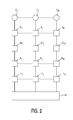
- FIG. 2 shows the receiving and demodulating means for the array of receiver coils are shown.
- Receiver coils C l ,...,C j ...,C n arranged in an array of receiver coils 16 are connected to receivers circuits R 1 ,...,R j ...,R n analog to digital converters AD l ,...,AD j ...,AD n , memories M l ,...,M j ...,M n , and Fourier transform means FT l ,...,FT j ...,FT n .
- N receiver coil images from MR signals preferably simultaneously, detected by the N receiver coils are determined in a well known way.
- the N receiver coil images are processed in processing means 14 to obtain the final image.
- MR signals are measured along a trajectory in k-space containing a first number NF of parallel lines in k-space by application of appropriate read gradients and other gradients.
- this number NF amounts to for example 256.
- the reduction factor RN can be chosen as a real number or integer number smaller than or equal to the number of receiver coils N.
- the number of phase encoding steps NF of the final image amounts to, for example, 128 and the number of receiver coils N amounts to, for example, five.
- the Fourier transform means reconstructs the single receiver coil images from the sets of MR signals, respectively.
- Each single receiver coil image is related to a field of view of the object which is reduced compared to the final field of view of the object related to the final image proportionally by the reduction factor.
- the field of view and the final field of view are related to the direction of the applied phase encoding gradients.
- the aliasing artefacts in pixels of a single receiver coil image are caused by a superposition of contributions of N equidistant voxels in the final field of view, a distance between the subsequent equidistant voxels being determined by the field of view.
- the field of view is defined by the trajectory in the k-space for which the N sets of MR signals of the related receiver coil image are measured.
- the generalised inverse of a matrix S is defined as a matrix product (S H S) -1 S H , wherein S H represents a complex conjugate transpose of the matrix S.
- the aliasing artefacts can be reduced further in the reconstructed final image by selecting the reduction factor such that the aliasing artefacts are laying outside the area of interest.
- the reduction factor for example, in cardiac imaging region of lung tissue can often be excluded from the image reconstruction due a negligible signal contribution.
- an optimal choice for the reduction factor will in that case be selected such that a high intensity fold-over of the back chest wall is directed of the heart into lung regions.
- the optimal choice for the reduction factor may be a non -integer number, smaller than the number of the receiver coils N in the receiver coil array 16.
- the reduction factor amounts to a non-integer number different type of aliasing artefacts will occur in the final image, for example, when the reduction factor RN has a value 2.5, a two-fold overlap as well as three-fold overlap will occur in the final image.
- an aliasing degree can be determined and taken into account by determining a dimension of the image vector b.
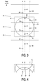
- Figure 3 shows a final field of view of an object.
- Figure 3 comprises a circle 30 representing an object to be imaged, for example the heart of a patient or a human being. Furthermore, figure 3 shows three adjacent field of views, a central field of view 32, a top field of view 31 and bottom field of view 33. These adjacent fields of view fit in a final field of view 34.
- the reduction factor RN is chosen such that an integer number of voxels fits in the field of view 31,32,33 of the single receiver coil images.
- the number RN equals 2.5. Contributions from voxels of adjacent fields of view 31,33 and a voxel of a central field of view 32 are then added to yield a pixel value of the single receiver coil image. In Figure 3 only the three adjacent field of view comprise material of the object 30.
- Figure 4 shows the single receiver coil image 60, comprising a superposition of the adjacent field of views 31,32,33.
- the contributing voxels of the final field 34 of view of figure 3 have to be separated.
- This superposition of adjacent fields of view is explained by way of example.
- Fig.3 shows three central voxels 35,45,55 in the central field of view 32 in fig. 3 and contributing voxels 36-39, 46-49,56-59 in the adjacent field of views 31,33.
- Fig. 4 shows the first, second and third pixels 61,62,63 in a single receiver coil image 60, which pixel values contains an infinite series of potentially contributing voxels.
- the dimension of the image vector b is determined by the number of the adjacent voxels in the subsequent fields of view 31,32,33, which are located in the final field of view 34, and a distance between subsequent equidistant voxels being equal to the field of view.
- the method comprises a further step of excluding volume-elements in the final field of view outside a predetermined region not comprising the object, from the reconstruction of the final image.
- the factor LG is calculated from the matrix S only, thus enabling a priori estimates of SRN and optimal choice of RN.
- those voxels which lie outside of the object as determined by a reference image are excluded from reconstruction and are set to zero in the final image.
- the three voxels 55,56,57 in the final field of view 34 contribute to the pixel 63 in the single receiver coil image 60.
- voxel 57 does not represent any structure of the object to contribute to the MR signal. So, in this example the dimension of the image vector b containing the pixels of the final image is determined by only two contributing voxels 55,56. The value of the excluded voxel 57 is set to zero in the final image.
- Different sensitivity matrices S can be determined respectively from sensitivity maps of the N receiver coils.
- a set of low resolution reference receiver coil images of arbitrary contrast are divided pixel wise by a reference image.
- a set of low resolution reference receiver coil images are reconstructed, from a set of, preferably, simultaneously acquired MR signals by separate MR imaging sequences.
- the set of simultaneously acquired MR signal can be measured, for example, by a known echo planar imaging (EPI) sequence.
- EPI echo planar imaging
- the EPI imaging sequence comprises an excitation of a RF pulse and, preferably, simultaneously measurement of five receiver coil reference sets of MR signals along a first number of parallel lines in k-space by application of a read gradient and other gradients on the static magnetic field.
- the first number of parallel lines corresponding with a reduced number of phase encoding steps compared to the number NF, for example 64 phase encoding steps.
- the first numbers of parallel lines are located around a central part of k-space such that a low resolution reference receiver coil images are obtained
- the reference image can be obtained, for example, by determining a square root of sum of squares of the reconstructed reference receiver coil images.
- Another possibility to obtain the reference is image is to reconstruct a body coil image from reference MR signals measured for example by a separate imaging sequence using the bodycoil 6.
- the pulse sequences used to measure the reference MR signals are of the same type as the pulse sequences used to measure the receiver coil images.
- the separate acquisition of MR signal for reconstruction of the reference image comprises generation of an RF excitation pulse and measurement of the reference MR signals along a second number of parallel lines in k-space by application of read gradient and other gradients, such as a phase encoding gradient.
- the second number is smaller than the number of phase encoding steps NF corresponding to the final image, for example, the second number equals 64.
- the second numbers of parallel lines are located around a central part of k-space such that a low resolution body coil image is obtained.
- the image volume of the reference image may be larger that the region of interest of the final field of view.
- the method comprises a step of filtering the raw sensitivity maps in order to obtain sensitivity maps covering a region larger than the heart to be imaged.
- said step of filtering comprises a low pass filter.
- sensitivity maps may be impaired with noise, in particular in regions with low or zero contribution to the MR signals said filter reduces also the noise.
- a two-dimensional polynomial fit technique is applied instead of said low pass filtering.
- a 2D polynomial is locally fit to the sensitivity map.
- a refined sensitivity value of the pixel is obtained by evaluation of the fitting polynomial at the position of the respective pixel in the sensitivity map. Fitting is based on valuable data of the sensitivity maps.
- Valuable data can be obtained by thresholding the sensitivity map according to signal strength in the body coil image and subsequent exclusion of isolated pixels, for example, by minimum neighbourhood filtering.
- the remaining pixels plus a predetermined neighbourhood determined by region growing of a region containing the remaining pixels, form the set for which refined sensitivity values are calculated by fitting.
- a width of the Gaussian kernel corresponds to a desired degree of smoothing.
- the field of view of the final image can be chosen so as to be rectangular.
- a 200 x 256 image may be sufficient to measure MR signals with EPI imaging sequence comprising 100 phase encoding steps when two receiver coils are employed.
- EPI imaging sequence comprising 100 phase encoding steps when two receiver coils are employed.
- a square image of 256x256 more phase encoding steps are necessary with the same number of receiver coils.
- the described method may also be applied in for example, functional imaging of the brain of a human or animal body.
Landscapes
- Physics & Mathematics (AREA)
- Condensed Matter Physics & Semiconductors (AREA)
- General Physics & Mathematics (AREA)
- Health & Medical Sciences (AREA)
- General Health & Medical Sciences (AREA)
- Nuclear Medicine, Radiotherapy & Molecular Imaging (AREA)
- Radiology & Medical Imaging (AREA)
- Engineering & Computer Science (AREA)
- Signal Processing (AREA)
- High Energy & Nuclear Physics (AREA)
- Magnetic Resonance Imaging Apparatus (AREA)
Priority Applications (1)
| Application Number | Priority Date | Filing Date | Title |
|---|---|---|---|
| EP10153702A EP2194392A1 (de) | 1998-04-17 | 1999-04-14 | SENSE: Empfindlichkeitskodierung für schnelle Magnetresonanzbildgebung |
Applications Claiming Priority (3)
| Application Number | Priority Date | Filing Date | Title |
|---|---|---|---|
| EP98201229 | 1998-04-17 | ||
| EP10153702A EP2194392A1 (de) | 1998-04-17 | 1999-04-14 | SENSE: Empfindlichkeitskodierung für schnelle Magnetresonanzbildgebung |
| EP99911966A EP0990169A1 (de) | 1998-04-17 | 1999-04-14 | Verfahren und gerät zur bilderzeugung durch magnetische resonanz |
Related Parent Applications (1)
| Application Number | Title | Priority Date | Filing Date |
|---|---|---|---|
| EP99911966.2 Division | 1999-04-14 |
Publications (1)
| Publication Number | Publication Date |
|---|---|
| EP2194392A1 true EP2194392A1 (de) | 2010-06-09 |
Family
ID=8233608
Family Applications (2)
| Application Number | Title | Priority Date | Filing Date |
|---|---|---|---|
| EP10153702A Withdrawn EP2194392A1 (de) | 1998-04-17 | 1999-04-14 | SENSE: Empfindlichkeitskodierung für schnelle Magnetresonanzbildgebung |
| EP99911966A Ceased EP0990169A1 (de) | 1998-04-17 | 1999-04-14 | Verfahren und gerät zur bilderzeugung durch magnetische resonanz |
Family Applications After (1)
| Application Number | Title | Priority Date | Filing Date |
|---|---|---|---|
| EP99911966A Ceased EP0990169A1 (de) | 1998-04-17 | 1999-04-14 | Verfahren und gerät zur bilderzeugung durch magnetische resonanz |
Country Status (8)
| Country | Link |
|---|---|
| US (1) | US6326786B1 (de) |
| EP (2) | EP2194392A1 (de) |
| JP (2) | JP4446495B2 (de) |
| KR (1) | KR100553464B1 (de) |
| CN (1) | CN1111746C (de) |
| BR (2) | BR9910347B8 (de) |
| RU (1) | RU2216751C2 (de) |
| WO (1) | WO1999054746A1 (de) |
Cited By (6)
| Publication number | Priority date | Publication date | Assignee | Title |
|---|---|---|---|---|
| CN102959426A (zh) * | 2010-07-02 | 2013-03-06 | 皇家飞利浦电子股份有限公司 | 使用欠采样线圈数据来估计线圈灵敏度的并行磁共振成像 |
| CN104749538A (zh) * | 2015-04-30 | 2015-07-01 | 郑州轻工业学院 | 一种并行磁共振成像相位处理方法 |
| US11185249B2 (en) | 2019-03-14 | 2021-11-30 | Hyperfine, Inc. | Self ensembling techniques for generating magnetic resonance images from spatial frequency data |
| US11300645B2 (en) | 2018-07-30 | 2022-04-12 | Hyperfine Operations, Inc. | Deep learning techniques for magnetic resonance image reconstruction |
| US11789104B2 (en) | 2018-08-15 | 2023-10-17 | Hyperfine Operations, Inc. | Deep learning techniques for suppressing artefacts in magnetic resonance images |
| EP4530656A1 (de) * | 2023-09-26 | 2025-04-02 | Koninklijke Philips N.V. | Bestimmung von ausleserichtungen und phasencodierungsrichtungen für parallele magnetresonanzbildgebung |
Families Citing this family (108)
| Publication number | Priority date | Publication date | Assignee | Title |
|---|---|---|---|---|
| US6289232B1 (en) | 1998-03-30 | 2001-09-11 | Beth Israel Deaconess Medical Center, Inc. | Coil array autocalibration MR imaging |
| WO2000072034A1 (en) | 1999-05-20 | 2000-11-30 | Koninklijke Philips Electronics N.V. | Magnetic resonance imaging method with sub-sampling |
| JP2003500135A (ja) * | 1999-05-20 | 2003-01-07 | コーニンクレッカ フィリップス エレクトロニクス エヌ ヴィ | サブサンプリングを具備する磁気共鳴撮像方法 |
| US6680610B1 (en) * | 1999-05-24 | 2004-01-20 | Walid E. Kyriakos | Apparatus and method for parallel MR data acquisition and parallel image reconstruction from multiple receiver coil arrays for fast MRI |
| GB9926918D0 (en) | 1999-11-15 | 2000-01-12 | Marconi Electronic Syst Ltd | Magnetic resonance imaging |
| GB9926923D0 (en) | 1999-11-15 | 2000-01-12 | Marconi Electronic Syst Ltd | Magnetic resonance imaging |
| WO2001044827A2 (en) * | 1999-12-15 | 2001-06-21 | Koninklijke Philips Electronics N.V. | Magnetic resonance method for forming a fast dynamic image |
| JP3847512B2 (ja) * | 2000-02-07 | 2006-11-22 | 株式会社日立メディコ | 磁気共鳴イメージング装置 |
| US6611143B2 (en) * | 2000-03-14 | 2003-08-26 | Kabushiki Kaisha Toshiba | MRI apparatus generating odd and/or even echo images with sensitivity distribution of coils |
| US6717406B2 (en) | 2000-03-14 | 2004-04-06 | Beth Israel Deaconess Medical Center, Inc. | Parallel magnetic resonance imaging techniques using radiofrequency coil arrays |
| JP4659993B2 (ja) * | 2000-03-14 | 2011-03-30 | 株式会社東芝 | 磁気共鳴映像装置 |
| JP4718714B2 (ja) * | 2000-04-25 | 2011-07-06 | 株式会社東芝 | 磁気共鳴イメージング装置及び磁気共鳴イメージング方法 |
| US6452388B1 (en) * | 2000-06-28 | 2002-09-17 | Baker Hughes Incorporated | Method and apparatus of using soft non-ferritic magnetic material in a nuclear magnetic resonance probe |
| EP1307758A1 (de) * | 2000-07-31 | 2003-05-07 | Koninklijke Philips Electronics N.V. | Verfahren der magnetischen resonanz zur erstellung eines schnellen dynamischen bildes |
| JP5085832B2 (ja) * | 2000-07-31 | 2012-11-28 | コーニンクレッカ フィリップス エレクトロニクス エヌ ヴィ | サブサンプリングされた捕捉を用いた磁気共鳴撮像方法 |
| EP1307759A1 (de) | 2000-07-31 | 2003-05-07 | Koninklijke Philips Electronics N.V. | Verfahren der magnetischen resonanz zur erstellung eines schnellen dynamischen bildes |
| DE10059772A1 (de) * | 2000-11-30 | 2002-06-13 | Philips Corp Intellectual Pty | MR-Bildrekonstruktion |
| DE10106830C2 (de) | 2001-02-14 | 2003-01-16 | Siemens Ag | Verfahren zur Bilderzeugung mittels magnetischer Resonanz mit mehreren unabhängigen Empfangsantennen |
| EP1371327A4 (de) * | 2001-02-23 | 2006-06-21 | Hitachi Medical Corp | Kernspintomographisches gerät und verfahren |
| EP1373919A1 (de) | 2001-03-23 | 2004-01-02 | Koninklijke Philips Electronics N.V. | Verfahren zur bildgebung mit magnetischer resonanz für eine abgewinkelte schnittebene |
| JP2002290868A (ja) * | 2001-03-27 | 2002-10-04 | Texas Instr Japan Ltd | 周波数変換回路、復調回路及びテレビ受信装置 |
| US6771067B2 (en) | 2001-04-03 | 2004-08-03 | The United States Of America As Represented By The Department Of Health And Human Services | Ghost artifact cancellation using phased array processing |
| US6724923B2 (en) * | 2001-04-13 | 2004-04-20 | Ge Medical Systems Global Technology Co., Llc | Automatic coil selection of multi-receiver MR data using fast prescan data analysis |
| GB2374673A (en) * | 2001-04-20 | 2002-10-23 | Marconi Medical Systems Uk Ltd | Magnetic Resonance Imaging |
| GB2374672A (en) * | 2001-04-20 | 2002-10-23 | Marconi Medical Systems Uk Ltd | Magnetic Resonance Imaging |
| GB2380549A (en) * | 2001-04-20 | 2003-04-09 | Marconi Medical Systems Uk Ltd | Magnetic Resonance Imaging |
| GB0121744D0 (en) * | 2001-04-20 | 2001-10-31 | Marconi Medical Systems Uk Ltd | Magnetic resonance imaging |
| US6559642B2 (en) * | 2001-05-09 | 2003-05-06 | Ge Medical Systems Global Technology Company, Llc | Calibration method for use with sensitivity encoding MRI acquisition |
| US6486671B1 (en) * | 2001-05-14 | 2002-11-26 | Ge Medical Systems Global Technologies Company Llc | MRI image quality improvement using matrix regularization |
| DE10126338A1 (de) * | 2001-05-30 | 2002-12-12 | Siemens Ag | Hochfrequenz-Spulenanordnung für ein Kernspintomographie-Gerät und Kernspintomorgraphie-Gerät |
| DE10128534C2 (de) * | 2001-06-13 | 2003-04-30 | Siemens Ag | Verfahren zur Bilderzeugung mittels magnetischer Resonanz mit mehreren Empfangsantennen |
| JP4285624B2 (ja) * | 2001-06-21 | 2009-06-24 | 富士フイルム株式会社 | 画像信号生成方法および装置 |
| JP4443079B2 (ja) * | 2001-09-13 | 2010-03-31 | 株式会社日立メディコ | 磁気共鳴イメージング装置及び磁気共鳴イメージング装置用rf受信コイル |
| US7197353B2 (en) * | 2001-09-14 | 2007-03-27 | General Electric Company | Sensitivity encoding MRI acquisition method |
| EP1454157A1 (de) | 2001-11-26 | 2004-09-08 | Koninklijke Philips Electronics N.V. | Magnetische resonanzbildgebung mit unterabtastung |
| JP4360912B2 (ja) * | 2001-11-26 | 2009-11-11 | コーニンクレッカ フィリップス エレクトロニクス エヌ ヴィ | 音響ノイズが低減された磁気共鳴撮像方法 |
| JP3455530B1 (ja) | 2001-12-14 | 2003-10-14 | 株式会社東芝 | Mr信号受信装置及び磁気共鳴イメージング装置 |
| DE60226648D1 (de) * | 2001-12-17 | 2008-06-26 | Koninkl Philips Electronics Nv | Verfahren der kernspintomographie |
| DE10163815A1 (de) | 2001-12-22 | 2003-07-03 | Philips Intellectual Property | Paralleles MR-Bildgebungsverfahren |
| DE10203237B4 (de) * | 2002-01-28 | 2006-08-17 | Siemens Ag | Verfahren zur Magnetresonanz-Bildgebung mit automatischer Anpassung des Messfeldes |
| EP1499908A1 (de) * | 2002-04-08 | 2005-01-26 | Koninklijke Philips Electronics N.V. | Datenverarbeitung zur bildung eines zusammengesetzten objekt-datensatzes aus basis-datensätzen |
| EP1506422A1 (de) * | 2002-05-13 | 2005-02-16 | Koninklijke Philips Electronics N.V. | Verfahren der kernspintomographie |
| JP2005525185A (ja) * | 2002-05-13 | 2005-08-25 | コーニンクレッカ フィリップス エレクトロニクス エヌ ヴィ | 磁場強度の関数としてのパラレルイメージングにおけるリダクションファクタの固有の限界 |
| AU2003224377A1 (en) | 2002-05-13 | 2003-11-11 | Koninklijke Philips Electronics N.V. | Prior-information-enhanced dynamic magnetic resonance imaging |
| JP2005525182A (ja) | 2002-05-13 | 2005-08-25 | コーニンクレッカ フィリップス エレクトロニクス エヌ ヴィ | サブエンコードされたシングルショット磁気共鳴イメージングにおける磁化率アーチファクトの減少法 |
| AU2003224388A1 (en) * | 2002-05-13 | 2003-11-11 | Koninklijke Philips Electronics N.V. | Magnetic resonance imaging method with accelerated data acquisition |
| JP4030805B2 (ja) | 2002-06-07 | 2008-01-09 | ジーイー・メディカル・システムズ・グローバル・テクノロジー・カンパニー・エルエルシー | コイル感度マップ作成方法およびmri装置 |
| DE10226488A1 (de) | 2002-06-14 | 2003-12-24 | Philips Intellectual Property | MR-Anordnung mit unterschiedlich optimierten Hochfrequenzspulenarrays |
| US6833700B2 (en) * | 2002-09-13 | 2004-12-21 | General Electric Company | Method and apparatus for reconstruction of images in parallel MRI systems |
| US6980002B1 (en) | 2002-11-04 | 2005-12-27 | General Electric Company | Integrated cervical-thoracic-lumbar spine MRI array coil |
| WO2004048991A1 (en) * | 2002-11-26 | 2004-06-10 | Koninklijke Philips Electronics N.V. | Determination of subencoding mri coil sensitivities in a lower order magnetic field |
| JP2006524083A (ja) | 2003-04-23 | 2006-10-26 | コーニンクレッカ フィリップス エレクトロニクス エヌ ヴィ | Mr画像の再構築方法 |
| DE10318682B4 (de) * | 2003-04-24 | 2011-12-29 | Peter M. Jakob | Beschleunigte Magnet-Resonanz-Bildgebung im Rahmen der parallelen Akquisition von MRT-Daten |
| JP4607431B2 (ja) | 2003-05-08 | 2011-01-05 | 株式会社東芝 | Mri装置 |
| DE10339019B4 (de) * | 2003-08-25 | 2007-02-08 | Siemens Ag | Verfahren zur Bestimmung eines Beschleunigungsfaktors einer parallelen Bildaufnahme |
| US6919722B2 (en) * | 2003-10-09 | 2005-07-19 | Ge Medical Systems Global Technology Company, Llc | Image quality improvement for SENSE with low signal regions |
| DE10353342B4 (de) * | 2003-11-14 | 2008-07-17 | Siemens Ag | Verbesserte MRT-Bildgebung auf Basis konventioneller PPA-Rekonstruktionsverfahren |
| CN100543490C (zh) * | 2003-11-19 | 2009-09-23 | 通用电气公司 | 用于mri的缩放相控阵列膝线圈 |
| JP4130405B2 (ja) * | 2003-12-22 | 2008-08-06 | ジーイー・メディカル・システムズ・グローバル・テクノロジー・カンパニー・エルエルシー | 磁気共鳴撮影装置 |
| JP4037385B2 (ja) * | 2004-04-23 | 2008-01-23 | ジーイー・メディカル・システムズ・グローバル・テクノロジー・カンパニー・エルエルシー | 画像生成方法およびmri装置 |
| DE102004052894B4 (de) * | 2004-11-02 | 2007-03-01 | Siemens Ag | Optimiertes Verfahren zur Vermeidung von Einfaltungsartefakten in der Magnetresonanztomographie sowie Magnetresonanztomographiegerät und Computersoftwareprodukt |
| US7394253B2 (en) * | 2004-11-16 | 2008-07-01 | Kabushiki Kaisha Toshiba | Radio frequency coil assembly and magnetic resonance imaging apparatus |
| CN100396240C (zh) * | 2005-02-28 | 2008-06-25 | 西门子(中国)有限公司 | 频域灵敏度编码磁共振并行成像方法 |
| DE102005018937B4 (de) * | 2005-04-22 | 2007-11-22 | Siemens Ag | Verfahren und Gerät zur verbesserten sendeseitig beschleunigten PPA-basierten Volumen-selektiven Magnet-Resonanz-Bildgebung sowie Computersoftwareprodukt zur Implementierung des Verfahrens |
| US7446529B2 (en) | 2005-07-21 | 2008-11-04 | Kabushiki Kaisha Toshiba | Magnetic resonance imaging apparatus and radio frequency coil unit |
| US7397242B2 (en) * | 2005-10-27 | 2008-07-08 | Wisconsin Alumni Research Foundation | Parallel magnetic resonance imaging method using a radial acquisition trajectory |
| US7583082B1 (en) | 2006-04-19 | 2009-09-01 | University Of Virginia Patent Foundation | Partially parallel magnetic resonance imaging using arbitrary k-space trajectories with image reconstruction based on successive convolution operations |
| DE102006024976B3 (de) * | 2006-05-29 | 2007-10-31 | Siemens Ag | Verfahren und Gerät zur verbesserten sensitivitätskodierten Magnet-Resonanz-Bildgebung unter Verwendung eines Empfängerspulenarrays |
| DE102006025915A1 (de) * | 2006-06-02 | 2007-12-06 | Siemens Ag | Verfahren zur Darstellung des Herzens und Magnetresonanzanlage hierfür |
| US7888935B1 (en) | 2007-02-23 | 2011-02-15 | University Of Virginia Patent Foundation | K-space trajectory estimation in spiral MRI system and related method thereof |
| US8306289B1 (en) | 2007-02-23 | 2012-11-06 | University Of Virginia Patent Foundation | Method and system for off-resonance correction for non-cartesian parallel image reconstruction |
| JP2008229277A (ja) * | 2007-03-23 | 2008-10-02 | Ge Medical Systems Global Technology Co Llc | 磁気共鳴イメージング装置、磁気共鳴イメージング方法、および、感度分布計測装置 |
| US7394252B1 (en) | 2007-05-03 | 2008-07-01 | The General Hospital Corporation | Regularized GRAPPA reconstruction |
| JP5336731B2 (ja) * | 2007-12-17 | 2013-11-06 | 株式会社日立メディコ | 磁気共鳴イメージング装置 |
| DE102008004256B4 (de) * | 2008-01-14 | 2010-01-07 | Siemens Aktiengesellschaft | SAR-optimierte Ansteuerung eines Spulenarrays |
| US7902825B2 (en) * | 2008-05-19 | 2011-03-08 | The Board Of Trustees Of The Leland Stanford Junior University | Motion corrected tensor magnetic resonance imaging |
| JP5955891B2 (ja) * | 2008-07-01 | 2016-07-20 | 東芝メディカルシステムズ株式会社 | 磁気共鳴イメージング装置および受信経路切り替え方法 |
| DE102009015783A1 (de) * | 2009-03-31 | 2010-10-14 | Siemens Aktiengesellschaft | Neurologisches Sequenzprotokoll |
| EP2517036A1 (de) * | 2009-12-21 | 2012-10-31 | Koninklijke Philips Electronics N.V. | Magnetiresonanz-elastografie |
| DE102010011968A1 (de) * | 2010-03-03 | 2011-09-08 | Universität Duisburg-Essen | Verfahren zur Erzeugung eines Bilds mit einem Magnetresonanztomographen |
| DE102010003552B4 (de) * | 2010-03-31 | 2012-03-22 | Universitätsklinikum Freiburg | Verfahren zur Homogenisierung der Auflösung in Magnetresonanz-Tomographie-Aufnahmen unter Verwendung von nicht-linearen Kodierfeldern |
| RU2582474C2 (ru) * | 2010-08-20 | 2016-04-27 | Конинклейке Филипс Электроникс Н.В. | Эмуляция виртуальных катушек в мрт с параллельной передачей |
| DE102010043370B4 (de) * | 2010-11-04 | 2014-03-13 | Siemens Aktiengesellschaft | Kombination von MR-Signalen mit Unterdrückung unerwünschter Signalanteile |
| CN103282790B (zh) * | 2010-12-21 | 2016-01-27 | 皇家飞利浦电子股份有限公司 | 快速双对比度mr成像 |
| US9089274B2 (en) | 2011-01-31 | 2015-07-28 | Seiko Epson Corporation | Denoise MCG measurements |
| US9146330B2 (en) * | 2011-03-29 | 2015-09-29 | Westerngeco L.L.C. | Selecting a survey setting for characterizing a target structure |
| DE102011007501B3 (de) * | 2011-04-15 | 2012-05-31 | Universitätsklinikum Freiburg | Verfahren der bildgebenden Magnetresonanz zur Selektion und Aufnahme von gekrümmten Schichten |
| BR112014015398A8 (pt) * | 2011-12-23 | 2017-07-04 | Koninklijke Philips Nv | método de obtenção de imagem por mr de um corpo colocado no volume de exame de um dispositivo mr, dispositivo de mr para realizar o método e programa de computador a ser executado em um dispositivo de mr |
| WO2013110062A1 (en) * | 2012-01-20 | 2013-07-25 | The General Hospital Corporation | System and method for field map estimation |
| EP2626718A1 (de) * | 2012-02-09 | 2013-08-14 | Koninklijke Philips Electronics N.V. | Magnetresonanzbildgebung mit Bewegungskorrektur unter Verwendung von Navigatoren, welche mit einem Dixon-Verfahren erhalten wurden |
| US9146293B2 (en) | 2012-02-27 | 2015-09-29 | Ohio State Innovation Foundation | Methods and apparatus for accurate characterization of signal coil receiver sensitivity in magnetic resonance imaging (MRI) |
| US9846217B2 (en) | 2012-03-26 | 2017-12-19 | Koninklijke Philips N.V. | Through-plane navigator |
| US10151815B2 (en) | 2012-05-23 | 2018-12-11 | Konninklijke Philips N.V. | Multi-echo PRESTO |
| WO2014037868A1 (en) | 2012-09-06 | 2014-03-13 | Koninklijke Philips N.V. | Magnetic resonance imaging system with navigator-based motion detection |
| US10541451B2 (en) | 2012-10-18 | 2020-01-21 | Ambri Inc. | Electrochemical energy storage devices |
| EP2972450B1 (de) * | 2013-03-13 | 2021-02-17 | Koninklijke Philips N.V. | Automatische optimierung von beschleunigungsparametern in der parallelbildgebung |
| US10270139B1 (en) | 2013-03-14 | 2019-04-23 | Ambri Inc. | Systems and methods for recycling electrochemical energy storage devices |
| EP2972449B1 (de) | 2013-03-15 | 2021-07-28 | Koninklijke Philips N.V. | Parallele mehrschichtige magnetresonanzbildgebung mittels phasenmodulierter hf-impulse |
| EP3183594A1 (de) * | 2014-08-22 | 2017-06-28 | Koninklijke Philips N.V. | Parallele mr-bildgebung mit nyquist-ghost-korrektur für epi |
| JP6568210B2 (ja) * | 2014-09-26 | 2019-08-28 | コーニンクレッカ フィリップス エヌ ヴェKoninklijke Philips N.V. | シングルボクセル分光法のための撮像システム |
| CN107479014B (zh) * | 2016-06-03 | 2020-09-29 | 西门子(深圳)磁共振有限公司 | 磁共振线圈的选择方法和装置 |
| US11276174B2 (en) | 2019-02-21 | 2022-03-15 | Medtronic Navigation, Inc. | Method and apparatus for magnetic resonance imaging thermometry |
| US11426229B2 (en) | 2019-02-21 | 2022-08-30 | Medtronic Navigation, Inc. | Method and apparatus for magnetic resonance imaging thermometry |
| US11403760B2 (en) * | 2019-02-21 | 2022-08-02 | Medtronic Navigation, Inc. | Method and apparatus for magnetic resonance imaging thermometry |
| EP3709040B1 (de) * | 2019-03-13 | 2025-04-30 | Siemens Healthineers AG | Verfahren zum betrieb einer magnetfeldkamera |
| CN111127586B (zh) * | 2019-12-14 | 2021-10-29 | 深圳先进技术研究院 | 一种动脉输入函数曲线生成方法及装置 |
| CN115728688A (zh) * | 2021-08-31 | 2023-03-03 | 通用电气精准医疗有限责任公司 | 磁共振系统以及匀场方法,成像方法 |
| US12078696B2 (en) * | 2022-10-06 | 2024-09-03 | GE Precision Healthcare LLC | Silent calibration for magnetic resonance imaging |
Citations (2)
| Publication number | Priority date | Publication date | Assignee | Title |
|---|---|---|---|---|
| EP0412824A2 (de) * | 1989-08-09 | 1991-02-13 | Kabushiki Kaisha Toshiba | Anordnung zur Bilderzeugung mittels magnetischer Resonanz |
| EP0803738A1 (de) * | 1996-04-24 | 1997-10-29 | Philips Patentverwaltung GmbH | Bild-Synthese-Verfahren zur Erzeugung eines Kombinationsbildes aus Ausgangsbildern |
Family Cites Families (7)
| Publication number | Priority date | Publication date | Assignee | Title |
|---|---|---|---|---|
| RU2063702C1 (ru) * | 1992-07-20 | 1996-07-20 | Леонид Аврамович Тютин | Способ магнитно-резонансной томографии и устройство для его осуществления |
| RU2047871C1 (ru) * | 1992-12-23 | 1995-11-10 | Российский научный центр "Курчатовский институт" | Устройство магниторезонансного томографа |
| JPH0731606A (ja) * | 1993-07-22 | 1995-02-03 | Shimadzu Corp | 磁気共鳴断層撮影装置 |
| US5399970A (en) * | 1993-08-11 | 1995-03-21 | Board Of Trustees Of The Leland Stanford Junior University | Phase-contrast MRI using phased-array multicoil |
| DE4427497C2 (de) * | 1994-08-03 | 1996-06-20 | Siemens Ag | Pulssequenz für ein Kernspintomographiegerät |
| RU2074401C1 (ru) * | 1994-11-09 | 1997-02-27 | Акционерное общество Научно-производственная фирма "АЗ" | Способ компенсации внешних магнитных полей помех при создании магнито-резонансного изображения и устройство для его осуществления |
| US5808467A (en) * | 1995-05-31 | 1998-09-15 | Hitachi, Ltd. | RF probe and inspection system using NMR using the same |
-
1999
- 1999-04-14 JP JP55268099A patent/JP4446495B2/ja not_active Expired - Lifetime
- 1999-04-14 EP EP10153702A patent/EP2194392A1/de not_active Withdrawn
- 1999-04-14 BR BRPI9910347A patent/BR9910347B8/pt not_active IP Right Cessation
- 1999-04-14 EP EP99911966A patent/EP0990169A1/de not_active Ceased
- 1999-04-14 KR KR1019997011899A patent/KR100553464B1/ko not_active Expired - Fee Related
- 1999-04-14 WO PCT/IB1999/000652 patent/WO1999054746A1/en not_active Ceased
- 1999-04-14 RU RU2000100924/09A patent/RU2216751C2/ru active
- 1999-04-14 US US09/446,237 patent/US6326786B1/en not_active Expired - Lifetime
- 1999-04-14 CN CN99800499A patent/CN1111746C/zh not_active Expired - Lifetime
- 1999-04-14 BR BR9810032-7A patent/BR9810032A/pt unknown
-
2009
- 2009-07-02 JP JP2009157564A patent/JP4443625B2/ja not_active Expired - Lifetime
Patent Citations (2)
| Publication number | Priority date | Publication date | Assignee | Title |
|---|---|---|---|---|
| EP0412824A2 (de) * | 1989-08-09 | 1991-02-13 | Kabushiki Kaisha Toshiba | Anordnung zur Bilderzeugung mittels magnetischer Resonanz |
| EP0803738A1 (de) * | 1996-04-24 | 1997-10-29 | Philips Patentverwaltung GmbH | Bild-Synthese-Verfahren zur Erzeugung eines Kombinationsbildes aus Ausgangsbildern |
Non-Patent Citations (6)
| Title |
|---|
| D.K. SODICKSON ET AL., SIMULTANEOUS ACQUISITION OF SPATIAL HARMONIC (SMASH): FAST IMAGING WITH RADIO FREQUENCY COIL ARRAY, vol. 38, 1997, pages 591 - 603 |
| J.B.RA ET AL.: "Fast Imaging Method Using Multiple Receiver Coils with Subencoding Data Set", PROC. OF THE SMRM 1991, WORKS IN PROGRESS, 1991, pages 1240, XP002577628 * |
| J.R.KELTON ET AL.: "An Algorithm For Rapid Image Acquisition Using Multiple Receiver Coils", PROC. OF THE SMRM 1989, WORKS IN PROGRESS, 1989, pages 1172, XP002577627 * |
| KLINGER A: "Approximate pseudoinverse solutions to ill-conditioned linear systems", JOURNAL OF OPTIMIZATION THEORY AND APPLICATIONS, PLENUM PRESS, LONDON, GB LNKD- DOI:10.1007/BF00929587, vol. 2, no. 2, 1 March 1968 (1968-03-01), pages 117 - 124, XP009088522, ISSN: 0022-3239 * |
| M.T. VLAARDINGERBROEK: "Magnetic Resonance Imaging", 1996, SPINGER VERLAG |
| RA J B ET AL: "FAST IMAGING USING SUBENCODING DATA SETS FROM MULTIPLE DETECTORS", MAGNETIC RESONANCE IN MEDICINE, ACADEMIC PRESS, DULUTH, MN, US, vol. 30, no. 1, 1 July 1993 (1993-07-01), pages 142 - 145, XP000382650, ISSN: 0740-3194 * |
Cited By (15)
| Publication number | Priority date | Publication date | Assignee | Title |
|---|---|---|---|---|
| CN102959426A (zh) * | 2010-07-02 | 2013-03-06 | 皇家飞利浦电子股份有限公司 | 使用欠采样线圈数据来估计线圈灵敏度的并行磁共振成像 |
| CN104749538A (zh) * | 2015-04-30 | 2015-07-01 | 郑州轻工业学院 | 一种并行磁共振成像相位处理方法 |
| CN104749538B (zh) * | 2015-04-30 | 2016-02-03 | 郑州轻工业学院 | 一种并行磁共振成像相位处理方法 |
| US11467239B2 (en) | 2018-07-30 | 2022-10-11 | Hyperfine Operations, Inc. | Deep learning techniques for magnetic resonance image reconstruction |
| US12181553B2 (en) | 2018-07-30 | 2024-12-31 | Hyperfine Operations, Inc. | Deep learning techniques for magnetic resonance image reconstruction |
| US11300645B2 (en) | 2018-07-30 | 2022-04-12 | Hyperfine Operations, Inc. | Deep learning techniques for magnetic resonance image reconstruction |
| US11789104B2 (en) | 2018-08-15 | 2023-10-17 | Hyperfine Operations, Inc. | Deep learning techniques for suppressing artefacts in magnetic resonance images |
| US11344219B2 (en) | 2019-03-14 | 2022-05-31 | Hyperfine Operations, Inc. | Deep learning techniques for alignment of magnetic resonance images |
| US11564590B2 (en) | 2019-03-14 | 2023-01-31 | Hyperfine Operations, Inc. | Deep learning techniques for generating magnetic resonance images from spatial frequency data |
| US11681000B2 (en) | 2019-03-14 | 2023-06-20 | Hyperfine Operations, Inc. | Self ensembling techniques for generating magnetic resonance images from spatial frequency data |
| US11324418B2 (en) | 2019-03-14 | 2022-05-10 | Hyperfine Operations, Inc. | Multi-coil magnetic resonance imaging using deep learning |
| US12105173B2 (en) | 2019-03-14 | 2024-10-01 | Hyperfine Operations, Inc. | Self ensembling techniques for generating magnetic resonance images from spatial frequency data |
| US11185249B2 (en) | 2019-03-14 | 2021-11-30 | Hyperfine, Inc. | Self ensembling techniques for generating magnetic resonance images from spatial frequency data |
| EP4530656A1 (de) * | 2023-09-26 | 2025-04-02 | Koninklijke Philips N.V. | Bestimmung von ausleserichtungen und phasencodierungsrichtungen für parallele magnetresonanzbildgebung |
| WO2025068030A1 (en) * | 2023-09-26 | 2025-04-03 | Koninklijke Philips N.V. | Determining readout directions and phase encoding directions for parallel magnetic resonance imaging |
Also Published As
| Publication number | Publication date |
|---|---|
| JP2010012270A (ja) | 2010-01-21 |
| EP0990169A1 (de) | 2000-04-05 |
| JP4443625B2 (ja) | 2010-03-31 |
| BR9910347B1 (pt) | 2012-08-07 |
| KR100553464B1 (ko) | 2006-02-22 |
| JP4446495B2 (ja) | 2010-04-07 |
| CN1111746C (zh) | 2003-06-18 |
| BR9810032A (pt) | 2000-09-19 |
| BR9910347B8 (pt) | 2021-06-22 |
| JP2002505613A (ja) | 2002-02-19 |
| CN1263601A (zh) | 2000-08-16 |
| RU2216751C2 (ru) | 2003-11-20 |
| KR20010013877A (ko) | 2001-02-26 |
| WO1999054746A1 (en) | 1999-10-28 |
| US6326786B1 (en) | 2001-12-04 |
Similar Documents
| Publication | Publication Date | Title |
|---|---|---|
| US6326786B1 (en) | Magnetic resonance imaging method and apparatus | |
| US6289232B1 (en) | Coil array autocalibration MR imaging | |
| Sodickson et al. | Simultaneous acquisition of spatial harmonics (SMASH): fast imaging with radiofrequency coil arrays | |
| EP1015903B1 (de) | Gleichzeitige aufzeichnung räumlicher basisfunktionen: schnelle bilderfassung mit hilfe von radiofrequenz-spulenanordnungen | |
| US6559642B2 (en) | Calibration method for use with sensitivity encoding MRI acquisition | |
| US7224163B2 (en) | Magnetic resonance imaging device | |
| US7372269B2 (en) | Magnetic resonance imaging method and apparatus | |
| US5759152A (en) | Phase-aligned NMR surface coil image reconstruction | |
| EP2008118B1 (de) | Trennung von metaboliten mit abbildung der chemischen verschiebung | |
| US20070096732A1 (en) | Parallel magnetic resonance imaging method using a radial acquisition trajectory | |
| EP0633480A1 (de) | Unterdrückung von Artefakten in der Bilderzeugung durch GRASE magnetische Resonanz | |
| CN103140167B (zh) | 化学物类的磁共振成像 | |
| EP2646843A2 (de) | Mr-bildgebung mit einer mehrpunkt-dixon-technik | |
| US20040239324A1 (en) | Method and system for accelerated imaging using parallel MRI | |
| US7197353B2 (en) | Sensitivity encoding MRI acquisition method | |
| WO2011055268A1 (en) | Mr imaging using navigators | |
| EP1372110B1 (de) | Bildrekonstruktionsverfahren und -system | |
| US20060058629A1 (en) | Magnetic resonance method | |
| US10955506B2 (en) | Parallel MR imaging with spectral fat suppression | |
| US6915152B2 (en) | Method for MR imaging with an array of RF coils | |
| JP2002248089A (ja) | 磁気共鳴イメージング装置および方法 | |
| US20210270918A1 (en) | Method for generating a magnetic resonance image |
Legal Events
| Date | Code | Title | Description |
|---|---|---|---|
| PUAI | Public reference made under article 153(3) epc to a published international application that has entered the european phase |
Free format text: ORIGINAL CODE: 0009012 |
|
| AC | Divisional application: reference to earlier application |
Ref document number: 0990169 Country of ref document: EP Kind code of ref document: P |
|
| AK | Designated contracting states |
Kind code of ref document: A1 Designated state(s): DE FR GB NL SE |
|
| 17P | Request for examination filed |
Effective date: 20101209 |
|
| STAA | Information on the status of an ep patent application or granted ep patent |
Free format text: STATUS: THE APPLICATION IS DEEMED TO BE WITHDRAWN |
|
| 18D | Application deemed to be withdrawn |
Effective date: 20101210 |