EP2194724A1 - Dispositif d'enregistrement de diffusion numérique - Google Patents
Dispositif d'enregistrement de diffusion numérique Download PDFInfo
- Publication number
- EP2194724A1 EP2194724A1 EP20090177904 EP09177904A EP2194724A1 EP 2194724 A1 EP2194724 A1 EP 2194724A1 EP 20090177904 EP20090177904 EP 20090177904 EP 09177904 A EP09177904 A EP 09177904A EP 2194724 A1 EP2194724 A1 EP 2194724A1
- Authority
- EP
- European Patent Office
- Prior art keywords
- recording
- mode
- audio signal
- recording medium
- compatible
- Prior art date
- Legal status (The legal status is an assumption and is not a legal conclusion. Google has not performed a legal analysis and makes no representation as to the accuracy of the status listed.)
- Ceased
Links
- 230000005236 sound signal Effects 0.000 claims abstract description 62
- 230000009977 dual effect Effects 0.000 claims abstract description 61
- 238000000034 method Methods 0.000 claims description 4
- 238000010586 diagram Methods 0.000 description 8
- 238000004891 communication Methods 0.000 description 5
- 230000006835 compression Effects 0.000 description 3
- 238000007906 compression Methods 0.000 description 3
- 230000006870 function Effects 0.000 description 3
- 230000001771 impaired effect Effects 0.000 description 3
- 230000004048 modification Effects 0.000 description 3
- 238000012986 modification Methods 0.000 description 3
- 101001121408 Homo sapiens L-amino-acid oxidase Proteins 0.000 description 2
- 102100026388 L-amino-acid oxidase Human genes 0.000 description 2
- 206010011416 Croup infectious Diseases 0.000 description 1
- 101000969688 Homo sapiens Macrophage-expressed gene 1 protein Proteins 0.000 description 1
- 102100021285 Macrophage-expressed gene 1 protein Human genes 0.000 description 1
- 201000010549 croup Diseases 0.000 description 1
- 238000005516 engineering process Methods 0.000 description 1
- 230000003287 optical effect Effects 0.000 description 1
Images


Classifications
-
- H—ELECTRICITY
- H04—ELECTRIC COMMUNICATION TECHNIQUE
- H04N—PICTORIAL COMMUNICATION, e.g. TELEVISION
- H04N9/00—Details of colour television systems
- H04N9/79—Processing of colour television signals in connection with recording
- H04N9/80—Transformation of the television signal for recording, e.g. modulation, frequency changing; Inverse transformation for playback
- H04N9/804—Transformation of the television signal for recording, e.g. modulation, frequency changing; Inverse transformation for playback involving pulse code modulation of the colour picture signal components
- H04N9/806—Transformation of the television signal for recording, e.g. modulation, frequency changing; Inverse transformation for playback involving pulse code modulation of the colour picture signal components with processing of the sound signal
- H04N9/8063—Transformation of the television signal for recording, e.g. modulation, frequency changing; Inverse transformation for playback involving pulse code modulation of the colour picture signal components with processing of the sound signal using time division multiplex of the PCM audio and PCM video signals
-
- H—ELECTRICITY
- H04—ELECTRIC COMMUNICATION TECHNIQUE
- H04N—PICTORIAL COMMUNICATION, e.g. TELEVISION
- H04N5/00—Details of television systems
- H04N5/76—Television signal recording
- H04N5/78—Television signal recording using magnetic recording
- H04N5/781—Television signal recording using magnetic recording on disks or drums
-
- H—ELECTRICITY
- H04—ELECTRIC COMMUNICATION TECHNIQUE
- H04N—PICTORIAL COMMUNICATION, e.g. TELEVISION
- H04N5/00—Details of television systems
- H04N5/76—Television signal recording
- H04N5/84—Television signal recording using optical recording
- H04N5/85—Television signal recording using optical recording on discs or drums
Definitions
- the present invention generally relates to a digital broadcast recording device. More specifically, the present invention relates to a digital broadcast recording device with which a digital broadcast signal is received and recorded to a recording medium. Background Information
- MPEG2 With MPEG2 standards, there are two different formats.
- One format is MPEG2-PS (program stream), which deals with recording medium such as DVDs (digital versatile disks) and hard disks and with which a single program (such as a movie or a TV show) is multiplexed.
- MPEG2-TS transport stream
- MPEG2-TS transport stream
- a program received by a digital broadcast service is outputted to and recorded and reproduced by a recording device that handles data of different compression formats, such as MPEG2-PS and MPEG2-TS (see Japanese Laid-Open Patent Application No. 119-322148 , for example).
- the outputted data can be edited to the output format compatible with the recording device.
- an audio commentary e.g., audio description
- the main audio is multiplexed with an MPEG2 Audio Layer 2
- the audio description hereinafter referred to as "AD audio"
- the user mixes the AD audio with the main audio.
- MPEG2-TS recording there are two different recording systems: MPEG2-TS recording and MPEG2-PS recording.
- TS recording with a Blu-Ray disk compatible with the TS recording or a hard disk with no limitations in terms of standards, even though the main audio and the AD audio are recorded without modification at the recording stage, during reproduction the user can switch between outputting just the main audio, outputting just the AD audio, and mixing the AD audio with the main audio.
- the PS recording In the case of the PS recording, however, if the main audio and the AD audio are recorded at the recording stage, during reproduction the user cannot mix the AD audio with the main audio. This is because the PS recording is set this way by standard (specifically, there is no standard for mixing the main audio and the AD audio). Accordingly, in the case of the PS recording, the main audio and the AD audio have to be mixed and recorded at the recording stage. In this case, however, if the PS recording is performed in normal stereo mode, then during reproduction the user is unable to switch the audio so that only the main audio is heard or only the AD audio is heard.
- One object of the present invention is to provide a digital broadcast recording device with which a digital broadcast signal is adequately recorded by a PS recording so that a main audio signal and a sub audio signal can be adequately switched during reproduction.
- a digital broadcast recording receives a digital broadcast signal with a main audio signal and a sub audio signal, and records the digital broadcast signal to a recording medium.
- the digital broadcast recording device includes decision means and recording means.
- the decision means decides whether or not the recording medium is compatible with a dual mono mode during a PS (Program Stream) recording mode in which the digital broadcast signal is recorded by a PS recording.
- the recording means records the sub audio signal along with the main audio in a stereo mode when the decision means decides that the recording medium is not compatible with the dual mono mode, and records the sub audio signal and the main audio signal in the dual mono mode when the decision means decides that the recording medium is compatible with the dual mono mode.
- the digital broadcast recording device of the present invention it is possible to provide a digital broadcast recording device with which a digital broadcast signal is adequately recorded by a PS recording so that a main audio signal and a sub audio signal can be adequately switched during reproduction.
- FIG. 1 is a functional block diagram of a DVD recorder in accordance with one embodiment of the present invention
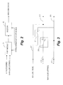
- FIG. 2 is a block diagram of a signal processing circuit of the DVD recorder illustrated in FIG. 1 ;
- FIG. 3 is a schematic circuit diagram of the signal processing circuit illustrated in FIG. 2 ;
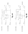
- FIG. 4a is a schematic circuit diagram of the signal processing circuit in an AD stereo mode
- FIG. 4b is a schematic circuit diagram of the signal processing circuit in an AD dual mono mode.
- FIG. 5 is a flowchart illustrating a recording processing operation when a main audio and an AD audio included in a digital broadcast signal are recorded by a PS recording.
- FIG. 1 is a functional block diagram of a DVD recorder (e.g., digital broadcast recording device) 1.
- the DVD recorder 1 mainly includes a tuner 2, a signal processing circuit 3, a storage controller 4, a DVD component 5, a built-in hard disk drive (HDD) component 6 with a hard disk, an on-screen character display (OSD) circuit 8, an audio output circuit 9, a microprocessor 12, a memory 13, and a remote control receiver 15.
- the tuner 2 is electrically coupled to an antenna 16, and receives a television broadcast of MPEG compressed digital broadcast signal through the antenna 16.
- the tuner 2 further receives a program of a channel from the television broadcast.
- the signal processing circuit 3 processes video and audio signals of the program received by the tuner 2.
- the DVD component 5 receives the processed video and audio signals via the storage controller 4, records the processed video and audio signals to a DVD or other such optical disk, and reproduces the video signal and the audio signal recorded on the DVD.
- the HDD component 6 receives the processed video and audio signals via the storage controller 4, records the processed video and audio signals to the hard disk, and reproduces data recorded on the hard disk.
- the storage controller 4 is operatively coupled to the signal processing circuit 3, the DVD component 5 and the HDD component 6, and controls the recording and reproduction of the DVD component 5 and the HDD component 6.
- the OSD circuit 8 is electrically coupled to a monitor device 40, and displays character information signal superposed with the video signal on the monitor device 40.
- the audio output circuit 9 is electrically coupled to a speaker 50, and amplifies the audio signal and drives the speaker 50.
- the microprocessor 12 controls the entire system of the DVD recorder 1.
- the memory 13 includes an EEPROM or flash memory.
- the memory 13 stores various kinds of data.
- the remote control receiver 15 receives an infrared remote control signal sent from a remote control 20 and converts it into a specific electrical signal.
- AD audio sub audio signal
- main audio e.g., main audio signal
- the monaural AD audio has to be mixed with the stereo main audio.
- the audio signal when the audio signal is subjected to the PS recording to a DVD, HDD, or other storage medium, the user can not switch the recorded audio signal between "with AD audio” (the main audio and the AD audio), "without AD audio” (the main audio only), and "only the AD audio.”
- the DVD recorder 1 the audio signal is subjected to dual mono mode recording only during the PS recording, and then dual mono reproduction of the PS recording is employed during reproduction.
- the user can switch between the main audio and the AD audio during reproduction.
- the dual mono mode is a mode in which two types of monophonic audio (e.g., the main audio and the AD audio) are simultaneously recorded (to the left and right channel) is permitted as a mode for audio recording.
- the dual mono mode recording can not be performed.
- stereo mode recording is performed.
- the main audio is recorded in stereo mode to the left and right channels, and the AD audio is also recorded in stereo mode at the same time by multiplexing to the left and right channels. Therefore, in this case switching between the main audio and the AD audio during reproduction can not be performed.
- the recording medium is compatible with the dual mono mode (such as when the recording medium is one of the HDD, DVD-R in VR (Video Recording) mode and DVD-RW in VR mode (e.g., DVD-VR))
- the AD audio is recorded, for example, to the left channel
- the stereo main audio is recorded monaurally to the right channel. Consequently, during reproduction the left and right channels are both reproduced so that the main audio and the AD audio can be mixed in the output audio.
- just the left channel is reproduced, then just the AD audio can be outputted.
- just the main audio can be outputted (in this case, however, the reproduction is monaural).
- FIG. 2 is a block diagram of an internal configuration of the signal processing circuit 3.
- FIG. 2 mainly shows an audio signal processing portion of the signal processing circuit 3.
- the processing of the video signal is the same as in the conventional device, so it is not depicted or described here.
- the signal processing circuit 3 has a DVB-T module 31 and an encoder 32.
- the DVB-T module 31 receives the video and audio signals that have undergone MPEG compression. Specifically, as shown in FIG. 2 , The DVB-T module 31 receives the monaural AD audio and the stereo main audio from the signal of the video and audio data of the program received by the tuner 2.
- the encoder 32 encodes the video and audio signals to MPEG-PS. For the audio signal, mixing of the main audio and AD audio that have been received is performed by the DVB-T module 31, and the function of the encoder 32 is to encode the mixed audio signal.
- the DVB-T module 31 is electrically connected to the encoder 32 so that I/F communication between DVB-T module 31 and the encoder 32 can be performed.
- the encoder 32 instructs to the DVB-T module 31 a method for mixing the audio signal.
- the encoder 32 sends to the DVB-T module 31 state information and disk information by the I/F communication.
- the state information indicates a state in which the received video and audio signals are outputted without modification to the monitor device 40 (e.g., whether or not EE video is outputted), or a recording state (e.g., which of the PS recording mode and the TS recording mode is performed or selected).
- the disk information indicates whether or not the recording medium to be recorded to is a hard disk drive (e.g., HDD component 6), whether or not the recording medium to be recorded to is a DVD, and whether or not the DVD serving as the recording medium is compatible with the dual mono mode.
- the I/F communication is performed by a serial communication or an 12C bus.
- the signal processing circuit 3 (e.g., the DVB-T module 31, the encoder 32) serves as decision means for deciding whether or not the recording medium to be recorded to is compatible with the dual mono mode during the PS recording mode in which the digital broadcast signal including the AD audio is recorded by the PS recording.
- the DVD component 5 and the HDD component 6 serve as recording means for recording the AD audio along with the main audio in stereo mode when the result of the decision by the signal processing circuit 3 (e.g., the decision means) is that the recording medium is not compatible with the dual mono mode, and recording the AD audio and the main audio in the dual mono mode when the recording medium is compatible with the dual mono mode. Specifically, if the recording medium is compatible with the dual mono mode, the AD audio and the main audio are recorded in the dual mono mode, which allows the user to switch the audio output during reproduction.
- FIG. 3 is a schematic circuit diagram of the signal processing circuit 3.
- FIG. 3 shows circuit configuration for mixing the audio signal inside the DVB-T module 31.
- the DVB-T module 31 includes an AD signal line (e.g., first input line) 311, a pair of left and right channel signal line (e.g., first and second output lines) 312 and 313, an on/off switch (e.g., first switch) 314, a switch (e.g., second switch) 315, a pair of left and right channel main signal lines (second and third input lines) 316 and 317.
- the AD signal line 311 receives the monaural AD audio from the tuner 2.
- the left channel main signal line 316 receives the left channel of the stereo main audio (e.g., first channel of the main audio signal) from the tuner 2.
- the right channel main signal line 317 receives the right channel of the stereo main audio (e.g., second channel of the main audio signal) from the tuner 2.
- the AD signal line 311 is electrically connected to the left channel signal line 312 on an output side of the DVB-T module 31.
- the on/off switch 314 is disposed between the AD signal line 311 and the right channel signal line 313. Specifically, an input terminal of the on/off switch 314 is electrically connected to the AD signal line 311, and an output terminal of the on/off switch 314 is electrically connected to the right channel signal line 313.
- the switch 315 is disposed between the left channel main signal line 316 and the left and right channel signal line 312 and 313.
- the switch 315 has a common terminal c and a pair of first and second switching terminals a and b.
- the switch 315 selectively connects the common terminal c to the first and second switching terminals a and b.
- the left channel main signal line 316 is electrically connected to the common terminal c of the switch 315.
- the right channel main signal line 317 is electrically connected to the right channel signal line 313.
- the first switching terminal a of the switch 315 is electrically connected to the left channel signal line 312.
- the second switching terminal b of the switch 315 is electrically connected to the right channel signal line 313.
- the DVB-T module 31 selectively switches the on/off switch 314 and the switch 315 as directed by the encoder 32 (e.g., based on the state information and the disk information), thereby mixing the AD audio and the main audio that are received from the AD signal line 311 and the left and right channel main signal lines 316 and 317, respectively, and outputting the left and right channels of the audio signal from the left and right channel signal lines 312 and 313, respectively.
- the on/off switch 314 electrically connects the AD signal line 311 to the right channel signal line 313 when the DVB-T module 31 decides that the recording medium is not compatible with the dual mono mode. Furthermore, the on/off switch 314 electrically disconnects the AD signal line 311 and the right channel signal line 313 when the DVB-T module 31 decides that the recording medium is compatible with the dual mono mode.
- the switch 315 electrically connects the left channel main signal line 316 to the left channel signal line 312 when the DVB-T module 31 decides that the recording medium is not compatible with the dual mono mode.
- the switch 315 electrically connects the left channel main signal line 316 to the right channel signal line 313 when the DVB-T module 31 decides that the recording medium is compatible with the dual mono mode.
- the DVB-T module 31 serves as mixing means for mixing the AD audio with the left and right channels of the main audio signal, respectively, when the DVB-T module 31 decides that the recording medium is not compatible with the dual mono mode, and mixing the left channel and the right channel of the main audio when the DVB-T module 31 decides that the recording medium is compatible with the dual mono mode.
- the disk information from the encoder 32 indicates that the recording medium is not compatible with the dual mono mode, then as shown in FIG. 4a , the on/off switch 314 is turned on, and the switch 315 enters an AD stereo mode in which the common terminal c is connected to the first switching terminal a.
- the on/off switch 314 is turned off, and the switch 315 enters an AD dual mono mode in which the common terminal c is connected to the switching terminal b.
- the mode is set to the AD stereo mode (step S1). Specifically, the on/off switch 314 and the switch 315 are set in the state shown in FIG. 4a . Consequently, the left and right channels of the main audio inputted from the left and right channel main signal lines 316 and 317 are outputted from the left and right channel signal lines 312 and 313, respectively. Furthermore, the AD audio inputted from the AD signal line 311 is outputted from the left and right channel signal lines 312 and 313. As a result, the main audio is recorded in stereo to the left and right channels, and the AD audio is also recorded at the same time in stereo by multiplexing to the left and right channels.
- step S3 the DVB-T module 31 decides, based on the disk information from the encoder 32, whether or not the recording medium to be recorded to is a hard disk drive (e.g., HDD component 6) (step S3). If the DVB-T module 31 decides that the recording medium is a hard disk drive ("Yes" in step S3), then the operation moves to step S5 and the mode is set to the AD dual mono mode. Specifically, the on/off switch 314 and the switch 315 are set in the state shown in FIG. 4b .
- a hard disk drive e.g., HDD component 6
- step S6 the system is returned to the initial setting state of step S1.
- step S3 the operation moves to step S4. Then, the DVB-T module 31 decides, based on the disk information from the encoder 32, whether or not the recording medium is a DVD and is compatible with the dual mono mode (step S4). If the DVD is a DVD-R/RW in VR format that is compatible with the dual mono mode ("Yes" in step S4), then the operation moves to step S5 and the mode is set to the AD dual mono mode. Specifically, the on/off switch 314 and the switch 315 are set in the state shown in FIG. 4b .
- the on/off switch 314 is turned off, and the switch 315 enters the AD dual mono mode in which the common terminal c is connected to the switching terminal b. Consequently, the left and right channels of the main audio inputted from the left and right channel main signal lines 316 and 317 are mixed and outputted from the right channel signal line 313. Furthermore, the AD audio inputted from the AD signal line 311 is outputted from the left channel signal line 312. As a result, the AD audio is recorded to the left channel, and the stereo main audio is recorded monaurally to the right channel (step S6). As a result, during reproduction, the AD audio can be mixed with the main audio for output by reproducing both the left and right channels as a dual mono reproduction of the PS recording.
- step S7 when the PS recording is complete ("Yes" in step S7), the system is returned to the initial setting state of step S1.
- step S4 if the DVB-T module 31 decides that the DVD is not compatible with the dual mono mode ("No" in step S4) (that is, if the DVD is a DVD-R/RW in video mode, a DVD+R/RW in +VR, etc.), then the recording is impossible in the dual mono mode.
- the operation moves to step S8, and the mode is set to the AD stereo mode.
- the on/off switch 314 and the switch 315 are set in the state shown in FIG. 4a . Specifically, the on/off switch 314 is turned on, and the switch 315 enters the AD stereo mode in which the common terminal c is connected to the switching terminal a.
- step S9 the system is returned to the initial setting state of step S1.
- the AD audio and the main audio can be recorded in the dual mono mode.
- the user can switch the audio output during reproduction between just the AD audio, just the main audio, and a stereo audio in which the AD audio is mixed with the main audio.
- the DVD recorder 1 includes the built-in hard disk drive (HDD) component 6.
- HDD hard disk drive
- a DVD recorder without a hard disk drive can also perform the above-mentioned recording processing operation when the DVD recorder has the same components as the DVD recorder 1 shown in FIG1 except the HDD component 6 (that is, the DVD recorder does not have the HDD component 6).
- the DVD recorder performs the same recording processing operation as shown in FIG. 5 except step S3 (that is, the recording processing operation does not have step S3 of FIG. 5 ).
- a hard disk drive recorder (HDD recorder) without a DVD component can also perform the above-mentioned recording processing operation when the HDD recorder has the same components as the DVD recorder 1 shown in FIG1 except the DVD component 5 (that is, the HDD recorder does not have the DVD component 5). Furthermore, the HDD recorder performs the same recording processing operation as shown in FIG. 5 except steps S3, S4, and S8-S10 (that is, the recording processing operation does not have steps S3, S4 and S8-S 10 of FIG. 5 , and merely performs steps S1, S2, and S5-S7).
Landscapes
- Engineering & Computer Science (AREA)
- Multimedia (AREA)
- Signal Processing (AREA)
- Television Signal Processing For Recording (AREA)
- Signal Processing For Digital Recording And Reproducing (AREA)
Applications Claiming Priority (1)
| Application Number | Priority Date | Filing Date | Title |
|---|---|---|---|
| JP2008310796A JP2010135011A (ja) | 2008-12-05 | 2008-12-05 | デジタル放送録画再生装置 |
Publications (1)
| Publication Number | Publication Date |
|---|---|
| EP2194724A1 true EP2194724A1 (fr) | 2010-06-09 |
Family
ID=41800596
Family Applications (1)
| Application Number | Title | Priority Date | Filing Date |
|---|---|---|---|
| EP20090177904 Ceased EP2194724A1 (fr) | 2008-12-05 | 2009-12-03 | Dispositif d'enregistrement de diffusion numérique |
Country Status (2)
| Country | Link |
|---|---|
| EP (1) | EP2194724A1 (fr) |
| JP (1) | JP2010135011A (fr) |
Citations (4)
| Publication number | Priority date | Publication date | Assignee | Title |
|---|---|---|---|---|
| JP2002169567A (ja) * | 2000-12-04 | 2002-06-14 | Matsushita Electric Ind Co Ltd | 音声信号選択マトリックス装置 |
| EP1737225A1 (fr) * | 2004-04-07 | 2006-12-27 | Matsushita Electric Industrial Co., Ltd. | Support d'enregistrement d'informations dans lequel un flux convertible a haute vitesse est enregistre, appareil et procede d'enregistrement associes |
| US20070089154A1 (en) * | 2005-09-08 | 2007-04-19 | Shinichi Kikuchi | Information storage medium, information recording method, information playback method, information recording apparatus, and information playback apparatus |
| EP1919210A1 (fr) * | 2005-08-25 | 2008-05-07 | Sony Corporation | Dispositif de reproduction, procede de reproduction, programme, support de stockage de programme, structure de donnees et procede de fabrication d'un support d'enregistrement |
-
2008
- 2008-12-05 JP JP2008310796A patent/JP2010135011A/ja active Pending
-
2009
- 2009-12-03 EP EP20090177904 patent/EP2194724A1/fr not_active Ceased
Patent Citations (4)
| Publication number | Priority date | Publication date | Assignee | Title |
|---|---|---|---|---|
| JP2002169567A (ja) * | 2000-12-04 | 2002-06-14 | Matsushita Electric Ind Co Ltd | 音声信号選択マトリックス装置 |
| EP1737225A1 (fr) * | 2004-04-07 | 2006-12-27 | Matsushita Electric Industrial Co., Ltd. | Support d'enregistrement d'informations dans lequel un flux convertible a haute vitesse est enregistre, appareil et procede d'enregistrement associes |
| EP1919210A1 (fr) * | 2005-08-25 | 2008-05-07 | Sony Corporation | Dispositif de reproduction, procede de reproduction, programme, support de stockage de programme, structure de donnees et procede de fabrication d'un support d'enregistrement |
| US20070089154A1 (en) * | 2005-09-08 | 2007-04-19 | Shinichi Kikuchi | Information storage medium, information recording method, information playback method, information recording apparatus, and information playback apparatus |
Also Published As
| Publication number | Publication date |
|---|---|
| JP2010135011A (ja) | 2010-06-17 |
Similar Documents
| Publication | Publication Date | Title |
|---|---|---|
| US8233029B2 (en) | Reproduction apparatus and system | |
| JP4575324B2 (ja) | Av装置及びその制御方法 | |
| CN100429930C (zh) | 数字播放接收装置及方法 | |
| CN102223548B (zh) | 录像再现装置 | |
| US7433579B2 (en) | Recording and reproducing apparatus and reproduction processing method | |
| US7720358B2 (en) | Recording system, recording method and recording device | |
| JP4837018B2 (ja) | Av装置 | |
| US7577335B2 (en) | Digital broadcasting receiving/recording apparatus | |
| JP5111134B2 (ja) | 録画再生装置 | |
| JPH10313443A (ja) | ディジタル信号記録再生装置 | |
| US20080031597A1 (en) | Stream Recording/Reproducing Apparatus | |
| JP2006203738A (ja) | ノンリニア放送システムおよびそれに用いる変換装置 | |
| US8072548B2 (en) | Output control apparatus controlling an output of video or audio by automatically switching an input of a reproduction device and an output control system, a reproduction apparatus and a television for performing the same | |
| WO2007097355A1 (fr) | Dispositif d'affichage de programme diffusé, procédé d'affichage de programme diffusé, et système d'affichage de programme diffusé | |
| CN100481918C (zh) | 记录基本音频和辅助音频节目分量的方法以及装置 | |
| US20040240849A1 (en) | Video recording and reproducing apparatus and video recording and reproducing method | |
| CN101895711B (zh) | 信息处理设备和信息处理方法 | |
| KR20020041997A (ko) | 컴퓨터 시스템 기반의 홈 엔터테인먼트 환경 제어 장치 | |
| JP2014027549A (ja) | 録画装置 | |
| JP2010135011A (ja) | デジタル放送録画再生装置 | |
| KR100745263B1 (ko) | 디지털 비디오 녹화 및 재생 장치에서 기록매체의 챕터설정 방법 | |
| JP2009055541A (ja) | 動画再生装置 | |
| JP5248663B2 (ja) | インターフェース方式 | |
| KR100759140B1 (ko) | 텔레비전 시스템 | |
| US20130183024A1 (en) | Image sound apparatus |
Legal Events
| Date | Code | Title | Description |
|---|---|---|---|
| PUAI | Public reference made under article 153(3) epc to a published international application that has entered the european phase |
Free format text: ORIGINAL CODE: 0009012 |
|
| AK | Designated contracting states |
Kind code of ref document: A1 Designated state(s): AT BE BG CH CY CZ DE DK EE ES FI FR GB GR HR HU IE IS IT LI LT LU LV MC MK MT NL NO PL PT RO SE SI SK SM TR |
|
| AX | Request for extension of the european patent |
Extension state: AL BA RS |
|
| 17P | Request for examination filed |
Effective date: 20101203 |
|
| 17Q | First examination report despatched |
Effective date: 20110209 |
|
| STAA | Information on the status of an ep patent application or granted ep patent |
Free format text: STATUS: THE APPLICATION HAS BEEN REFUSED |
|
| 18R | Application refused |
Effective date: 20160414 |