EP2195157B1 - Structure composite et procédé d'obtention associé - Google Patents
Structure composite et procédé d'obtention associé Download PDFInfo
- Publication number
- EP2195157B1 EP2195157B1 EP08788471A EP08788471A EP2195157B1 EP 2195157 B1 EP2195157 B1 EP 2195157B1 EP 08788471 A EP08788471 A EP 08788471A EP 08788471 A EP08788471 A EP 08788471A EP 2195157 B1 EP2195157 B1 EP 2195157B1
- Authority
- EP
- European Patent Office
- Prior art keywords
- tiles
- composite
- side edges
- tile
- diaphragm
- Prior art date
- Legal status (The legal status is an assumption and is not a legal conclusion. Google has not performed a legal analysis and makes no representation as to the accuracy of the status listed.)
- Active
Links
Images






Classifications
-
- B—PERFORMING OPERATIONS; TRANSPORTING
- B29—WORKING OF PLASTICS; WORKING OF SUBSTANCES IN A PLASTIC STATE IN GENERAL
- B29C—SHAPING OR JOINING OF PLASTICS; SHAPING OF MATERIAL IN A PLASTIC STATE, NOT OTHERWISE PROVIDED FOR; AFTER-TREATMENT OF THE SHAPED PRODUCTS, e.g. REPAIRING
- B29C35/00—Heating, cooling or curing, e.g. crosslinking or vulcanising; Apparatus therefor
- B29C35/02—Heating or curing, e.g. crosslinking or vulcanizing during moulding, e.g. in a mould
-
- B—PERFORMING OPERATIONS; TRANSPORTING
- B29—WORKING OF PLASTICS; WORKING OF SUBSTANCES IN A PLASTIC STATE IN GENERAL
- B29C—SHAPING OR JOINING OF PLASTICS; SHAPING OF MATERIAL IN A PLASTIC STATE, NOT OTHERWISE PROVIDED FOR; AFTER-TREATMENT OF THE SHAPED PRODUCTS, e.g. REPAIRING
- B29C70/00—Shaping composites, i.e. plastics material comprising reinforcements, fillers or preformed parts, e.g. inserts
- B29C70/04—Shaping composites, i.e. plastics material comprising reinforcements, fillers or preformed parts, e.g. inserts comprising reinforcements only, e.g. self-reinforcing plastics
- B29C70/28—Shaping operations therefor
- B29C70/54—Component parts, details or accessories; Auxiliary operations, e.g. feeding or storage of prepregs or SMC after impregnation or during ageing
- B29C70/542—Placing or positioning the reinforcement in a covering or packaging element before or during moulding, e.g. drawing in a sleeve
-
- B—PERFORMING OPERATIONS; TRANSPORTING
- B29—WORKING OF PLASTICS; WORKING OF SUBSTANCES IN A PLASTIC STATE IN GENERAL
- B29C—SHAPING OR JOINING OF PLASTICS; SHAPING OF MATERIAL IN A PLASTIC STATE, NOT OTHERWISE PROVIDED FOR; AFTER-TREATMENT OF THE SHAPED PRODUCTS, e.g. REPAIRING
- B29C51/00—Shaping by thermoforming, i.e. shaping sheets or sheet like preforms after heating, e.g. shaping sheets in matched moulds or by deep-drawing; Apparatus therefor
- B29C51/04—Combined thermoforming and prestretching, e.g. biaxial stretching
- B29C51/06—Combined thermoforming and prestretching, e.g. biaxial stretching using pressure difference for prestretching
-
- B—PERFORMING OPERATIONS; TRANSPORTING
- B29—WORKING OF PLASTICS; WORKING OF SUBSTANCES IN A PLASTIC STATE IN GENERAL
- B29C—SHAPING OR JOINING OF PLASTICS; SHAPING OF MATERIAL IN A PLASTIC STATE, NOT OTHERWISE PROVIDED FOR; AFTER-TREATMENT OF THE SHAPED PRODUCTS, e.g. REPAIRING
- B29C51/00—Shaping by thermoforming, i.e. shaping sheets or sheet like preforms after heating, e.g. shaping sheets in matched moulds or by deep-drawing; Apparatus therefor
- B29C51/26—Component parts, details or accessories; Auxiliary operations
- B29C51/30—Moulds
- B29C51/36—Moulds specially adapted for vacuum forming, Manufacture thereof
-
- B—PERFORMING OPERATIONS; TRANSPORTING
- B29—WORKING OF PLASTICS; WORKING OF SUBSTANCES IN A PLASTIC STATE IN GENERAL
- B29C—SHAPING OR JOINING OF PLASTICS; SHAPING OF MATERIAL IN A PLASTIC STATE, NOT OTHERWISE PROVIDED FOR; AFTER-TREATMENT OF THE SHAPED PRODUCTS, e.g. REPAIRING
- B29C53/00—Shaping by bending, folding, twisting, straightening or flattening; Apparatus therefor
- B29C53/02—Bending or folding
- B29C53/04—Bending or folding of plates or sheets
-
- B—PERFORMING OPERATIONS; TRANSPORTING
- B29—WORKING OF PLASTICS; WORKING OF SUBSTANCES IN A PLASTIC STATE IN GENERAL
- B29C—SHAPING OR JOINING OF PLASTICS; SHAPING OF MATERIAL IN A PLASTIC STATE, NOT OTHERWISE PROVIDED FOR; AFTER-TREATMENT OF THE SHAPED PRODUCTS, e.g. REPAIRING
- B29C55/00—Shaping by stretching, e.g. drawing through a die; Apparatus therefor
- B29C55/02—Shaping by stretching, e.g. drawing through a die; Apparatus therefor of plates or sheets
- B29C55/023—Shaping by stretching, e.g. drawing through a die; Apparatus therefor of plates or sheets using multilayered plates or sheets
- B29C55/026—Shaping by stretching, e.g. drawing through a die; Apparatus therefor of plates or sheets using multilayered plates or sheets of preformed plates or sheets coated with a solution, a dispersion or a melt of thermoplastic material
-
- B—PERFORMING OPERATIONS; TRANSPORTING
- B29—WORKING OF PLASTICS; WORKING OF SUBSTANCES IN A PLASTIC STATE IN GENERAL
- B29C—SHAPING OR JOINING OF PLASTICS; SHAPING OF MATERIAL IN A PLASTIC STATE, NOT OTHERWISE PROVIDED FOR; AFTER-TREATMENT OF THE SHAPED PRODUCTS, e.g. REPAIRING
- B29C57/00—Shaping of tube ends, e.g. flanging, belling or closing; Apparatus therefor, e.g. collapsible mandrels
- B29C57/02—Belling or enlarging, e.g. combined with forming a groove
- B29C57/08—Belling or enlarging, e.g. combined with forming a groove using pressure difference
-
- B—PERFORMING OPERATIONS; TRANSPORTING
- B29—WORKING OF PLASTICS; WORKING OF SUBSTANCES IN A PLASTIC STATE IN GENERAL
- B29C—SHAPING OR JOINING OF PLASTICS; SHAPING OF MATERIAL IN A PLASTIC STATE, NOT OTHERWISE PROVIDED FOR; AFTER-TREATMENT OF THE SHAPED PRODUCTS, e.g. REPAIRING
- B29C61/00—Shaping by liberation of internal stresses; Making preforms having internal stresses; Apparatus therefor
- B29C61/06—Making preforms having internal stresses, e.g. plastic memory
- B29C61/10—Making preforms having internal stresses, e.g. plastic memory by bending plates or sheets
-
- B—PERFORMING OPERATIONS; TRANSPORTING
- B29—WORKING OF PLASTICS; WORKING OF SUBSTANCES IN A PLASTIC STATE IN GENERAL
- B29C—SHAPING OR JOINING OF PLASTICS; SHAPING OF MATERIAL IN A PLASTIC STATE, NOT OTHERWISE PROVIDED FOR; AFTER-TREATMENT OF THE SHAPED PRODUCTS, e.g. REPAIRING
- B29C63/00—Lining or sheathing, i.e. applying preformed layers or sheathings of plastics; Apparatus therefor
- B29C63/02—Lining or sheathing, i.e. applying preformed layers or sheathings of plastics; Apparatus therefor using sheet or web-like material
- B29C63/16—Lining or sheathing, i.e. applying preformed layers or sheathings of plastics; Apparatus therefor using sheet or web-like material applied by "rubber" bag or diaphragm
-
- B—PERFORMING OPERATIONS; TRANSPORTING
- B29—WORKING OF PLASTICS; WORKING OF SUBSTANCES IN A PLASTIC STATE IN GENERAL
- B29C—SHAPING OR JOINING OF PLASTICS; SHAPING OF MATERIAL IN A PLASTIC STATE, NOT OTHERWISE PROVIDED FOR; AFTER-TREATMENT OF THE SHAPED PRODUCTS, e.g. REPAIRING
- B29C69/00—Combinations of shaping techniques not provided for in a single one of main groups B29C39/00 - B29C67/00, e.g. associations of moulding and joining techniques; Apparatus therefore
-
- B—PERFORMING OPERATIONS; TRANSPORTING
- B29—WORKING OF PLASTICS; WORKING OF SUBSTANCES IN A PLASTIC STATE IN GENERAL
- B29C—SHAPING OR JOINING OF PLASTICS; SHAPING OF MATERIAL IN A PLASTIC STATE, NOT OTHERWISE PROVIDED FOR; AFTER-TREATMENT OF THE SHAPED PRODUCTS, e.g. REPAIRING
- B29C70/00—Shaping composites, i.e. plastics material comprising reinforcements, fillers or preformed parts, e.g. inserts
- B29C70/04—Shaping composites, i.e. plastics material comprising reinforcements, fillers or preformed parts, e.g. inserts comprising reinforcements only, e.g. self-reinforcing plastics
- B29C70/06—Fibrous reinforcements only
- B29C70/10—Fibrous reinforcements only characterised by the structure of fibrous reinforcements, e.g. hollow fibres
- B29C70/16—Fibrous reinforcements only characterised by the structure of fibrous reinforcements, e.g. hollow fibres using fibres of substantial or continuous length
- B29C70/20—Fibrous reinforcements only characterised by the structure of fibrous reinforcements, e.g. hollow fibres using fibres of substantial or continuous length oriented in a single direction, e.g. roofing or other parallel fibres
- B29C70/205—Fibrous reinforcements only characterised by the structure of fibrous reinforcements, e.g. hollow fibres using fibres of substantial or continuous length oriented in a single direction, e.g. roofing or other parallel fibres the structure being shaped to form a three-dimensional configuration
-
- B—PERFORMING OPERATIONS; TRANSPORTING
- B29—WORKING OF PLASTICS; WORKING OF SUBSTANCES IN A PLASTIC STATE IN GENERAL
- B29C—SHAPING OR JOINING OF PLASTICS; SHAPING OF MATERIAL IN A PLASTIC STATE, NOT OTHERWISE PROVIDED FOR; AFTER-TREATMENT OF THE SHAPED PRODUCTS, e.g. REPAIRING
- B29C70/00—Shaping composites, i.e. plastics material comprising reinforcements, fillers or preformed parts, e.g. inserts
- B29C70/04—Shaping composites, i.e. plastics material comprising reinforcements, fillers or preformed parts, e.g. inserts comprising reinforcements only, e.g. self-reinforcing plastics
- B29C70/06—Fibrous reinforcements only
- B29C70/10—Fibrous reinforcements only characterised by the structure of fibrous reinforcements, e.g. hollow fibres
- B29C70/16—Fibrous reinforcements only characterised by the structure of fibrous reinforcements, e.g. hollow fibres using fibres of substantial or continuous length
- B29C70/22—Fibrous reinforcements only characterised by the structure of fibrous reinforcements, e.g. hollow fibres using fibres of substantial or continuous length oriented in at least two directions forming a two-dimensional [2D] structure
- B29C70/222—Fibrous reinforcements only characterised by the structure of fibrous reinforcements, e.g. hollow fibres using fibres of substantial or continuous length oriented in at least two directions forming a two-dimensional [2D] structure the structure being shaped to form a three dimensional configuration
-
- B—PERFORMING OPERATIONS; TRANSPORTING
- B29—WORKING OF PLASTICS; WORKING OF SUBSTANCES IN A PLASTIC STATE IN GENERAL
- B29C—SHAPING OR JOINING OF PLASTICS; SHAPING OF MATERIAL IN A PLASTIC STATE, NOT OTHERWISE PROVIDED FOR; AFTER-TREATMENT OF THE SHAPED PRODUCTS, e.g. REPAIRING
- B29C70/00—Shaping composites, i.e. plastics material comprising reinforcements, fillers or preformed parts, e.g. inserts
- B29C70/04—Shaping composites, i.e. plastics material comprising reinforcements, fillers or preformed parts, e.g. inserts comprising reinforcements only, e.g. self-reinforcing plastics
- B29C70/28—Shaping operations therefor
- B29C70/30—Shaping by lay-up, i.e. applying fibres, tape or broadsheet on a mould, former or core; Shaping by spray-up, i.e. spraying of fibres on a mould, former or core
- B29C70/34—Shaping by lay-up, i.e. applying fibres, tape or broadsheet on a mould, former or core; Shaping by spray-up, i.e. spraying of fibres on a mould, former or core and shaping or impregnating by compression, i.e. combined with compressing after the lay-up operation
- B29C70/342—Shaping by lay-up, i.e. applying fibres, tape or broadsheet on a mould, former or core; Shaping by spray-up, i.e. spraying of fibres on a mould, former or core and shaping or impregnating by compression, i.e. combined with compressing after the lay-up operation using isostatic pressure
-
- B—PERFORMING OPERATIONS; TRANSPORTING
- B29—WORKING OF PLASTICS; WORKING OF SUBSTANCES IN A PLASTIC STATE IN GENERAL
- B29C—SHAPING OR JOINING OF PLASTICS; SHAPING OF MATERIAL IN A PLASTIC STATE, NOT OTHERWISE PROVIDED FOR; AFTER-TREATMENT OF THE SHAPED PRODUCTS, e.g. REPAIRING
- B29C70/00—Shaping composites, i.e. plastics material comprising reinforcements, fillers or preformed parts, e.g. inserts
- B29C70/04—Shaping composites, i.e. plastics material comprising reinforcements, fillers or preformed parts, e.g. inserts comprising reinforcements only, e.g. self-reinforcing plastics
- B29C70/28—Shaping operations therefor
- B29C70/40—Shaping or impregnating by compression not applied
- B29C70/42—Shaping or impregnating by compression not applied for producing articles of definite length, i.e. discrete articles
- B29C70/44—Shaping or impregnating by compression not applied for producing articles of definite length, i.e. discrete articles using isostatic pressure, e.g. pressure difference-moulding, vacuum bag-moulding, autoclave-moulding or expanding rubber-moulding
- B29C70/446—Moulding structures having an axis of symmetry or at least one channel, e.g. tubular structures, frames
-
- B—PERFORMING OPERATIONS; TRANSPORTING
- B29—WORKING OF PLASTICS; WORKING OF SUBSTANCES IN A PLASTIC STATE IN GENERAL
- B29C—SHAPING OR JOINING OF PLASTICS; SHAPING OF MATERIAL IN A PLASTIC STATE, NOT OTHERWISE PROVIDED FOR; AFTER-TREATMENT OF THE SHAPED PRODUCTS, e.g. REPAIRING
- B29C70/00—Shaping composites, i.e. plastics material comprising reinforcements, fillers or preformed parts, e.g. inserts
- B29C70/04—Shaping composites, i.e. plastics material comprising reinforcements, fillers or preformed parts, e.g. inserts comprising reinforcements only, e.g. self-reinforcing plastics
- B29C70/28—Shaping operations therefor
- B29C70/54—Component parts, details or accessories; Auxiliary operations, e.g. feeding or storage of prepregs or SMC after impregnation or during ageing
- B29C70/541—Positioning reinforcements in a mould, e.g. using clamping means for the reinforcement
-
- B—PERFORMING OPERATIONS; TRANSPORTING
- B29—WORKING OF PLASTICS; WORKING OF SUBSTANCES IN A PLASTIC STATE IN GENERAL
- B29C—SHAPING OR JOINING OF PLASTICS; SHAPING OF MATERIAL IN A PLASTIC STATE, NOT OTHERWISE PROVIDED FOR; AFTER-TREATMENT OF THE SHAPED PRODUCTS, e.g. REPAIRING
- B29C70/00—Shaping composites, i.e. plastics material comprising reinforcements, fillers or preformed parts, e.g. inserts
- B29C70/68—Shaping composites, i.e. plastics material comprising reinforcements, fillers or preformed parts, e.g. inserts by incorporating or moulding on preformed parts, e.g. inserts or layers, e.g. foam blocks
- B29C70/70—Completely encapsulating inserts
-
- B—PERFORMING OPERATIONS; TRANSPORTING
- B64—AIRCRAFT; AVIATION; COSMONAUTICS
- B64C—AEROPLANES; HELICOPTERS
- B64C7/00—Structures or fairings not otherwise provided for
-
- B—PERFORMING OPERATIONS; TRANSPORTING
- B64—AIRCRAFT; AVIATION; COSMONAUTICS
- B64C—AEROPLANES; HELICOPTERS
- B64C7/00—Structures or fairings not otherwise provided for
- B64C7/02—Nacelles
-
- B—PERFORMING OPERATIONS; TRANSPORTING
- B64—AIRCRAFT; AVIATION; COSMONAUTICS
- B64F—GROUND OR AIRCRAFT-CARRIER-DECK INSTALLATIONS SPECIALLY ADAPTED FOR USE IN CONNECTION WITH AIRCRAFT; DESIGNING, MANUFACTURING, ASSEMBLING, CLEANING, MAINTAINING OR REPAIRING AIRCRAFT, NOT OTHERWISE PROVIDED FOR; HANDLING, TRANSPORTING, TESTING OR INSPECTING AIRCRAFT COMPONENTS, NOT OTHERWISE PROVIDED FOR
- B64F5/00—Designing, manufacturing, assembling, cleaning, maintaining or repairing aircraft, not otherwise provided for; Handling, transporting, testing or inspecting aircraft components, not otherwise provided for
-
- F—MECHANICAL ENGINEERING; LIGHTING; HEATING; WEAPONS; BLASTING
- F02—COMBUSTION ENGINES; HOT-GAS OR COMBUSTION-PRODUCT ENGINE PLANTS
- F02C—GAS-TURBINE PLANTS; AIR INTAKES FOR JET-PROPULSION PLANTS; CONTROLLING FUEL SUPPLY IN AIR-BREATHING JET-PROPULSION PLANTS
- F02C7/00—Features, components parts, details or accessories, not provided for in, or of interest apart form groups F02C1/00 - F02C6/00; Air intakes for jet-propulsion plants
-
- F—MECHANICAL ENGINEERING; LIGHTING; HEATING; WEAPONS; BLASTING
- F02—COMBUSTION ENGINES; HOT-GAS OR COMBUSTION-PRODUCT ENGINE PLANTS
- F02C—GAS-TURBINE PLANTS; AIR INTAKES FOR JET-PROPULSION PLANTS; CONTROLLING FUEL SUPPLY IN AIR-BREATHING JET-PROPULSION PLANTS
- F02C7/00—Features, components parts, details or accessories, not provided for in, or of interest apart form groups F02C1/00 - F02C6/00; Air intakes for jet-propulsion plants
- F02C7/04—Air intakes for gas-turbine plants or jet-propulsion plants
-
- F—MECHANICAL ENGINEERING; LIGHTING; HEATING; WEAPONS; BLASTING
- F02—COMBUSTION ENGINES; HOT-GAS OR COMBUSTION-PRODUCT ENGINE PLANTS
- F02K—JET-PROPULSION PLANTS
- F02K1/00—Plants characterised by the form or arrangement of the jet pipe or nozzle; Jet pipes or nozzles peculiar thereto
- F02K1/78—Other construction of jet pipes
-
- F—MECHANICAL ENGINEERING; LIGHTING; HEATING; WEAPONS; BLASTING
- F02—COMBUSTION ENGINES; HOT-GAS OR COMBUSTION-PRODUCT ENGINE PLANTS
- F02K—JET-PROPULSION PLANTS
- F02K1/00—Plants characterised by the form or arrangement of the jet pipe or nozzle; Jet pipes or nozzles peculiar thereto
- F02K1/78—Other construction of jet pipes
- F02K1/80—Couplings or connections
-
- B—PERFORMING OPERATIONS; TRANSPORTING
- B29—WORKING OF PLASTICS; WORKING OF SUBSTANCES IN A PLASTIC STATE IN GENERAL
- B29K—INDEXING SCHEME ASSOCIATED WITH SUBCLASSES B29B, B29C OR B29D, RELATING TO MOULDING MATERIALS OR TO MATERIALS FOR MOULDS, REINFORCEMENTS, FILLERS OR PREFORMED PARTS, e.g. INSERTS
- B29K2063/00—Use of EP, i.e. epoxy resins or derivatives thereof, as moulding material
-
- B—PERFORMING OPERATIONS; TRANSPORTING
- B29—WORKING OF PLASTICS; WORKING OF SUBSTANCES IN A PLASTIC STATE IN GENERAL
- B29K—INDEXING SCHEME ASSOCIATED WITH SUBCLASSES B29B, B29C OR B29D, RELATING TO MOULDING MATERIALS OR TO MATERIALS FOR MOULDS, REINFORCEMENTS, FILLERS OR PREFORMED PARTS, e.g. INSERTS
- B29K2067/00—Use of polyesters or derivatives thereof, as moulding material
-
- B—PERFORMING OPERATIONS; TRANSPORTING
- B29—WORKING OF PLASTICS; WORKING OF SUBSTANCES IN A PLASTIC STATE IN GENERAL
- B29K—INDEXING SCHEME ASSOCIATED WITH SUBCLASSES B29B, B29C OR B29D, RELATING TO MOULDING MATERIALS OR TO MATERIALS FOR MOULDS, REINFORCEMENTS, FILLERS OR PREFORMED PARTS, e.g. INSERTS
- B29K2077/00—Use of PA, i.e. polyamides, e.g. polyesteramides or derivatives thereof, as moulding material
- B29K2077/10—Aromatic polyamides [polyaramides] or derivatives thereof
-
- B—PERFORMING OPERATIONS; TRANSPORTING
- B29—WORKING OF PLASTICS; WORKING OF SUBSTANCES IN A PLASTIC STATE IN GENERAL
- B29K—INDEXING SCHEME ASSOCIATED WITH SUBCLASSES B29B, B29C OR B29D, RELATING TO MOULDING MATERIALS OR TO MATERIALS FOR MOULDS, REINFORCEMENTS, FILLERS OR PREFORMED PARTS, e.g. INSERTS
- B29K2707/00—Use of elements other than metals for preformed parts, e.g. for inserts
- B29K2707/04—Carbon
-
- B—PERFORMING OPERATIONS; TRANSPORTING
- B29—WORKING OF PLASTICS; WORKING OF SUBSTANCES IN A PLASTIC STATE IN GENERAL
- B29K—INDEXING SCHEME ASSOCIATED WITH SUBCLASSES B29B, B29C OR B29D, RELATING TO MOULDING MATERIALS OR TO MATERIALS FOR MOULDS, REINFORCEMENTS, FILLERS OR PREFORMED PARTS, e.g. INSERTS
- B29K2709/00—Use of inorganic materials not provided for in groups B29K2703/00 - B29K2707/00, for preformed parts, e.g. for inserts
- B29K2709/08—Glass
-
- B—PERFORMING OPERATIONS; TRANSPORTING
- B29—WORKING OF PLASTICS; WORKING OF SUBSTANCES IN A PLASTIC STATE IN GENERAL
- B29L—INDEXING SCHEME ASSOCIATED WITH SUBCLASS B29C, RELATING TO PARTICULAR ARTICLES
- B29L2031/00—Other particular articles
- B29L2031/30—Vehicles, e.g. ships or aircraft, or body parts thereof
- B29L2031/3076—Aircrafts
-
- Y—GENERAL TAGGING OF NEW TECHNOLOGICAL DEVELOPMENTS; GENERAL TAGGING OF CROSS-SECTIONAL TECHNOLOGIES SPANNING OVER SEVERAL SECTIONS OF THE IPC; TECHNICAL SUBJECTS COVERED BY FORMER USPC CROSS-REFERENCE ART COLLECTIONS [XRACs] AND DIGESTS
- Y02—TECHNOLOGIES OR APPLICATIONS FOR MITIGATION OR ADAPTATION AGAINST CLIMATE CHANGE
- Y02T—CLIMATE CHANGE MITIGATION TECHNOLOGIES RELATED TO TRANSPORTATION
- Y02T50/00—Aeronautics or air transport
- Y02T50/40—Weight reduction
-
- Y—GENERAL TAGGING OF NEW TECHNOLOGICAL DEVELOPMENTS; GENERAL TAGGING OF CROSS-SECTIONAL TECHNOLOGIES SPANNING OVER SEVERAL SECTIONS OF THE IPC; TECHNICAL SUBJECTS COVERED BY FORMER USPC CROSS-REFERENCE ART COLLECTIONS [XRACs] AND DIGESTS
- Y10—TECHNICAL SUBJECTS COVERED BY FORMER USPC
- Y10T—TECHNICAL SUBJECTS COVERED BY FORMER US CLASSIFICATION
- Y10T428/00—Stock material or miscellaneous articles
- Y10T428/13—Hollow or container type article [e.g., tube, vase, etc.]
-
- Y—GENERAL TAGGING OF NEW TECHNOLOGICAL DEVELOPMENTS; GENERAL TAGGING OF CROSS-SECTIONAL TECHNOLOGIES SPANNING OVER SEVERAL SECTIONS OF THE IPC; TECHNICAL SUBJECTS COVERED BY FORMER USPC CROSS-REFERENCE ART COLLECTIONS [XRACs] AND DIGESTS
- Y10—TECHNICAL SUBJECTS COVERED BY FORMER USPC
- Y10T—TECHNICAL SUBJECTS COVERED BY FORMER US CLASSIFICATION
- Y10T428/00—Stock material or miscellaneous articles
- Y10T428/13—Hollow or container type article [e.g., tube, vase, etc.]
- Y10T428/131—Glass, ceramic, or sintered, fused, fired, or calcined metal oxide or metal carbide containing [e.g., porcelain, brick, cement, etc.]
- Y10T428/1314—Contains fabric, fiber particle, or filament made of glass, ceramic, or sintered, fused, fired, or calcined metal oxide, or metal carbide or other inorganic compound [e.g., fiber glass, mineral fiber, sand, etc.]
-
- Y—GENERAL TAGGING OF NEW TECHNOLOGICAL DEVELOPMENTS; GENERAL TAGGING OF CROSS-SECTIONAL TECHNOLOGIES SPANNING OVER SEVERAL SECTIONS OF THE IPC; TECHNICAL SUBJECTS COVERED BY FORMER USPC CROSS-REFERENCE ART COLLECTIONS [XRACs] AND DIGESTS
- Y10—TECHNICAL SUBJECTS COVERED BY FORMER USPC
- Y10T—TECHNICAL SUBJECTS COVERED BY FORMER US CLASSIFICATION
- Y10T428/00—Stock material or miscellaneous articles
- Y10T428/13—Hollow or container type article [e.g., tube, vase, etc.]
- Y10T428/1352—Polymer or resin containing [i.e., natural or synthetic]
- Y10T428/1362—Textile, fabric, cloth, or pile containing [e.g., web, net, woven, knitted, mesh, nonwoven, matted, etc.]
-
- Y—GENERAL TAGGING OF NEW TECHNOLOGICAL DEVELOPMENTS; GENERAL TAGGING OF CROSS-SECTIONAL TECHNOLOGIES SPANNING OVER SEVERAL SECTIONS OF THE IPC; TECHNICAL SUBJECTS COVERED BY FORMER USPC CROSS-REFERENCE ART COLLECTIONS [XRACs] AND DIGESTS
- Y10—TECHNICAL SUBJECTS COVERED BY FORMER USPC
- Y10T—TECHNICAL SUBJECTS COVERED BY FORMER US CLASSIFICATION
- Y10T428/00—Stock material or miscellaneous articles
- Y10T428/13—Hollow or container type article [e.g., tube, vase, etc.]
- Y10T428/1352—Polymer or resin containing [i.e., natural or synthetic]
- Y10T428/139—Open-ended, self-supporting conduit, cylinder, or tube-type article
Definitions
- the invention relates to a method of making a composite structure.
- the invention relates to a method of making a composite structure that comprises a curved body and an integral rim extending from an end of the body.
- carbon fibre reinforced composites for example composites containing carbon fibres and epoxy resin
- the carbon fibre reinforced composite material offers improved properties such as lower weight, improved fatigue/damage resistance, corrosion resistance and negligible thermal expansion.
- ducts for example an aero-engine duct or nacelle
- a flange to facilitate connecting sections of the duct to each other and to mount engine components to the duct
- An example of a conventional flange is a disc shaped rim formed on the end of pipes and shafts for coupling them together.
- flanges are included on, for example, metallic hollow structures such as pipes for joining two such structures together or for joining a hollow structure to surrounding structural elements, for example a flange on an aero-engine duct or nacelle facilitates attaching sections of the duct to each other and for mounting engine components to the engine housing.
- Figures 10A and 10B illustrate an outer engine duct and an inner engine duct respectively showing examples of sections of the duct that are joined together at adjacent flanges indicated by reference A1.
- European Patent Application EP 0410599 discloses a method of forming a body of thermoformable composite material using two shaping diaphragms against the shaping surface of a tool.
- Patent Application WO 2006/119002 discloses a method of manufacturing curved composite structural elements including fabricating a web ply in a flat curve over a removable substrate and laying up the ply on a curved web surface of a manufacturing tool.
- European Patent Application EP 0202041 discloses a method of forming shaped articles from fibre reinforced thermoplastic composite materials.
- the present invention is directed to a method of making a composite structure comprising a curved body and an integral rim extending from an end of the curved body, the method comprises:
- Such a method can enable a hollow duct to be produced from composite materials with an integral flange on one end. Accordingly the flange allows the composite structure to be coupled to similar structures.
- the composite structure could, for example, be used as part of aero-engine housing or nacelle wherein the flange may facilitate attaching sections of the housing or nacelle together and/or may facilitate connecting engine components to the housing.
- the tiles are first laid flat and subsequently to lay-up the second section of the tiles are drawn into contact with the internal wall of a hollow forming tool to form the curved body with the first portion of the tiles providing the integral flange.
- the first portion of the tiles undergoes little or no deformation during the forming process. Therefore, when laid in a flat stack the side edges of the first portion abut against the side edges of adjacent tiles.
- the first portion of each tile has radial edges that abut against side edges of adjacent tiles.
- the hollow duct may be of any shape, for example, cylindrical with parallel or tapered walls or barrelled, where the walls bulge outwards.
- the cross-sectional shape may be any shape, for example circular or elliptical. It will be appreciated that the cross-sectional shape of the hollow duct and the periphery of the flange or rim will influence the overall shape of each tile. For example, for a cylinder of circular cross-section with parallel sides the side edge of the second portion of each tile may be parallel. When laid in a circular pattern the side edges of the second portion will overlap and when drawn into contact with the internal wall of a hollow forming tool the side edges of the second portion of adjacent tiles will abut to form the body of the composite duct with an integral flange or rim.
- the shape of the first portion of the tiles for a circular flange could be a curved edge that corresponds with a section of the greater circle formed by joining a number of tiles together and side edges that are tapered at an angle that defines a radius of the circle.
- the abutting edges of adjacent tiles can reduce the occurrence of voids between layers or any discontinuities in the composite structure.
- each layer forming the stack is laid relative to the previous layer such that the abutting edges between tiles is offset. This is particularly important in the region of the flange which in use may be load bearing.
- the composite material used to make the composite structure according to an embodiment of the invention may be unidirectional pre-impregnated composite material.
- the material used may be pre-impregnated woven fabric.
- the material used may be dry woven fabric.
- the composite material may comprise dry woven fabric interleaved with resin film. Examples of suitable composite materials include carbon fibres, aramid fibres or glass fibres or a combination of carbon fibres and aramid fibres or a combination of aramid and glass fibres or a combination of carbon and glass fibres or a combination of carbon, aramid and glass fibres.
- the tiles may be laid up by hand.
- the tiles may be laid-up by an automated process, which may reduce preparation time and may improve the quality of the end product compared with a product produced by hand lay-up.
- Figure 1 shows a perspective view of a hollow structure 1 that is produced by a method according to an embodiment of the present invention.
- the hollow structure 1 is made of composite material and includes a flange 3 in the form of a rim that extends from the edge of the curved body 5 of the hollow structure 1.
- the hollow structure 1 is made from composite material that is prepared as a horizontal flat stack of composite plies as illustrated in Figure 2B .
- Each ply of the composite stack 7 is made up of a plurality of tiles 9.
- each tile 9 is substantially mushroom-shaped, where the head portion of the mushroom shape is provided by a first portion 9A that forms part of the flange (or rim) 3 on the composite structure 1 and the stalk section of the mushroom-shape is provided by a second portion 9B that provides the wall of the hollow structure 1 from which the flange 3 extends.
- each tile 9 has a curved edge 11 and two straight edges 12.
- the two straight edges 12 as shown in Figures 2A and 2B trace the line of a radius RI that is the radius of the greater circle defined by periphery of the flange 3.
- the curved edge 11 is in the form of an arc of the greater circle that is formed when a plurality of the tiles are arranged side by side as illustrated in Figure 2B .
- the angle of inclination of each of the straight edges 12 being defined by a radius R1 of the greater circle means that when two or more tiles 9 are placed side-by-side the straight edges abut one another and a greater arc is produced. By laying a sufficient number of tiles 9 together a full circle is produced.
- the hollow body 5 is cylindrical with a circular cross-section and parallel walls and the second portion 9B of each tile 9 is substantially rectangular.
- the edges of the second portion 9B of each tile 9 overlap and when making the composite hollow structure 1 as illustrated in Figure 1 the second portion 9B is deformed relative to the first portion 9A through an angle of approximately ninety degrees.
- the side edges of the second portion 9B move from being horizontal to being vertical, where the edges of second portion 9B move from overlapping to substantially abutting against side edges of adjacent tiles.
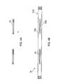
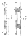
- the process of making the hollow composite structure 1 is described below with reference to Figures 4A to 4F .
- a composite stack 13 is produced by adding layers L2, L3 to a first layer L1, where the subsequent layers L2, L3 are laid up in the same way as illustrated and described with reference to Figure 2B .
- the abutting edges of the first portion 9A of each tile 9 are offset from the abutting edges of the first portion 9A of each tile 9 in adjacent layers such that any weakness due to the abutting joints is minimised.
- three layers L1, L2, L3 are shown for illustrative purposes.
- FIGs 3A and 3B illustrate alternative sequences of lay-up.
- each subsequent layer is laid offset to the right of the previous layer such that the joints between each tile do not overlap.
- the layers L1, L2, L3 are arranged such that the joints in the first and third layers L1, L3 are aligned, but the second layer L2 is sandwiched between the first and third layers L1, L3 and is also offset relative to the first and third layers L21, L3 such that the joints between tiles 9 in the first and second layers L1, L2 are offset from each other and the joints between tiles 9 in the second and third layers L2, L3 are offset from each other.
- Figures 4A to 4F illustrate the process of producing a three dimensional hollow composite structure 1 (see Figure 1 and Figure 5A ) from the substantially two-dimensional stack 13 of composite plies as illustrated in Figure 4A .
- the composite stack 13 can be laid up manually or by an automated process.
- each ply is stacked and arranged in a manner that will determine the material properties of the final product.
- the illustrated example shows three layers to indicate how the process changes the product from a flat stack to a three-dimensional structure at the end of the forming process. After lay-up is complete the stack of composite plies 13 is consolidated to remove air and to compact the stack.
- Figure 4B shows the next stage in the forming process, where the composite stack 13 is placed between two diaphragms 15A, 15B.
- the diaphragms 15A, 15B may be made of nylon bagging film that has high elongation properties.
- An example of a suitable material is the product known as DP1000, which is an example of nylon bagging film known under the Registered Trademark IPPLON®.
- DP1000 is capable of four hundred and fifty percent elongation before breaking at a maximum use temperature in the region of 204 - 212°C.
- Figure 4B also shows that the diaphragms 15A, 15B are sealed to form a closed bag.
- the closed bag may have one or more vacuum ports in it.
- the illustrated example includes a single vacuum port 17A.
- the arrangement illustrated in Figure 4B is hereinafter referred to as a diaphragm pack 19.
- FIG 4C is illustrative of the diaphragm pack 19 placed inside a double diaphragm forming (DDF) apparatus.
- the vacuum port 17A is connected such that a vacuum is applied between the two diaphragms 15A, 15B, where the air inside the diaphragm pack 19 is evacuated or substantially evacuated. Further vacuum ports 17B may be provided in the bed of the DDF apparatus.
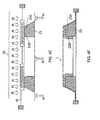
- the diaphragm pack 19 is placed upon a forming tool 23 about which the diaphragm pack 19 will deform to produce the end product.
- a set of arrows 25 is shown to represent heat applied from above within the DDF apparatus to commence the forming process, wherein the temperature of the resin in the composite stack 13 reaches a temperature at which the composite stack 13 can be formed into the shape of the forming tool 23.
- the forming tool 23 has an upper surface 23A against which the first portion 9A of the tiles 9 rests and a bore 23B that comprises a vertical wall.
- the forming tool 23 is configured such that the first portion 9A of the tiles 9 is supported and the second portion 9B of the tiles 9 is unsupported; the only support for the central region is provided by the diaphragm pack 19 until it is heated and until vacuum is applied.
- the diaphragm pack 19 When the composite stack 13 within the diaphragm pack 19 reaches the desired temperature the diaphragm pack 19 is lowered into contact with the forming tool 23. Heat application 25 is continued from above such that the composite stack 13 is maintained at a substantially constant forming temperature.
- the forming tool 23 may also provide a heat source (not shown) that directly heats the diaphragm pack 19, thus helping to maintain the diaphragm pack 19 at a constant temperature.
- the next stage of the forming process involves applying a vacuum Pv between the bottom diaphragm 15A, the forming tool 23 and the bed of the diaphragm forming apparatus, to evacuate air from the system and to draw the central region corresponding to the second portion 9B of the tiles 9 making up the composite stack 13 downwards into contact with the vertical wall of the forming tool 23.
- the outer periphery of the composite stack 13 that corresponds with the first portion 9A of the tiles 9 is drawn against the top surface 23A of the forming tool 23 to produce a three dimensional hollow composite structure 1.
- the forming process transfers the second portion 9B of each tile 9 from a horizontal to vertical orientation. During the process the overlap between the side edges of the second portions 9B of adjacent tiles 9 in the flat stack 13 is removed and the side edges of the second portions 9B of the tiles 9 move to substantially abut against side edges of adjacent tiles.
- the composite material making up the flat stack in the diaphragm pack comprises resin, which may be impregnated into the fibres making up the composite material or may be included between the tile layers. On heating the diaphragm pack the resin softens and enables the second portion of the tiles to slide relative to each other into contact with the internal surface of the forming tool and so as the edges of adjacent tiles move from overlapping to abutting against side edges of adjacent tiles. Alternatively it is possible to lay up dry fibres with the addition of a binder or tackifier. This flat stack is then formed as described above to create a dry preform. Liquid resin can be injected into the dry preform.
- the end product of the forming process illustrated and described with reference to Figures 4A to 4F is a hollow structure 1 that includes an integral flange 3.
- the end product produced by the process described above may be defined as a hollow composite structure 1 with double curvature.
- One element of the curvature C2 (see Figure 5A ) is defined by the circular periphery provided by the flange 3 and the second element of curvature C1 is the curve provided at the junction of the flange 3 with the cylindrical body 5.
- the curve C1 at the junction of the flange 3 with the cylindrical body 5 is due the thickness of the composite stack 13 that is being folded to produce the composite structure 1.
- each tile 9 comprises a single ply of composite material.
- each tile 9 may comprise unidirectional pre-impregnated material that contains for example aligned carbon fibres (examples of other suitable fibre types are described below).
- the use of unidirectional fibres offer the ability to place fibres in a component exactly where the reinforcement is required.
- the fibres may be arranged to provide reinforcement in the two principal directions of a cylindrical structure; namely, some are laid in a direction tangential (zero degree fibre direction) to the circle around which the tiles 9 are laid and adjacent plies may be laid with the fibres in the radial direction (ninety degree fibre direction).
- a dry unidirectional stitched non-crimped fabric could be used instead of a pre-impregnated unidirectional fibre.
- Resin can be introduced as a resin film interleaved between layers of fabric or as a liquid injected in a separate operation after forming the stack.
- suitable material are dry woven fabric only (produced by interlacing warp and weft fibres), dry woven fabric that is interleaved with resin film, or pre-impregnated woven fabric (where the fibres or the woven fabric is pre-impregnated with resin).
- Polymer matrix composites also known as fibre reinforced polymers are most suited to the method of production described above.
- Such materials use a polymer based resin as a matrix and a variety of fibres such as carbon, glass, or aramid as the reinforcement.
- the resin system for example epoxy or polyester
- reinforcing fibres such as carbon, aramid, glass or a combination of such reinforcements
- exceptional properties may be obtained.
- the properties of the resulting composite material combines the properties of the resin system with the properties of the reinforcement material.
- the geometry of the fibres is also important in producing a composite structure with the correct mechanical properties.
- Each of the tiles 9 described above is made of a composite material or fabric that may be defined as a manufactured assembly of long fibres of carbon, aramid, glass or a combination of these fibres that are held together for example by interlocking fibres (dry woven sheet) or with a secondary material to bind the fibres together (resin matrix). Hybrid fabrics that include more than one type of fibre may be used for the tiles.
- the reinforcement in each tile 9 may include carbon fibres only, aramid fibres only, glass fibres only. Alternatively, the reinforcement in each tile may combine two or more different reinforcement types to form each tile to produce a hybrid fabric. A combination of carbon and aramid fibres, glass and aramid fibres, carbon and glass fibres or a combination of carbon, aramid and glass fibres are examples of hybrid fabrics.
- FIG. 6 is a schematic representation of an aircraft 100 including first and second engines 102 and 104 housed in engine casings.
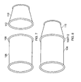
- Figure 7 is a schematic representation of an outer fan duct of a jet engine such as the engines 102 and 104 that comprises two sections, a first section 106 and a second section 110.
- the first section 106 is provided with a first flange 108 and the second section 110 is provided with a second flange 112.
- Figure 8 illustrates the first section 106 joined to the second section 110 at the flanges 108 and 112.
- Figure 9 illustrates this in more detail, in particular in the enlarged view, which shows the first flange 108 of the first section being joined to the second flange 112 of the second portion 110 by means of fastening members 114, which can, for example, be formed by bolts, rivets, etc.
- FIGS 10A and 10B are further representations of ducts for an aircraft engine which are examples of suitable application for the composite structure described above.
- Each of the ducts illustrated are divided into sections A1, which represent separate hollow structures joined together at the flange. Flanges are also used to attach the duct to other concentric hollow structures that fit around it. It is evident from Figures 10A and 10B that the ducts are not constructed from parallel cylinders and that some sections are barrelled and some are tapered. Therefore, although the embodiment described above relates to a circular shaped duct, it will be appreciated that the product made from the described method could have a shape other than circular with parallel walls.
- the duct could have an elliptical cross-section and/or the walls of the duct could be tapered or the walls of the duct could be barrel shaped.
- a barrel shaped body the side edges of the second portion 9B of the composite tiles 9 may be straight or curved.
- the shape of the side edges of the first 9A and second 9B portions of the tiles are determined by the final form of the hollow structure to ensure that side edges of the second portion 9B of adjacent tiles abut when formed into the duct section of the composite structure.
- Ducts and flanges having shapes other than curved may also be made by the method described above, for example, cross-sectional shapes that have angular edges for example hexagonal, octagonal etc. For such shapes the tile may have all straight edges.
Landscapes
- Engineering & Computer Science (AREA)
- Mechanical Engineering (AREA)
- Chemical & Material Sciences (AREA)
- Composite Materials (AREA)
- Combustion & Propulsion (AREA)
- Textile Engineering (AREA)
- General Engineering & Computer Science (AREA)
- Aviation & Aerospace Engineering (AREA)
- Manufacturing & Machinery (AREA)
- Transportation (AREA)
- Dispersion Chemistry (AREA)
- Physics & Mathematics (AREA)
- Health & Medical Sciences (AREA)
- Oral & Maxillofacial Surgery (AREA)
- Thermal Sciences (AREA)
- Moulding By Coating Moulds (AREA)
- Blow-Moulding Or Thermoforming Of Plastics Or The Like (AREA)
- Laminated Bodies (AREA)
Claims (13)
- Procédé de fabrication d'une structure composite comprenant un corps courbe (5) et une moulure intégrée (3) qui s'étend à partir d'une extrémité du corps courbe, le procédé comprenant les étapes suivantes:former un ensemble de diaphragme comprenant un empilement plat de couches composites (7) entre deux diaphragmes, dans lequel chaque couche de l'empilement plat est constituée d'une pluralité de tuiles composites (9), chaque tuile comprenant au moins une première partie (9A) et une deuxième partie (9B), des bords latéraux de la première partie étant configurés de manière à venir buter contre des bords latéraux de tuiles voisines, et des bords latéraux de la deuxième partie étant configurés de manière à chevaucher des bords latéraux de tuiles voisines;placer l'ensemble de diaphragme dans un dispositif de formage à double diaphragme (15A, 15B) comprenant un outil de formage en creux (23) qui prévoit une évacuation de l'air depuis l'intérieur de l'ensemble de diaphragme, dans lequel la première partie des tuiles composites est supportée sur une surface supérieure de l'outil;appliquer de la chaleur (25) à l'ensemble de diaphragme; etappliquer un vide (Pv) entre le diaphragme inférieur et l'outil de formage en creux, de telle sorte que:une région non supportée qui correspond à la deuxième partie des tuiles composites soit attirée en contact avec une paroi interne de l'outil de formage;les bords de la deuxième partie de tuiles voisines se déplacent afin de venir buter contre les bords latéraux de tuiles voisines;la première partie de chaque tuile forme une partie de la moulure; etla deuxième partie de chaque tuile forme une partie du corps courbe.
- Procédé selon la revendication 1, dans lequel les bords latéraux de la première partie de chaque tuile sont sensiblement radiaux.
- Procédé selon l'une quelconque des revendications 1 ou 2, dans lequel les bords latéraux de la deuxième partie de chaque tuile sont configurés avec des bords sensiblement parallèles.
- Procédé selon la revendication 2 ou 3, dans lequel les tuiles sont disposées en un motif circulaire.
- Procédé selon la revendication 2, 3 ou 4, dans lequel les bords de tuiles voisines dans chaque couche sont décalés par rapport aux bords de tuiles voisines dans des couches adjacentes.
- Procédé selon l'une quelconque des revendications précédentes, dans lequel chacune des tuiles disposées présente sensiblement la même forme et la même taille.
- Procédé selon l'une quelconque des revendications précédentes, dans lequel chaque tuile comprend une couche de matériau composite.
- Procédé selon la revendication 7, dans lequel les tuiles comprennent un matériau composite pré-imprégné unidirectionnel.
- Procédé selon la revendication 7, dans lequel les tuiles comprennent un matériau pré-imprégné tissé.
- Procédé selon la revendication 7, dans lequel les tuiles comprennent un tissu sec.
- Procédé selon la revendication 10, dans lequel le tissu sec est un tissu tissé ou un tissu non frisé piqué unidirectionnel qui comprend un agent liant ou un agent collant.
- Procédé selon la revendication 10 ou 11, dans lequel chaque couche de tissu sec lorsqu'elle est déposée pour former un empilement composite est entrelacée avec un film de résine.
- Procédé selon les revendications 7 à 12, dans lequel le matériau composite comprend des fibres de carbone et/ou des fibres d'aramide et/ou des fibres de verre.
Applications Claiming Priority (2)
| Application Number | Priority Date | Filing Date | Title |
|---|---|---|---|
| GB0716872A GB2452298B (en) | 2007-08-30 | 2007-08-30 | Composite structure |
| PCT/GB2008/002924 WO2009027684A1 (fr) | 2007-08-30 | 2008-08-29 | Structure composite et procédé d'obtention associé |
Publications (2)
| Publication Number | Publication Date |
|---|---|
| EP2195157A1 EP2195157A1 (fr) | 2010-06-16 |
| EP2195157B1 true EP2195157B1 (fr) | 2012-09-26 |
Family
ID=38616999
Family Applications (1)
| Application Number | Title | Priority Date | Filing Date |
|---|---|---|---|
| EP08788471A Active EP2195157B1 (fr) | 2007-08-30 | 2008-08-29 | Structure composite et procédé d'obtention associé |
Country Status (7)
| Country | Link |
|---|---|
| US (1) | US8263200B2 (fr) |
| EP (1) | EP2195157B1 (fr) |
| JP (1) | JP5203459B2 (fr) |
| CN (1) | CN101795852B (fr) |
| ES (1) | ES2401388T3 (fr) |
| GB (1) | GB2452298B (fr) |
| WO (1) | WO2009027684A1 (fr) |
Cited By (1)
| Publication number | Priority date | Publication date | Assignee | Title |
|---|---|---|---|---|
| DE102013019806A1 (de) * | 2013-11-27 | 2015-05-28 | Daimler Ag | Verfahren zum Umformen eines zweidimensionalen Faserhalbzeugs |
Families Citing this family (31)
| Publication number | Priority date | Publication date | Assignee | Title |
|---|---|---|---|---|
| DE102010015199B9 (de) * | 2010-04-16 | 2013-08-01 | Compositence Gmbh | Faserführungsvorrichtung und Vorrichtung zum Aufbau eines dreidimensionalen Vorformlings |
| DE102010031886A1 (de) * | 2010-07-14 | 2012-01-19 | Technische Universität München | Verfahren zum Herstellen eines Bauteils aus einem Faserverbundwerkstoff, Vorformling dafür sowie Bauteil |
| GB2484350B (en) * | 2010-10-08 | 2013-06-05 | Gkn Aerospace Services Ltd | Advanced fibre placement lay-up |
| GB2484349B (en) * | 2010-10-08 | 2012-12-05 | Gkn Aerospace Services Ltd | Sinusoidal flange |
| GB2484476B (en) * | 2010-10-11 | 2012-12-12 | Gkn Aerospace Services Ltd | Composite structure |
| GB2486231B (en) | 2010-12-07 | 2013-04-03 | Gkn Aerospace Services Ltd | Composite structure |
| DE102011100640A1 (de) | 2011-05-05 | 2012-11-08 | Compositence Gmbh | Verfahren und Vorrichtung zum Herstellen von Fasergelegen und Bauteilvorformlingen aus Fasern |
| FR2977826B1 (fr) * | 2011-07-11 | 2017-01-13 | Airbus Operations Sas | Procede de realisation d'un panneau avec une double courbure |
| US9777631B2 (en) | 2011-09-30 | 2017-10-03 | General Electric Company | Conformal inlet apparatus for a gas turbine engine |
| FR2982588B1 (fr) * | 2011-11-10 | 2013-11-22 | Aircelle Sa | Panneau composite a ecope de prelevement integree |
| US20130119191A1 (en) * | 2011-11-10 | 2013-05-16 | General Electric Company | Load-bearing structures for aircraft engines and processes therefor |
| DE102012007439A1 (de) | 2012-04-13 | 2013-10-17 | Compositence Gmbh | Legekopf und Vorrichtung und Verfahren zum Aufbau eines dreidimensionalen Vorformlings für ein Bauteil aus einem Faserverbundwerkstoff |
| EP2664446B1 (fr) | 2012-05-16 | 2015-04-29 | Airbus Operations GmbH | Procédé de fabrication d'un élément de garniture, élément de garniture et véhicule comportant une cabine et au moins un tel élément de garniture |
| GB201223032D0 (en) | 2012-12-20 | 2013-02-06 | Cytec Ind Inc | Method for forming shaped preform |
| JP6073499B2 (ja) | 2012-12-28 | 2017-02-01 | コンポジテンス ゲーエムベーハーCompositence GmbH | 二つのステップで三次元繊維ファブリック及び繊維製の構造部品プリフォームを製造するための方法及び装置 |
| DE102013220718A1 (de) * | 2013-10-14 | 2015-04-16 | Baier & Michels Gmbh & Co. Kg | Bauteil mit einem Befestigungsbereich für eine Schraubverbindung sowie Formteil und Befestigungsteil |
| FR3012527B1 (fr) * | 2013-10-30 | 2015-10-30 | Snecma | Metallisation d'un carter electriquement isolant d'un moteur aeronautique |
| US9796117B2 (en) * | 2014-06-03 | 2017-10-24 | Gkn Aerospace Services Structures Corporation | Apparatus for forming a flange |
| CN104369395A (zh) * | 2014-11-28 | 2015-02-25 | 沈阳飞机工业(集团)有限公司 | 含双曲面型面结构复合材料结构件的整体成型方法 |
| CN106541591B (zh) * | 2016-12-26 | 2019-01-11 | 河北科技大学 | 一种用于飞机机身成型过程中的中部承载装置 |
| CN106626429B (zh) * | 2016-12-26 | 2019-01-11 | 河北科技大学 | 一种用于飞机机身成型过程中的中部承载装置及其运动控制方法 |
| CA3073633A1 (fr) * | 2017-09-04 | 2019-03-07 | Lm Wind Power International Technology Ii Aps | Pale d'eolienne et methode de fabrication de pale d'eolienne |
| JP6719495B2 (ja) * | 2018-03-06 | 2020-07-08 | 株式会社Subaru | プリフォーム賦形方法、複合材成形方法及び複合材 |
| GB2572424B (en) * | 2018-03-29 | 2021-12-29 | Mclaren Automotive Ltd | Fibre flattening |
| GB201805320D0 (en) * | 2018-03-29 | 2018-05-16 | Mclaren Automotive Ltd | Diaphragm forming |
| CN110757830B (zh) * | 2018-07-26 | 2022-07-26 | 中国商用飞机有限责任公司 | 一种帽型长桁的热隔膜成型方法 |
| GB2615331A (en) * | 2022-02-03 | 2023-08-09 | Mclaren Automotive Ltd | Concavity diaphragm forming |
| US12447697B2 (en) | 2022-12-06 | 2025-10-21 | Rohr, Inc. | Forming duct structure with overbraided woven fiber sleeve |
| US12065966B2 (en) | 2022-12-06 | 2024-08-20 | Rohr, Inc. | Duct structure for aircraft propulsion system |
| US12194700B2 (en) | 2023-01-10 | 2025-01-14 | Rohr, Inc. | Forming duct structure with overbraided woven fiber sleeve |
| US12397512B2 (en) | 2023-01-10 | 2025-08-26 | Rohr, Inc. | Forming duct structure with overbraided woven fiber sleeve |
Family Cites Families (11)
| Publication number | Priority date | Publication date | Assignee | Title |
|---|---|---|---|---|
| FR1492415A (fr) * | 1965-08-25 | 1967-08-18 | Procédé et dispositif pour la fabrication d'un élément de construction obtenu par façonnage d'une plaque en matière synthétique et élément ainsi obtenu | |
| DE3117126C2 (de) | 1981-04-30 | 1985-01-10 | Messerschmitt-Bölkow-Blohm GmbH, 8000 München | Wellenkupplung mit einer elastischen Membran |
| GB8512243D0 (en) * | 1985-05-15 | 1985-06-19 | Ici Plc | Shaped articles |
| US5037599A (en) * | 1989-06-26 | 1991-08-06 | Basf Aktiengesellschaft | Single diaphragm forming of drapeable thermoplastic impregnated composite materials |
| GB8916909D0 (en) * | 1989-07-24 | 1989-09-06 | Ici Plc | Method of forming thermoformable composite material |
| US5348602A (en) * | 1993-06-08 | 1994-09-20 | General Electric Company | Method for making a bonded laminated article bend portion |
| US5648109A (en) * | 1995-05-03 | 1997-07-15 | Massachusetts Institute Of Technology | Apparatus for diaphragm forming |
| FR2763882B1 (fr) * | 1997-05-29 | 1999-08-20 | Aerospatiale | Outillage de reparation sur site d'une structure composite presentant une zone endommagee et procede correspondant |
| JP4070860B2 (ja) * | 1998-01-29 | 2008-04-02 | 富士重工業株式会社 | 複合材の成形方法および成形装置 |
| US8632653B2 (en) * | 2005-05-03 | 2014-01-21 | The Boeing Company | Method of manufacturing curved composite structural elements |
| JP2007253441A (ja) * | 2006-03-23 | 2007-10-04 | Shin Meiwa Ind Co Ltd | プリプレグ積層体の成形装置及び成形方法 |
-
2007
- 2007-08-30 GB GB0716872A patent/GB2452298B/en active Active
-
2008
- 2008-08-29 CN CN2008801050551A patent/CN101795852B/zh active Active
- 2008-08-29 EP EP08788471A patent/EP2195157B1/fr active Active
- 2008-08-29 WO PCT/GB2008/002924 patent/WO2009027684A1/fr not_active Ceased
- 2008-08-29 US US12/675,267 patent/US8263200B2/en active Active
- 2008-08-29 JP JP2010522439A patent/JP5203459B2/ja not_active Expired - Fee Related
- 2008-08-29 ES ES08788471T patent/ES2401388T3/es active Active
Cited By (2)
| Publication number | Priority date | Publication date | Assignee | Title |
|---|---|---|---|---|
| DE102013019806A1 (de) * | 2013-11-27 | 2015-05-28 | Daimler Ag | Verfahren zum Umformen eines zweidimensionalen Faserhalbzeugs |
| DE102013019806B4 (de) * | 2013-11-27 | 2015-06-03 | Daimler Ag | Verfahren zum Umformen eines zweidimensionalen Faserhalbzeugs |
Also Published As
| Publication number | Publication date |
|---|---|
| US8263200B2 (en) | 2012-09-11 |
| JP5203459B2 (ja) | 2013-06-05 |
| US20100206994A1 (en) | 2010-08-19 |
| JP2010538195A (ja) | 2010-12-09 |
| WO2009027684A1 (fr) | 2009-03-05 |
| GB0716872D0 (en) | 2007-10-10 |
| CN101795852B (zh) | 2013-06-19 |
| EP2195157A1 (fr) | 2010-06-16 |
| GB2452298A (en) | 2009-03-04 |
| CN101795852A (zh) | 2010-08-04 |
| ES2401388T3 (es) | 2013-04-19 |
| GB2452298B (en) | 2010-01-13 |
Similar Documents
| Publication | Publication Date | Title |
|---|---|---|
| EP2195157B1 (fr) | Structure composite et procédé d'obtention associé | |
| US7419627B2 (en) | Co-cured vacuum-assisted resin transfer molding manufacturing method | |
| EP3405332B1 (fr) | Fabrication de structures composites de forme complexe | |
| AU2020201610B2 (en) | Fabrication of composite laminates using temporarily stitched preforms | |
| US10596730B2 (en) | Hybrid lay-up mold | |
| EP2477799B1 (fr) | Procédé de moulage de parties composites complexes à l'aide d'un stratifié à fibre continue multidirectionnel préalablement assemblé | |
| KR101886877B1 (ko) | 직조 모재, 복합물 및 그 제조방법 | |
| CN102648080B (zh) | 编织预制件、复合材料、及其制造方法 | |
| EP0904929B1 (fr) | Méthode de fabrication d'un accessoire de conformage intra-moule directement lors du moulage | |
| WO2006136560A1 (fr) | Poutre de renfort, son procede de fabrication et stratifie de fibres utilise pour sa fabrication | |
| WO2009088029A1 (fr) | Base de fibre de renforcement de forme courbée, produit en couches l'employant, préforme, matériau composite de résine renforcé par une fibre et leurs procédés de fabrication | |
| JP5151668B2 (ja) | Frpの製造方法 | |
| US7374715B2 (en) | Co-cured resin transfer molding manufacturing method | |
| US10273829B2 (en) | Cylindrical case and manufacturing method of cylindrical case | |
| HK1064989B (en) | Co-cured vacuum-assisted resin transfer molding manufacturing method |
Legal Events
| Date | Code | Title | Description |
|---|---|---|---|
| PUAI | Public reference made under article 153(3) epc to a published international application that has entered the european phase |
Free format text: ORIGINAL CODE: 0009012 |
|
| 17P | Request for examination filed |
Effective date: 20100318 |
|
| AK | Designated contracting states |
Kind code of ref document: A1 Designated state(s): AT BE BG CH CY CZ DE DK EE ES FI FR GB GR HR HU IE IS IT LI LT LU LV MC MT NL NO PL PT RO SE SI SK TR |
|
| AX | Request for extension of the european patent |
Extension state: AL BA MK RS |
|
| DAX | Request for extension of the european patent (deleted) | ||
| 17Q | First examination report despatched |
Effective date: 20110207 |
|
| GRAP | Despatch of communication of intention to grant a patent |
Free format text: ORIGINAL CODE: EPIDOSNIGR1 |
|
| RTI1 | Title (correction) |
Free format text: COMPOSITE STRUCTURE AND RELETED METHOD TO OBTAIN IT |
|
| GRAS | Grant fee paid |
Free format text: ORIGINAL CODE: EPIDOSNIGR3 |
|
| GRAA | (expected) grant |
Free format text: ORIGINAL CODE: 0009210 |
|
| AK | Designated contracting states |
Kind code of ref document: B1 Designated state(s): AT BE BG CH CY CZ DE DK EE ES FI FR GB GR HR HU IE IS IT LI LT LU LV MC MT NL NO PL PT RO SE SI SK TR |
|
| REG | Reference to a national code |
Ref country code: GB Ref legal event code: FG4D |
|
| REG | Reference to a national code |
Ref country code: CH Ref legal event code: EP |
|
| REG | Reference to a national code |
Ref country code: AT Ref legal event code: REF Ref document number: 576828 Country of ref document: AT Kind code of ref document: T Effective date: 20121015 |
|
| REG | Reference to a national code |
Ref country code: IE Ref legal event code: FG4D |
|
| REG | Reference to a national code |
Ref country code: DE Ref legal event code: R096 Ref document number: 602008019040 Country of ref document: DE Effective date: 20121122 |
|
| REG | Reference to a national code |
Ref country code: SE Ref legal event code: TRGR |
|
| PG25 | Lapsed in a contracting state [announced via postgrant information from national office to epo] |
Ref country code: FI Free format text: LAPSE BECAUSE OF FAILURE TO SUBMIT A TRANSLATION OF THE DESCRIPTION OR TO PAY THE FEE WITHIN THE PRESCRIBED TIME-LIMIT Effective date: 20120926 Ref country code: HR Free format text: LAPSE BECAUSE OF FAILURE TO SUBMIT A TRANSLATION OF THE DESCRIPTION OR TO PAY THE FEE WITHIN THE PRESCRIBED TIME-LIMIT Effective date: 20120926 Ref country code: LT Free format text: LAPSE BECAUSE OF FAILURE TO SUBMIT A TRANSLATION OF THE DESCRIPTION OR TO PAY THE FEE WITHIN THE PRESCRIBED TIME-LIMIT Effective date: 20120926 Ref country code: NO Free format text: LAPSE BECAUSE OF FAILURE TO SUBMIT A TRANSLATION OF THE DESCRIPTION OR TO PAY THE FEE WITHIN THE PRESCRIBED TIME-LIMIT Effective date: 20121226 |
|
| REG | Reference to a national code |
Ref country code: LT Ref legal event code: MG4D Effective date: 20120926 |
|
| PG25 | Lapsed in a contracting state [announced via postgrant information from national office to epo] |
Ref country code: LV Free format text: LAPSE BECAUSE OF FAILURE TO SUBMIT A TRANSLATION OF THE DESCRIPTION OR TO PAY THE FEE WITHIN THE PRESCRIBED TIME-LIMIT Effective date: 20120926 Ref country code: GR Free format text: LAPSE BECAUSE OF FAILURE TO SUBMIT A TRANSLATION OF THE DESCRIPTION OR TO PAY THE FEE WITHIN THE PRESCRIBED TIME-LIMIT Effective date: 20121227 Ref country code: SI Free format text: LAPSE BECAUSE OF FAILURE TO SUBMIT A TRANSLATION OF THE DESCRIPTION OR TO PAY THE FEE WITHIN THE PRESCRIBED TIME-LIMIT Effective date: 20120926 |
|
| REG | Reference to a national code |
Ref country code: ES Ref legal event code: FG2A Ref document number: 2401388 Country of ref document: ES Kind code of ref document: T3 Effective date: 20130419 |
|
| PG25 | Lapsed in a contracting state [announced via postgrant information from national office to epo] |
Ref country code: IS Free format text: LAPSE BECAUSE OF FAILURE TO SUBMIT A TRANSLATION OF THE DESCRIPTION OR TO PAY THE FEE WITHIN THE PRESCRIBED TIME-LIMIT Effective date: 20130126 Ref country code: CZ Free format text: LAPSE BECAUSE OF FAILURE TO SUBMIT A TRANSLATION OF THE DESCRIPTION OR TO PAY THE FEE WITHIN THE PRESCRIBED TIME-LIMIT Effective date: 20120926 Ref country code: RO Free format text: LAPSE BECAUSE OF FAILURE TO SUBMIT A TRANSLATION OF THE DESCRIPTION OR TO PAY THE FEE WITHIN THE PRESCRIBED TIME-LIMIT Effective date: 20120926 Ref country code: EE Free format text: LAPSE BECAUSE OF FAILURE TO SUBMIT A TRANSLATION OF THE DESCRIPTION OR TO PAY THE FEE WITHIN THE PRESCRIBED TIME-LIMIT Effective date: 20120926 Ref country code: BE Free format text: LAPSE BECAUSE OF FAILURE TO SUBMIT A TRANSLATION OF THE DESCRIPTION OR TO PAY THE FEE WITHIN THE PRESCRIBED TIME-LIMIT Effective date: 20120926 |
|
| PG25 | Lapsed in a contracting state [announced via postgrant information from national office to epo] |
Ref country code: PL Free format text: LAPSE BECAUSE OF FAILURE TO SUBMIT A TRANSLATION OF THE DESCRIPTION OR TO PAY THE FEE WITHIN THE PRESCRIBED TIME-LIMIT Effective date: 20120926 Ref country code: PT Free format text: LAPSE BECAUSE OF FAILURE TO SUBMIT A TRANSLATION OF THE DESCRIPTION OR TO PAY THE FEE WITHIN THE PRESCRIBED TIME-LIMIT Effective date: 20130128 Ref country code: SK Free format text: LAPSE BECAUSE OF FAILURE TO SUBMIT A TRANSLATION OF THE DESCRIPTION OR TO PAY THE FEE WITHIN THE PRESCRIBED TIME-LIMIT Effective date: 20120926 |
|
| PG25 | Lapsed in a contracting state [announced via postgrant information from national office to epo] |
Ref country code: DK Free format text: LAPSE BECAUSE OF FAILURE TO SUBMIT A TRANSLATION OF THE DESCRIPTION OR TO PAY THE FEE WITHIN THE PRESCRIBED TIME-LIMIT Effective date: 20120926 Ref country code: BG Free format text: LAPSE BECAUSE OF FAILURE TO SUBMIT A TRANSLATION OF THE DESCRIPTION OR TO PAY THE FEE WITHIN THE PRESCRIBED TIME-LIMIT Effective date: 20121226 |
|
| PLBE | No opposition filed within time limit |
Free format text: ORIGINAL CODE: 0009261 |
|
| STAA | Information on the status of an ep patent application or granted ep patent |
Free format text: STATUS: NO OPPOSITION FILED WITHIN TIME LIMIT |
|
| PG25 | Lapsed in a contracting state [announced via postgrant information from national office to epo] |
Ref country code: IT Free format text: LAPSE BECAUSE OF FAILURE TO SUBMIT A TRANSLATION OF THE DESCRIPTION OR TO PAY THE FEE WITHIN THE PRESCRIBED TIME-LIMIT Effective date: 20120926 |
|
| 26N | No opposition filed |
Effective date: 20130627 |
|
| REG | Reference to a national code |
Ref country code: DE Ref legal event code: R097 Ref document number: 602008019040 Country of ref document: DE Effective date: 20130627 |
|
| PG25 | Lapsed in a contracting state [announced via postgrant information from national office to epo] |
Ref country code: CY Free format text: LAPSE BECAUSE OF FAILURE TO SUBMIT A TRANSLATION OF THE DESCRIPTION OR TO PAY THE FEE WITHIN THE PRESCRIBED TIME-LIMIT Effective date: 20120926 |
|
| REG | Reference to a national code |
Ref country code: CH Ref legal event code: PL |
|
| GBPC | Gb: european patent ceased through non-payment of renewal fee |
Effective date: 20130829 |
|
| PG25 | Lapsed in a contracting state [announced via postgrant information from national office to epo] |
Ref country code: MC Free format text: LAPSE BECAUSE OF FAILURE TO SUBMIT A TRANSLATION OF THE DESCRIPTION OR TO PAY THE FEE WITHIN THE PRESCRIBED TIME-LIMIT Effective date: 20120926 Ref country code: CH Free format text: LAPSE BECAUSE OF NON-PAYMENT OF DUE FEES Effective date: 20130831 Ref country code: LI Free format text: LAPSE BECAUSE OF NON-PAYMENT OF DUE FEES Effective date: 20130831 |
|
| REG | Reference to a national code |
Ref country code: IE Ref legal event code: MM4A |
|
| PG25 | Lapsed in a contracting state [announced via postgrant information from national office to epo] |
Ref country code: GB Free format text: LAPSE BECAUSE OF NON-PAYMENT OF DUE FEES Effective date: 20130829 Ref country code: IE Free format text: LAPSE BECAUSE OF NON-PAYMENT OF DUE FEES Effective date: 20130829 |
|
| PG25 | Lapsed in a contracting state [announced via postgrant information from national office to epo] |
Ref country code: MT Free format text: LAPSE BECAUSE OF FAILURE TO SUBMIT A TRANSLATION OF THE DESCRIPTION OR TO PAY THE FEE WITHIN THE PRESCRIBED TIME-LIMIT Effective date: 20120926 |
|
| PG25 | Lapsed in a contracting state [announced via postgrant information from national office to epo] |
Ref country code: LU Free format text: LAPSE BECAUSE OF NON-PAYMENT OF DUE FEES Effective date: 20130829 Ref country code: HU Free format text: LAPSE BECAUSE OF FAILURE TO SUBMIT A TRANSLATION OF THE DESCRIPTION OR TO PAY THE FEE WITHIN THE PRESCRIBED TIME-LIMIT; INVALID AB INITIO Effective date: 20080829 |
|
| REG | Reference to a national code |
Ref country code: FR Ref legal event code: PLFP Year of fee payment: 9 |
|
| PGFP | Annual fee paid to national office [announced via postgrant information from national office to epo] |
Ref country code: NL Payment date: 20160810 Year of fee payment: 9 |
|
| PGFP | Annual fee paid to national office [announced via postgrant information from national office to epo] |
Ref country code: AT Payment date: 20160725 Year of fee payment: 9 Ref country code: SE Payment date: 20160811 Year of fee payment: 9 |
|
| PGFP | Annual fee paid to national office [announced via postgrant information from national office to epo] |
Ref country code: ES Payment date: 20160712 Year of fee payment: 9 Ref country code: TR Payment date: 20160720 Year of fee payment: 9 |
|
| REG | Reference to a national code |
Ref country code: FR Ref legal event code: PLFP Year of fee payment: 10 |
|
| REG | Reference to a national code |
Ref country code: NL Ref legal event code: MM Effective date: 20170901 |
|
| REG | Reference to a national code |
Ref country code: AT Ref legal event code: MM01 Ref document number: 576828 Country of ref document: AT Kind code of ref document: T Effective date: 20170829 |
|
| PG25 | Lapsed in a contracting state [announced via postgrant information from national office to epo] |
Ref country code: SE Free format text: LAPSE BECAUSE OF NON-PAYMENT OF DUE FEES Effective date: 20170830 |
|
| PG25 | Lapsed in a contracting state [announced via postgrant information from national office to epo] |
Ref country code: AT Free format text: LAPSE BECAUSE OF NON-PAYMENT OF DUE FEES Effective date: 20170829 |
|
| PG25 | Lapsed in a contracting state [announced via postgrant information from national office to epo] |
Ref country code: NL Free format text: LAPSE BECAUSE OF NON-PAYMENT OF DUE FEES Effective date: 20170901 |
|
| REG | Reference to a national code |
Ref country code: FR Ref legal event code: PLFP Year of fee payment: 11 |
|
| REG | Reference to a national code |
Ref country code: ES Ref legal event code: FD2A Effective date: 20181025 |
|
| PG25 | Lapsed in a contracting state [announced via postgrant information from national office to epo] |
Ref country code: ES Free format text: LAPSE BECAUSE OF NON-PAYMENT OF DUE FEES Effective date: 20170830 |
|
| REG | Reference to a national code |
Ref country code: DE Ref legal event code: R082 Ref document number: 602008019040 Country of ref document: DE Representative=s name: KARO IP PATENTANWAELTE PARTG MBB, DE Ref country code: DE Ref legal event code: R082 Ref document number: 602008019040 Country of ref document: DE Ref country code: DE Ref legal event code: R082 Ref document number: 602008019040 Country of ref document: DE Representative=s name: KARO IP PATENTANWAELTE KAHLHOEFER ROESSLER KRE, DE |
|
| REG | Reference to a national code |
Ref country code: DE Ref legal event code: R082 Ref document number: 602008019040 Country of ref document: DE Representative=s name: KARO IP PATENTANWAELTE PARTG MBB, DE Ref country code: DE Ref legal event code: R082 Ref document number: 602008019040 Country of ref document: DE Representative=s name: KARO IP PATENTANWAELTE KAHLHOEFER ROESSLER KRE, DE |
|
| PG25 | Lapsed in a contracting state [announced via postgrant information from national office to epo] |
Ref country code: TR Free format text: LAPSE BECAUSE OF NON-PAYMENT OF DUE FEES Effective date: 20170829 |
|
| P01 | Opt-out of the competence of the unified patent court (upc) registered |
Effective date: 20230526 |
|
| PGFP | Annual fee paid to national office [announced via postgrant information from national office to epo] |
Ref country code: DE Payment date: 20250702 Year of fee payment: 18 |
|
| PGFP | Annual fee paid to national office [announced via postgrant information from national office to epo] |
Ref country code: FR Payment date: 20250703 Year of fee payment: 18 |