EP2195564B1 - Robinet mélangeur - Google Patents
Robinet mélangeur Download PDFInfo
- Publication number
- EP2195564B1 EP2195564B1 EP20080802690 EP08802690A EP2195564B1 EP 2195564 B1 EP2195564 B1 EP 2195564B1 EP 20080802690 EP20080802690 EP 20080802690 EP 08802690 A EP08802690 A EP 08802690A EP 2195564 B1 EP2195564 B1 EP 2195564B1
- Authority
- EP
- European Patent Office
- Prior art keywords
- valve
- mixing faucet
- rotational
- rotation
- rotational control
- Prior art date
- Legal status (The legal status is an assumption and is not a legal conclusion. Google has not performed a legal analysis and makes no representation as to the accuracy of the status listed.)
- Not-in-force
Links
- 238000002156 mixing Methods 0.000 title claims abstract description 48
- 230000033001 locomotion Effects 0.000 claims abstract description 54
- 239000007788 liquid Substances 0.000 claims abstract description 3
- 238000006073 displacement reaction Methods 0.000 claims description 15
- 230000005540 biological transmission Effects 0.000 claims description 13
- 238000010168 coupling process Methods 0.000 claims description 11
- 230000008878 coupling Effects 0.000 claims description 10
- 238000005859 coupling reaction Methods 0.000 claims description 10
- 239000000919 ceramic Substances 0.000 abstract description 4
- 230000008859 change Effects 0.000 description 14
- 238000006243 chemical reaction Methods 0.000 description 13
- 238000010276 construction Methods 0.000 description 7
- 238000013461 design Methods 0.000 description 7
- 230000008901 benefit Effects 0.000 description 4
- XLYOFNOQVPJJNP-UHFFFAOYSA-N water Substances O XLYOFNOQVPJJNP-UHFFFAOYSA-N 0.000 description 4
- 238000005516 engineering process Methods 0.000 description 3
- 230000002349 favourable effect Effects 0.000 description 3
- 238000013519 translation Methods 0.000 description 3
- 230000014616 translation Effects 0.000 description 3
- 239000004519 grease Substances 0.000 description 2
- 230000000149 penetrating effect Effects 0.000 description 2
- 239000000243 solution Substances 0.000 description 2
- 229910001369 Brass Inorganic materials 0.000 description 1
- 239000000853 adhesive Substances 0.000 description 1
- 230000001070 adhesive effect Effects 0.000 description 1
- 230000015572 biosynthetic process Effects 0.000 description 1
- 235000000332 black box Nutrition 0.000 description 1
- 244000085682 black box Species 0.000 description 1
- 239000010951 brass Substances 0.000 description 1
- 230000001419 dependent effect Effects 0.000 description 1
- 238000001514 detection method Methods 0.000 description 1
- 238000013038 hand mixing Methods 0.000 description 1
- 238000002347 injection Methods 0.000 description 1
- 239000007924 injection Substances 0.000 description 1
- 238000009434 installation Methods 0.000 description 1
- 230000007246 mechanism Effects 0.000 description 1
- 238000000034 method Methods 0.000 description 1
- 238000012986 modification Methods 0.000 description 1
- 230000004048 modification Effects 0.000 description 1
- 239000002991 molded plastic Substances 0.000 description 1
- 238000005457 optimization Methods 0.000 description 1
- 239000004033 plastic Substances 0.000 description 1
- 230000008569 process Effects 0.000 description 1
- 230000009467 reduction Effects 0.000 description 1
- 238000007789 sealing Methods 0.000 description 1
- 238000000926 separation method Methods 0.000 description 1
- 230000000087 stabilizing effect Effects 0.000 description 1
- 229910001220 stainless steel Inorganic materials 0.000 description 1
- 239000010935 stainless steel Substances 0.000 description 1
Images

Classifications
-
- F—MECHANICAL ENGINEERING; LIGHTING; HEATING; WEAPONS; BLASTING
- F16—ENGINEERING ELEMENTS AND UNITS; GENERAL MEASURES FOR PRODUCING AND MAINTAINING EFFECTIVE FUNCTIONING OF MACHINES OR INSTALLATIONS; THERMAL INSULATION IN GENERAL
- F16K—VALVES; TAPS; COCKS; ACTUATING-FLOATS; DEVICES FOR VENTING OR AERATING
- F16K11/00—Multiple-way valves, e.g. mixing valves; Pipe fittings incorporating such valves
- F16K11/02—Multiple-way valves, e.g. mixing valves; Pipe fittings incorporating such valves with all movable sealing faces moving as one unit
- F16K11/06—Multiple-way valves, e.g. mixing valves; Pipe fittings incorporating such valves with all movable sealing faces moving as one unit comprising only sliding valves, i.e. sliding closure elements
- F16K11/065—Multiple-way valves, e.g. mixing valves; Pipe fittings incorporating such valves with all movable sealing faces moving as one unit comprising only sliding valves, i.e. sliding closure elements with linearly sliding closure members
- F16K11/0655—Multiple-way valves, e.g. mixing valves; Pipe fittings incorporating such valves with all movable sealing faces moving as one unit comprising only sliding valves, i.e. sliding closure elements with linearly sliding closure members with flat slides
-
- F—MECHANICAL ENGINEERING; LIGHTING; HEATING; WEAPONS; BLASTING
- F16—ENGINEERING ELEMENTS AND UNITS; GENERAL MEASURES FOR PRODUCING AND MAINTAINING EFFECTIVE FUNCTIONING OF MACHINES OR INSTALLATIONS; THERMAL INSULATION IN GENERAL
- F16K—VALVES; TAPS; COCKS; ACTUATING-FLOATS; DEVICES FOR VENTING OR AERATING
- F16K31/00—Actuating devices; Operating means; Releasing devices
- F16K31/44—Mechanical actuating means
- F16K31/52—Mechanical actuating means with crank, eccentric, or cam
- F16K31/528—Mechanical actuating means with crank, eccentric, or cam with pin and slot
- F16K31/5286—Mechanical actuating means with crank, eccentric, or cam with pin and slot comprising a sliding valve
-
- Y—GENERAL TAGGING OF NEW TECHNOLOGICAL DEVELOPMENTS; GENERAL TAGGING OF CROSS-SECTIONAL TECHNOLOGIES SPANNING OVER SEVERAL SECTIONS OF THE IPC; TECHNICAL SUBJECTS COVERED BY FORMER USPC CROSS-REFERENCE ART COLLECTIONS [XRACs] AND DIGESTS
- Y10—TECHNICAL SUBJECTS COVERED BY FORMER USPC
- Y10T—TECHNICAL SUBJECTS COVERED BY FORMER US CLASSIFICATION
- Y10T137/00—Fluid handling
- Y10T137/8593—Systems
- Y10T137/86493—Multi-way valve unit
- Y10T137/86815—Multiple inlet with single outlet
- Y10T137/86823—Rotary valve
Definitions
- the invention relates to a mixer for two liquids of different temperature according to the preamble of claim 1.
- WO 99/02906 discloses a one-hand operation of a mixer tap to control the magnitude or temperature of an exiting volumetric flow.
- Faucets are known with two turntables that provide two each entering a closing valve or a closing valve and a mixing valve volume flows whose axes of rotation form an angle between 60 ° and 120 ° or spaced from each other.
- Disadvantage of these mixers is that size and temperature of the exiting flow can be adjusted only combined by two gripping movements, both movements allow a sensitive adjustment. This is achieved by simple, uniaxial rotary movements with angles of rotation of up to more than 360 ° - according to experience the best, because known the safest manageable adjusting movement - achieved.
- mixer taps are known with an actuator which is movable in two degrees of freedom.
- lever mixers eg: DE3411447A1 . DE2324364A
- lever actuator as a rotary-tilt plate with two degrees of freedom, in which initially to set the size of the exiting flow, the longitudinal movement of a rotatable control piston has been translated into a vertical tilting movement of the lever.
- lever mixers only tilt angle of less than 30 ° and rotation angle of less than 120 ° can be realized, which is ergonomically insufficient.
- the combination of two per se simple turning or tilting movements on the same actuator leads to an unpredictable and hardly manageable three-dimensional movement, which is intuitively not controllable in the short-term operation.
- the adjusting movement has to be corrected later and, according to experience, broken down into the two basic movements, the clean separation rarely succeeding. It has been shown that the two are independent of manipulated variables size and temperature of the exiting flow with a combined turn-tilt movement practically for over 90% of people are not accurately adjustable. Unintentional adjustment, such as opening the valve, is easily possible by simply bumping against the lever actuator, which can lead to scalding inconveniently.
- Thermostatic mixer (eg: DE3118003A1 . DE10044684A1 . EP0242680A2 ) offer two uniaxial turntable, although allow rotation angle of 180 ° for the size and 360 ° for the temperature of the exiting flow, but are arranged in an ergonomically unfavorable manner with opposite access direction widely spaced. This requires two gripping movements and opposite rotational movements, thereby precluding convenient one-hand operation.
- Built-in thermostatic mixer ( DE10048041A1 ) for partial wall mounting are provided with two coaxial, successively arranged turntables, wherein rotation angle of about 360 ° (for the temperature) and scarce 90 ° (for the size of the exiting flow) from two at least close to each other lying access directions are adjustable.
- Both adjusting movements can only be reached via two accesses, wherein the direction of access of the lever during the adjusting movement changes absolutely and above all relative to the direction of access of the front turntable.
- the invention has for its object to provide a mixer tap, which allows a goal-appropriate adjustment of the two target variables size and temperature of the exiting flow as directly as possible, comfortable, unique and independent of each other, while unintentional operations - by eg mere bumping - excludes basically creates the conditions for true one-hand operation in a permanent direction of access and uses proven valve technologies even with thermostatic mixers at low extra cost.
- This object is achieved according to the invention by a conversion gear.
- This conversion gear movement type position and / or size of the control variable in the first rotational control variable on a plane parallel to the sliding plate valve in particular parallel plane can be transferred.
- This change gear is so efficient that it easily without leverage only by means of two fingertips on each approximately opposite sides of the lateral surface of the turntable in substantially only one position supplied Hand alternatively allows the independent unique and safe adjustment of both rotational manipulated variables over the entire control range.
- the mixer tap transforms the simple and inexpensive conversion gearbox by a motion conversion, such.
- a motion conversion such.
- a predetermined by the valve technology degree of freedom of the control part of a perforated disc valve as a control variable in the ergonomically most favorable positioning movement and thereby enables the use of various proven valve technologies - such as ceramic perforated disc valve, thermostat controlled valve - whose construction, if necessary to be changed for optimization.
- the gearbox not only opens a simple possibility for translations of well over 2 in principle, but also creates the prerequisite for the two target variables temperature and size of the exiting volume flow in an ergonomically optimal movement position, in optimal movement, with optimal motion in the form of adjustment range and Actuating force independently of each other, d. H. intentionally unambiguous and accurate.
- the precondition is that both positioning movements are not coupled in any way.
- This concept according to the invention with one or more conversion gears allows constructions in which the uniaxial rotational movement which is ergonomically simplest and most precise can be achieved by means of two mutually approximately opposite sides of the opposite inverted, lever-free outer circumferential surfaces of the turntable fingertips for both Rotationsstellieren in ergonomically most favorable position is realized independently of each other.
- Each turntable has only one rotational degree of freedom compared to the stationary housing. Unintended operation is excluded in principle.
- the invariance allows access regardless of the current angular position of the turntable. That means access does not require a certain hand gesture. This is ease of use, because neither the detection of the current angular position of the turntable nor a corresponding adjustment of the hand position is required for access and condition for the easy change between two turntables.
- Invariance can be achieved by rotational symmetry to the axis of rotation. In the simplest case, this is a smooth cylinder with the axis of rotation as the axis of symmetry.
- the outer circumferential surfaces of the turntable be knurled in the axial direction, or be provided with longitudinal ribs of 1 to 2mm thickness and up to 3mm height or grooves of 1 to 2mm depth. They can be arranged so that the rotational symmetry of the turntable and thus their invariance against rotation about its axis of rotation is not limited or at least negligible for the hand position substantially.
- the invention allows a very compact, stable construction with both housing and turntable versions in thin stainless steel tube, as well as in brass or plastic.
- the adjusting movement of the fingertips of the supplied hand without arm movement and without substantial displacement of the hand is optionally switchable in one of the two rotational manipulated variables. This results in the most comfortable one-hand operation even when setting both rotational manipulated variables in one access. This is of particular interest in age-appropriate bathroom equipment, for example, to provide for a disability-friendly equipment of the sanitary area.
- the change gear in its overall form is designed as a circular disk which is arranged parallel to the sliding plane of the perforated disk valve, this results in the most compact structure in perfect cylindrical shape, since the central axis of the transmission can be selected to be identical with all axes of rotation of the turntable and rotational manipulated variables.
- the rotational manipulated variables are uniaxial rotations whose axes of rotation, in particular with the axis of rotation of the rotary actuator (s), are identical, the prerequisites for the simplest formal structure, namely in the basic form of an invariant cylinder with end-side access direction in the rotational axis direction, are created.
- the axes of rotation of the turntable to the axes of rotation of the rotational manipulated variables an angle> 0 ° - approximately in the range 30 ° - include. Then it's structurally easier if they intersect.
- the least effort to place - ie the most comfortable, ergonomic solution - is achieved by the fact that only two, three fingertips from always the same access direction on one or two rotationally symmetrical outer shell surfaces can be placed either independently of the current relative position of the turntable, then using the fingertips are rotatable without hand or even arm movement. The change is also done without hand and arm movement by slight displacement of the fingertips, either from outer lateral surface to outer lateral surface or with the outer lateral surface.
- the rotational manipulated variable for setting the size of the exiting volume flow from the direction of access is more direct, ie simpler and easier to adjust.
- This is achieved structurally in that the required torque for the position of the size of the volume flow is less than or at least not substantially greater than that of the rotational manipulated variable for setting the temperature, that a switchable rotary actuator is coupled to the rotational manipulated variable for setting the size of the volume flow as a permanent default or that with two turntables the one for setting the size upon access is reached first.
- the metering and mixing function is realized with a 2-disc perforated disc valve as a mixing valve, the two control variables, each with a rotational manipulated variable are almost independently adjustable.
- the temperature of the exiting volume flow can be set manually by way of a rotational manipulated variable by the ratio of the sizes of two volume flows of different temperature entering via the inlet bores into the mixing valve.
- thermostatic valve as a mixing valve by a thermostatic element after the - rotational manipulated variable for the temperature as a setpoint.
- thermostatic mixers are constructed with coaxial rotary plates same access direction with inner housing and housing, wherein the rotary setpoint for the temperature setpoint is stored in the inner housing, the Rotationsstellute for the size of the volume flow from the annular rotary plate, behind the end turntable for the Temperature is arranged, transfers to the perforated disc valve. This does not correspond to the ergonomic priority of the volume position, nor does it provide independent positioning movements.
- the ergonomically correct handling can be achieved by inner housing and housing partially penetrate.
- the housing is divided into an outermost part and an innermost part, in which the axis of rotation of the rotational manipulated variable for the temperature is fixedly mounted.
- the inner housing is arranged between these parts and provided with apertures, reach through the outermost part towards open struts of the innermost part to the support contact centering therethrough. Width of the struts, size of the breakthroughs and the number of both on the circumference are adjusted so that the inner housing relative to the two-part housing is rotatable about the maximum angle of rotation of the perforated disc valve.
- both rotational manipulated variables can each be directly and unambiguously provided with a generous, easily controllable uniaxial rotation without - implausible and aggravating - additional expenditure.
- the axis of rotation of the second turntable should be closely spaced, preferably parallel to the axis of rotation of the first turntable. The closer the turntables are arranged with an access direction, the more convenient the one-hand operation becomes. If their axes of rotation are identical, both turntables can be operated in just one access by one hand. If they are arranged directly behind one another, the fingertips are only slightly - moved by approximately 2 cm - essentially in the direction of its axis of rotation to switch to the desired turntable and thereby switch the rotational movement of the fingers in one of the two rotational manipulated variables. With end-side access in the direction of rotation axis this results in the ergonomically optimal structure.
- the turntables form over the adjusting movements substantially invariant rotation body.
- a gearbox as the invention implemented according to the conversion gearbox allows, for example via an exchange coupling, the switching of the rotational movement of the fingers on a turntable to the two rotational manipulated variables either.
- a turntable with an additional degree of freedom for switching between the two rotational manipulated variables naturally has a uniform access direction and also an identical axis of rotation for both actuating movements. It is directly accessible by the shortest route.
- the rotational manipulated variables are clearly to be set with a uniaxial rotation. However, only the first is in direct access and is a simple turn when, for example, a spring holds the turntable by default in the shift position for the first rotational manipulated variable.
- the setting of the second rotational manipulated variable requires a switching before the rotary movement and during the rotational movement, a holding force that must be superimposed on the actuating force.
- the simplest case for switching is a pushing movement in the direction of the axis of rotation - either by pushing or pulling.
- a pushing movement approximately orthogonal to the direction of the axis of rotation is possible as well as a pivoting or tilting movement of the turntable or a part of the mixer.
- friction clutch As a removable coupling friction or toothed couplings come as a radial, axial or conical couplings into consideration.
- Advantage of the friction clutch is the short switching path and easy coupling in each relative rotational position of the rotational control variables.
- Advantage of the toothed coupling is the lower holding force, which does not have to generate the required adhesive frictional force as a higher normal force, but only has to overcome the switching spring and the safe torque transmission after completion of the coupling process.
- the angle of rotation of about 90 ° of the movable perforated disc can be translated by a planetary gear that can be placed entirely within the turntable in the input via bridge or ring gear in the rotational manipulated variable on the sun gear, with the Turntable with identical rotation axis rotatably connected.
- the high torque of the control variable due to seals and sealing grease and at the same time their low rotation angle can be converted into an ergonomically comfortable positioning movement with more than 3 times the ratio.
- a 2-disc perforated disc valve as mixing valve made of ceramic whose at least first control variable displacement of a first movable perforated disc of the perforated disc valve in particular a hole with respect to a second with her in a contact surface in Surface contact arranged, fixed in the housing and provided with two inlet bores and in particular a drain hole perforated disc.
- a second control variable may be a degree of freedom of a third perforated disk of the perforated disk valve which is movable in contact with the first perforated disk and / or second perforated disk in its contact surface, preferably as a mixing valve.
- Easier is the use of two independent degrees of freedom of the first perforated disc with respect to the second perforated disc for the two control variables of the perforated disc valve as a particular mixing valve.
- a rotation or a second displacement orthogonal to the first displacement can be used as the second degree of freedom, whereby the size of the volume flow is not changed when setting the temperature, and vice versa.
- the target variables temperature and size can thus be determined independently of each other.
- the movable first perforated disc with a hole stands with the fixed in the housing second perforated disc with two inlet bores and an outlet hole in a contact surface in particular via a grease in surface contact.
- control part and the movable perforated plate can be identical.
- control variables be transmitted to the perforated disk via a control part which is in direct support contact with the movable perforated disk.
- a second control variable of the control part of a valve can be transmitted either by an additional degree of freedom of the first transmission or by a separate second transmission in the second rotational manipulated variable.
- a very elegant solution for a suitable planar change gear is a cam gear from a trained as a ring Spiralnutany and a slide whose backdrop is guided in the spiral guide groove, wherein the center of the spiral is advantageously arranged on the axis of rotation of Spiralnutany.
- the slider carries a driver, which engages in a groove of the control part whose length corresponds to its width and the displacement of the other degree of freedom.
- the perforation allows the passage of the driver of a second slider and / or the rotatable mounting of the cam on a shaft whose outer diameter corresponds to the hole diameter.
- the guide groove are replaced by a guide rib on the cam and the scenery by a groove in the slide.
- a cartridge connects valve and gearbox to form a unit. It reduces the noise emission through the air and gives all valve and gear members guidance and support.
- a slider in a groove of the cartridge can be moved and a cam with a perforation or sleeve on a shaft of the cartridge or with a shaft or its outer edge to be rotatably mounted in a bore of the cartridge or on the inside of a circular cartridge shell.
- the cartridge is also used for easy assembly when replacing the valve or gearbox.
- the second control variable of the perforated disc valve can be converted into the second rotational manipulated variable as a mixing valve or a second valve.
- the change gear in surface contact one above the other, it is a prerequisite that a change gear frame fixed passage, such. B. in a cam gear has a concentric with the axis of rotation of the cam hole, has to be able to pass the power transmission of the other.
- grooved disc and slide can be stacked alternately block-like. They give each other leadership and support. This results in the most compact, stable and, in the case of identical axes of rotation of the cams, in principle also the simplest construction, in which large parts of the change gear can be accommodated within the turntable.
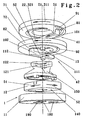
- Fig. 1 the mixer tap is shown in the usual external view.
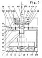
- the two cylindrical rotary actuators 31, 32 invariant with respect to their adjusting movements, each having a uniaxial, rotary degree of freedom 311, 321, are arranged directly above one another. Its direction of access 6 is the same and constant over the entire setting range. Their outer surfaces are knurled to ensure secure frictional engagement, even with soapy fingers.
- Their axes of rotation are identical to the central axis of the likewise cylindrical housing 170. This upright arrangement corresponds to the use of the mixer tap to sinks or sink. The grasping hand comes from the top parallel to the axes of rotation.
- the length of the housing 170 under the two turntables 31,32 is ergonomically advantageous between 45 and 200 mm.
- the advantageous outer diameter for both turntables 31,32 is between 25 and 50 mm. If the outer diameter of the housing 170 corresponds to those of the turntable 31,32, between 40 and 50 mm. Their height is advantageous depending on the diameter of 15 to 40 mm, to allow the operation in a handle of one hand safely.
- the mixer tap When using the mixer tap on showers or bathtubs, the mixer tap is rotated by 90 ° in a horizontal position, so that the two turntable 31,32 show forward to the user.
- the housing length behind the turntables 31,32 is then about 65 mm.
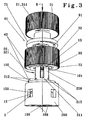
- the Fig. 2 shows in the lower part of a perforated disc mixing valve 1, consisting of a non-illustrated housing fixed first perforated disc 11, each with an inlet bore 180 for hot and cold water and an outlet bore 190 for the mixed water and arranged with it in a contact surface 140 in surface contact and in two mutually orthogonal translational degrees of freedom as control variables 51,52 with respect to their displaceable second perforated disc 12, which is connected by positive engagement with the control part 150.
- This has the one hand the task of redirecting the incoming cold and hot water flows by 180 °, on the other hand it carries two control grooves 121,122 whose Main extension direction corresponds to one of the two control variables 51,52, for receiving the driver 111,112.
- two cam disk drives are stacked as a planar change gear 41, 42 in surface contact in a block-like manner. Support their limbs and thereby lead each other.
- a slide 101,102 arranged, which is guided with its backdrop 81.82 in the spiral guide groove 91.92 on the underside of the grooved disc.
- the two cam disk drives convert the two mutually orthogonal displacements prescribed by the valve design as control variables 51, 52 of the perforated disk 12 into uniaxial rotations of the cam disks 71, 72 with limited torque and generous adjustment angle as rotational manipulated variables 21, 22.
- the axes of rotation of the two cam disks 71, 72 are identical, centered on their outer lateral surfaces and normal to the contact surface 140 of the two perforated disks 11, 12.
- the driver 111 of the upper conversion gear 41 protrudes through the passage 13 of the cam 72 of the lower conversion gear 42 into the control groove 122 of the control part 150.
- the passage 13 is a circular, central, concentric with the axis of rotation of the cam 72 perforation, the displacement of the control variable 51 of the upper slide 101 granted sufficient clearance and is fixed to the frame, since its central axis is identical to the axis of rotation of the lower cam 72nd
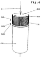
- Fig. 3 discloses the relationship between the two turntable 31,32 with the same direction of access 6 and the two converters 41,42 and shows the fixed frame cartridge 200, which determines the relative position of all members of the gearbox 41.42 and the first perforated disc of the perforated disc mixing valve 1, not shown , It itself is fixed in the housing, not shown, and carries in its bottom two inlet bores 180 for the incoming hot and cold volume flows and an outlet bore 190 for the mixed flow.
- Its lower part is designed as a virtually closed cylinder, which surrounds the perforated disc mixing valve 1 and the control part 150.
- the upper end of this cylinder carries a groove 212 for receiving and guiding the slider 102 of the lower transaxle 42 in the direction of its displacement as a control variable 52nd
- the cartridge 200 continues in a neck of circular cross-section, which is interrupted by a further groove 211 for receiving and guiding the slider 101 of the upper conversion gear 41 in the direction of its displacement as a control variable 51.
- the neck forms a common shaft 220, on both cams 71,72 and thus the two with them in pairs rotatably connected rotary actuator 31,32 are rotatably mounted in their degrees of freedom 311,321.
- both the axes of rotation of both turntables 31,32 and both cam 71,72 and thus the rotational manipulated variables 21,22 are identical.
- the degrees of freedom 311, 311 of the turntables 31, 32 are also those of the cam disks 71, 72 as rotation manipulated variables 21, 22 and, in this exemplary embodiment, identical.
- the entire transmission 41 and a large part of the conversion gear 42 can be accommodated in a simple manner and mutually guiding and stabilizing within the turntable 32.
- the mixer is a true single-handed thermostatic mixer with thermostatic valve 2 as a mixing valve for controlling the control quantity for the mixing ratio of the incoming volumetric flows, which determines the temperature of the exiting volumetric flow at a predetermined by the Rotationsstelltechnik 22 setpoint and orifice valve 1 for controlling the size control variable 51 the exiting flow as a closing valve, which is set by the rotational manipulated variable 21.
- a gearbox as a conversion gear 41 By a gearbox as a conversion gear 41 are both rotational control variables 21,22 from a permanent access direction 6 in the access of one hand with only a single-axis turntable 31 adjustable.
- An additional translatory degree of freedom 312 in the direction of the axis of rotation of its first rotational degree of freedom 311 allows the addition of a radial change coupling 17,18, depending on the end 3121,3122 in its degree of freedom 312 in the rotation of its degree of freedom 311 either via the hollow shaft 35, planetary gear 29th and the inner housing 171 with the movable orifice plate 12 of the orifice plate valve 1 or via the rim 16, axis 152, screw thread 65 and push sleeve 66 with the actuator of the thermostatic control element 45 of the thermostatic valve 2 couples, whereby its rotational degree of freedom 311 corresponding to one or the other rotational manipulated variable 21:22 becomes.
- Inner housing 171 and housing 170 penetrate each other through the formation of apertures 64 and these penetrating struts 63.
- the housing 170 is in an outermost, closed part 62 and an innermost, 63 to open for supporting contact with the outermost part 62 open struts open Part 61, which are connected to each other rotationally and detachably, divided.
- the axis 152 for the rotational manipulated variable 22 and the thrust sleeve 66 are mounted in the innermost part 61.
- the inner housing 171 is disposed between these parts 61,62 and provided with apertures 64, through which the struts 63 of the innermost part 61 of the housing 170 to the outermost part 62nd centering and reach into support contact.
- the width of the struts 63 and the size of the apertures 64 is adjusted so that the inner housing 171 relative to the two-part housing 170 by the maximum control variable 51 as rotation angle of the movable perforated disk 12 of the perforated disk valve 1 of about 65 to 80 ° rotatable.
- the control variable 51 is via the inner housing 171 for rotation of the planet carrier 25.
- the ring gear 26 is fixed in the outermost part 62 of the housing 170.
- the resulting rotation of the sun gear 27 with limited torque and increased rotation angle of advantageously over 250 ° forms the rotational manipulated variable 21.
- the gear ratio is advantageously 1.6 to 4, recommended via 2nd change coupling 17,18 and the planetary gear 29 together form the transmission as a transmission 41st
- the changeover clutch 17,18 is held as a default in the end position 3121, so that the setting of the rotational control variable 21 is always directly, safely and practically “blind” automatically, without additional coupling operation is possible.
- the spring force is to be overcome by a compressive force in the direction of access 6 and maintain throughout the duration of the adjustment.
Landscapes
- Engineering & Computer Science (AREA)
- General Engineering & Computer Science (AREA)
- Mechanical Engineering (AREA)
- Multiple-Way Valves (AREA)
- Domestic Plumbing Installations (AREA)
Claims (15)
- Mélangeur pour deux liquides de températures différentes, consistant en une valve de mélange, une valve à plaque perforée (1) avec un paramètre de commande (51) déterminant le volume d'un débit de sortie, et au moins un dispositif de commande rotatif (31) monté avec un degré de liberté en rotation (311) par rapport à un boîtier fixe (170), dont fait partie un dispositif de commande rotatif (31) principalement invariable dans sa forme extérieure avec direction d'accès (6) sur la face avant, et par rotation duquel au moins une première de deux variables de commandes coaxiales en rotation (21,22) peut être réglée pour la commande du volume ou de la température d'un débit en sortie, caractérisé en ce que au moins un réducteur-convertisseur (41), par lequel le type de mouvement, la position et/ou le volume du paramètre de commande (51) est/sont convertible(s) dans la première variable de commande en rotation (21) sur un plan en particulier parallèle au plan de glissement de la valve à plaque perforée.
- Mélangeur selon la revendication 1, caractérisé en ce que en particulier le réducteur-convertisseur plat (41) est formé substantiellement en symétrie par rotation par rapport à son axe d'entraînement en tant qu'axe de rotation de la variable de commande en rotation (21) de préférence dans sa forme entière en tant que plaque circulaire.
- Mélangeur selon l'une des revendications 1 ou 2 caractérisé en ce que, le mélangeur forme un mélangeur à commande unique dans lequel chacune des variables de commande en rotation (21, 22) peut être réglée de manière sélective de préférence dans une position substantiellement manuelle après un seul accès d'une seule main, en particulier dans la direction d'accès permanente (6).
- Mélangeur selon l'une des revendications 1 à 3, caractérisé en ce qu'au moins une, en particulier chacune des deux variables de commande en rotation (21, 22) peut être réglée de manière sélective au moyen de deux coupelles pour les doigts situées sur des côtés approximativement opposés de la surface de l'enveloppe extérieure des dispositifs de commande rotatifs (31) de sorte que chacune des variables de commande en rotation (21, 22) peut être réglée de manière sélective par une main qui demeure dans une position de préférence permanente sur toute la plage de réglage, particulièrement dans la direction d'accès (6).
- Mélangeur selon l'une des revendications 1 bis 4, caractérisé en ce que la variable de commande en rotation (22) destinée à régler le volume du débit en sortie est réglable de manière plus directe à partir de la direction d'accès (6), en particulier par le dispositif de commande rotatif (31) situé à l'extrémité, et avec un couple qui n'est pas substantiellement plus important que celui qui est nécessaire à la variable de commande en rotation (21) pour régler la température.
- Mélangeur selon l'une des revendications 1 bis 5, caractérisé en ce que la valve à plaque perforée (1) est la valve de mélange et que le rapports de deux débits entrant dans la valve de mélange par les trous d'arrivée (180) est réglable manuellement au moyen de la variable de commande en rotation (22).
- Mélangeur selon l'une des revendications 1 à 5, caractérisé en ce que la valve à plaque perforée (1) est une valve de fermeture et que la température du débit de sortie est contrôlée en tant que valeur de consigne par une valve à thermostat (2) en tant que valve de mélange selon la variable de commande en rotation (22).
- Mélangeur selon la revendication 7, caractérisé en ce que, le mélangeur comprend le boîtier (170) et un boîtier intérieur (171) qui s'interpénètrent partiellement en formant des montants (63) et des passages (64) et que le boîtier (170) est en particulier une structure en deux parties, une partie intérieure (61) et une partie extérieure (62) entre lesquelles est agencée au moins une partie du boîtier intérieur (171).
- Mélangeur selon l'une des revendications 1 à 8, caractérisé par un second dispositif de réglage rotatif (32) monté avec un degré de liberté en rotation (321), principalement symétrique par rotation par rapport à son axe de rotation, principalement avec la même direction d'accès (6), à laide duquel la deuxième variable de commande en rotation (22) est réglable par son degré de liberté (321), à laquelle occasion le mouvement de réglage des coupelles de doigts de la main qui accède peut de préférence commuter de manière sélective sur au moins pratiquement chacune des positions relatives de rotation des deux dispositifs de commande rotatifs (31,32), d'un dispositif de commande rotatif sur l'autre (31,32), en particulier par déplacement des coupelles dans l'une des variables de commande en rotation (21,22).
- Mélangeur selon l'une des revendications 1 à 8, caractérisé en ce que le réducteur-convertisseur (41) est un réducteur de commande en particulier avec un accouplement interchangeable (17,18), par lequel il est possible d'activer de manière sélective la rotation du dispositif de commande rotatif (31), de préférence par déplacement axial du dispositif de commande rotatif (31), par rapport à l'une des variables de commande en rotation (21,22).
- Mélangeur selon l'une des revendications 1 à 10, caractérisé en ce qu'il dispose, en tant que réducteur-convertisseur (41), d'un réducteur planétaire, agencé au moins en grande partie de préférence à l'intérieur du dispositif de commande rotatif (31), et dont la roue solaire (27) est connectable de manière résistante à la torsion par un axe de rotation en particulier identique au dispositif de commande rotatif (31).
- Mélangeur selon l'une des revendications 1 à 11, caractérisé par deux paramètres de commande (51,52), qui sont des degrés de liberté indépendants l'un de l'autre, de préférence des déplacement orthogonaux de la première plaque perforée mobile (12) par rapport à une seconde plaque perforée (11) de la valve à plaque perforée (1) en particulier en tant que valve de mélange.
- Mélangeur selon la revendication 12, caractérisé par un deuxième réducteur-convertisseur en particulier plat (42), avec lequel la deuxième quantité de commande (52) de la valve à plaque perforée (1) en tant que valve de mélange ou d'une seconde valve est convertible en seconde variable de commande en rotation (22).
- Mélangeur selon l'une des revendications 1 à 13, caractérisé en ce qu'au moins un réducteur-convertisseur (41,42) est un réducteur à came qui est constitué en particulier par une plaque à rainure en tant que came (71,72) et par un tiroir (101, 102) muni d'un coulisseau (81,82) guidé dans une rainure de guidage (91,92), qui est logé de préférence dans une rainure (211,212) d'une cartouche (200) dans la direction du déplacement en tant que quantité de commande (51,52) et pénètre en particulier avec un entraîneur (111,112) dans une rainure de commande (121,122), et qui est en contact portant avec la plaque perforée (12) de préférence par le biais d'une pièce de commande (150).
- Mélangeur selon l'une des revendications 13 ou 14, caractérisé en ce que deux réducteurs-convertisseurs (41, 42) en particulier plats sont superposés en contact superficiel, réducteurs-convertisseurs dont au moins un second réducteur-convertisseur (42) laisse ouvert un passage permanent (13) pour la transmission des forces du premier réducteur-convertisseur (41), le disque de came (71,72) en particulier dans un réducteur à came étant doté d'un trou central et formé en anneau et, lorsqu'il y a deux réducteurs à came, les disques de cames (71, 72) et les tiroirs (101,102) étant chacun superposés alternativement avec de préférence des axes de rotation identiques de leurs cames (71,72).
Applications Claiming Priority (3)
| Application Number | Priority Date | Filing Date | Title |
|---|---|---|---|
| DE102007046136 | 2007-09-27 | ||
| DE102007046135 | 2007-09-27 | ||
| PCT/EP2008/008250 WO2009043562A1 (fr) | 2007-09-27 | 2008-09-28 | Robinet mélangeur |
Publications (2)
| Publication Number | Publication Date |
|---|---|
| EP2195564A1 EP2195564A1 (fr) | 2010-06-16 |
| EP2195564B1 true EP2195564B1 (fr) | 2011-05-25 |
Family
ID=40290960
Family Applications (1)
| Application Number | Title | Priority Date | Filing Date |
|---|---|---|---|
| EP20080802690 Not-in-force EP2195564B1 (fr) | 2007-09-27 | 2008-09-28 | Robinet mélangeur |
Country Status (5)
| Country | Link |
|---|---|
| US (1) | US8631823B2 (fr) |
| EP (1) | EP2195564B1 (fr) |
| CN (1) | CN101809347B (fr) |
| AT (1) | ATE511046T1 (fr) |
| WO (1) | WO2009043562A1 (fr) |
Cited By (1)
| Publication number | Priority date | Publication date | Assignee | Title |
|---|---|---|---|---|
| DE102017222196A1 (de) | 2017-12-07 | 2019-06-13 | Hansgrohe Se | Ventilbetätigungsvorrichtung und Sanitärventil |
Families Citing this family (14)
| Publication number | Priority date | Publication date | Assignee | Title |
|---|---|---|---|---|
| USD706391S1 (en) * | 2012-02-28 | 2014-06-03 | Eaton Corporation | Annular flux collector for a valve body |
| US9423046B2 (en) | 2012-02-28 | 2016-08-23 | Eaton Corporation | Flux collector with interconnected portions and method of manufacturing solenoid valve assembly having same |
| US9091357B2 (en) * | 2013-12-16 | 2015-07-28 | Kuching International Ltd. | Ceramic valve with intermediate section having cold water supply function |
| DE102014000840B3 (de) * | 2014-01-22 | 2015-03-12 | Hansa Metallwerke Ag | Sanitäres Mischventil |
| CN105673912B (zh) * | 2016-04-18 | 2018-12-18 | 陈非 | 一种触摸式恒温水龙头系统及其控制方法 |
| CN106764016B (zh) * | 2016-12-16 | 2017-11-07 | 王惟滨 | 一种水龙头外接调档机构 |
| CA3002824C (fr) | 2017-04-26 | 2022-08-23 | Delta Faucet Company | Interface utilisateur de robinet |
| US10247313B2 (en) * | 2017-06-29 | 2019-04-02 | Tao-Pao Chien | Spray gun and adjustment valve thereof |
| GB201808925D0 (en) * | 2018-05-31 | 2018-07-18 | Johnson Electric Sa | Multi-channel disc valve assembly |
| DE102019003301A1 (de) * | 2019-05-10 | 2020-11-12 | Grohe Ag | Einhebel-Kartusche für eine Sanitärarmatur |
| CN110924479B (zh) | 2019-11-08 | 2021-11-16 | 3M创新有限公司 | 一种龙头以及具有该龙头的过滤系统 |
| US11781662B2 (en) * | 2021-05-28 | 2023-10-10 | Hanon Systems Efp Deutschland Gmbh | Multi-port rotary actuated valve assembly |
| EP4404024A1 (fr) * | 2022-05-13 | 2024-07-24 | Ideal Standard International NV | Unité de réglage pour une cartouche thermostatique |
| DE102024109038A1 (de) * | 2024-03-28 | 2025-10-02 | Grohe Ag | Drucktastenventil für eine Sanitärarmatur |
Family Cites Families (26)
| Publication number | Priority date | Publication date | Assignee | Title |
|---|---|---|---|---|
| US2633872A (en) * | 1947-04-21 | 1953-04-07 | Vincent D Hennessey | Valve actuating mechanism and assemblage |
| US2601966A (en) * | 1947-09-23 | 1952-07-01 | Don K Busick | Fluid flow control |
| DE1198150B (de) | 1960-02-03 | 1965-08-05 | Alfred M Moen | Eingriffmischbatterie |
| FR1539008A (fr) * | 1967-05-19 | 1968-09-13 | Robinet mélangeur sanitaire | |
| US3511279A (en) * | 1968-04-17 | 1970-05-12 | Crosweller & Co Ltd W | Fluid mixing devices |
| US3667503A (en) * | 1970-06-05 | 1972-06-06 | Elkay Mfg Co | Single-handle mixing and proportioning valve |
| IL42027A (en) | 1972-05-17 | 1975-10-15 | Moen A | Faucet handle construction |
| FR2208499A5 (fr) * | 1972-11-29 | 1974-06-21 | Morisseau Bernard | |
| US4033373A (en) * | 1976-06-03 | 1977-07-05 | Masco Corporation Of Indiana | Single handle water faucet valve |
| DE2636517C3 (de) | 1976-08-13 | 1979-08-23 | Lorenz Dipl.-Ing. 1000 Berlin Claussen | Einhand-Mischbatterie |
| NL188243C (nl) | 1980-05-20 | 1992-05-06 | Anton Jakob Willi | Thermostatische menginrichting voor koud en warm water. |
| NO152880C (no) * | 1983-08-30 | 1985-12-04 | Lyng Ind As | Temperaturpaavirkbar, elektronisk styrt blandeventil for blanding av to vaesker. |
| DE3411447A1 (de) | 1984-03-28 | 1985-10-03 | Ideal-Standard Gmbh, 5300 Bonn | Sanitaere einhand-mischbatterie |
| DE3612988A1 (de) | 1986-04-17 | 1987-10-29 | Grohe Armaturen Friedrich | Mischbatterie |
| IT1238908B (it) * | 1990-04-24 | 1993-09-07 | Galatron Srl | Valvola miscelatrice di acqua calda e fredda con comandi indipendenti per l'erogazione dei due tipi di acqua |
| CN1244932A (zh) * | 1996-12-12 | 2000-02-16 | 美国标准公司 | 流体流量伺服控制用阀系统 |
| CN2312378Y (zh) * | 1997-05-14 | 1999-03-31 | 成哲基 | 一种冷热水排放装置 |
| AU3645897A (en) * | 1997-07-11 | 1999-02-08 | Frank J. Hennessy | Plumbing installation |
| US6491063B1 (en) * | 1997-09-17 | 2002-12-10 | Ben-Ro Industry And Development Ltd. | Valve assembly and airconditioning system including same |
| DE10044684A1 (de) | 2000-09-08 | 2002-03-21 | Grohe Armaturen Friedrich | Mischbatterie für Kalt- und Heißwasser |
| DE10048041B4 (de) * | 2000-09-29 | 2005-12-15 | Ideal-Standard Gmbh & Co. Ohg | Sanitäre Mischbatterie |
| DE10239177A1 (de) * | 2002-08-21 | 2004-03-04 | Grohe Water Technology Ag & Co. Kg | Mischbatterie |
| US6766827B2 (en) * | 2002-09-27 | 2004-07-27 | Kuching International Inc. | Core shaft of the control stick of a vertical type faucet |
| DE10347819A1 (de) * | 2003-10-10 | 2005-05-04 | Grohe Water Tech Ag & Co Kg | Mischbatterie |
| US7143786B2 (en) * | 2003-12-11 | 2006-12-05 | Newfrey Llc | Two-handle flow-through valve |
| GB0516264D0 (en) * | 2005-08-08 | 2005-09-14 | Hornbeam Ivy Ltd | Mixer tap |
-
2008
- 2008-09-28 EP EP20080802690 patent/EP2195564B1/fr not_active Not-in-force
- 2008-09-28 CN CN2008801089852A patent/CN101809347B/zh not_active Expired - Fee Related
- 2008-09-28 WO PCT/EP2008/008250 patent/WO2009043562A1/fr not_active Ceased
- 2008-09-28 AT AT08802690T patent/ATE511046T1/de active
-
2010
- 2010-03-27 US US12/748,400 patent/US8631823B2/en not_active Expired - Fee Related
Cited By (2)
| Publication number | Priority date | Publication date | Assignee | Title |
|---|---|---|---|---|
| DE102017222196A1 (de) | 2017-12-07 | 2019-06-13 | Hansgrohe Se | Ventilbetätigungsvorrichtung und Sanitärventil |
| US10731765B2 (en) | 2017-12-07 | 2020-08-04 | Hansgrohe Se | Valve actuation device and sanitary rule |
Also Published As
| Publication number | Publication date |
|---|---|
| EP2195564A1 (fr) | 2010-06-16 |
| US8631823B2 (en) | 2014-01-21 |
| CN101809347B (zh) | 2013-01-09 |
| ATE511046T1 (de) | 2011-06-15 |
| US20100180968A1 (en) | 2010-07-22 |
| WO2009043562A1 (fr) | 2009-04-09 |
| WO2009043562A4 (fr) | 2009-06-04 |
| CN101809347A (zh) | 2010-08-18 |
Similar Documents
| Publication | Publication Date | Title |
|---|---|---|
| EP2195564A1 (fr) | Robinet mélangeur | |
| DE69408074T2 (de) | Einhebelkartuscheventil | |
| EP1895211B1 (fr) | Dispositif de ventilation pour une armature sanitaire et armature sanitaire | |
| EP3561351B1 (fr) | Dispositif de soupape de mélange et d'arrêt ainsi qu'armature sanitaire de mélange et d'arrêt | |
| WO2018162294A1 (fr) | Soupape pour commander un flux de fluide | |
| EP2171325B1 (fr) | Dispositif de réglage | |
| DE2658022A1 (de) | Mischbatterie fuer das sanitaerfach | |
| EP3456418A1 (fr) | Dispositif de dérivation de fluide et douche sanitaire | |
| DE19901851A1 (de) | Kartusche für Sanitärarmaturen | |
| DE19640509A1 (de) | Sanitärarmatur | |
| EP0237473A1 (fr) | Dispositif de commande dans un robinet mélangeur à poignée unique | |
| DE102017107527B3 (de) | Sanitärventil mit wenigstens einem Wasserschalter | |
| EP1794377B1 (fr) | Armature sanitaire encastree | |
| DE102021122776A1 (de) | Servoventil | |
| EP3184703B1 (fr) | Robinetterie, en particulier robinetterie de lavabo ou de cuisine | |
| DE102004013686A1 (de) | Strömungssteuereinrichtung zur Steuerung der Durchflussmenge eines fluiden Mediums durch einen Strömungskanal | |
| DE102009016617A1 (de) | Mischbatterie | |
| DE3235994A1 (de) | Stellvorrichtung fuer zwei funktionen | |
| DE202021104583U1 (de) | Einstellvorrichtung für eine Wasserabgabeeinheit | |
| DE102008055713B4 (de) | Einhandmischer zur Aufbau-Montage | |
| DE2735354C3 (de) | Thermostatisch gesteuerte Mischarmatur, insbesondere für den Anschluß an Durchlauferhitzer | |
| EP0388512A2 (fr) | Armature pour baignoires | |
| EP2169124A2 (fr) | Armature pouvant être commandée électroniquement destinée au mélange d'eau froide et d'eau chaude, notamment pour une table de lavage | |
| DE102020201882A1 (de) | Fluidsteuerventil | |
| EP3270022B1 (fr) | Poignée tournante pour une vanne thermostatique d'une robinetterie comprenant une butée intermédiaire réglable |
Legal Events
| Date | Code | Title | Description |
|---|---|---|---|
| PUAI | Public reference made under article 153(3) epc to a published international application that has entered the european phase |
Free format text: ORIGINAL CODE: 0009012 |
|
| 17P | Request for examination filed |
Effective date: 20100426 |
|
| AK | Designated contracting states |
Kind code of ref document: A1 Designated state(s): AT BE BG CH CY CZ DE DK EE ES FI FR GB GR HR HU IE IS IT LI LT LU LV MC MT NL NO PL PT RO SE SI SK TR |
|
| AX | Request for extension of the european patent |
Extension state: AL BA MK RS |
|
| GRAP | Despatch of communication of intention to grant a patent |
Free format text: ORIGINAL CODE: EPIDOSNIGR1 |
|
| DAX | Request for extension of the european patent (deleted) | ||
| GRAS | Grant fee paid |
Free format text: ORIGINAL CODE: EPIDOSNIGR3 |
|
| GRAA | (expected) grant |
Free format text: ORIGINAL CODE: 0009210 |
|
| AK | Designated contracting states |
Kind code of ref document: B1 Designated state(s): AT BE BG CH CY CZ DE DK EE ES FI FR GB GR HR HU IE IS IT LI LT LU LV MC MT NL NO PL PT RO SE SI SK TR |
|
| REG | Reference to a national code |
Ref country code: GB Ref legal event code: FG4D Free format text: NOT ENGLISH |
|
| REG | Reference to a national code |
Ref country code: CH Ref legal event code: EP |
|
| REG | Reference to a national code |
Ref country code: IE Ref legal event code: FG4D Free format text: LANGUAGE OF EP DOCUMENT: GERMAN |
|
| REG | Reference to a national code |
Ref country code: DE Ref legal event code: R096 Ref document number: 502008003707 Country of ref document: DE Effective date: 20110707 |
|
| REG | Reference to a national code |
Ref country code: DE Ref legal event code: R084 Ref document number: 502008003707 Country of ref document: DE |
|
| REG | Reference to a national code |
Ref country code: NL Ref legal event code: T3 |
|
| REG | Reference to a national code |
Ref country code: DE Ref legal event code: R084 Ref document number: 502008003707 Country of ref document: DE Effective date: 20110719 |
|
| REG | Reference to a national code |
Ref country code: ES Ref legal event code: FG2A Ref document number: 2366688 Country of ref document: ES Kind code of ref document: T3 Effective date: 20111024 |
|
| PG25 | Lapsed in a contracting state [announced via postgrant information from national office to epo] |
Ref country code: NO Free format text: LAPSE BECAUSE OF FAILURE TO SUBMIT A TRANSLATION OF THE DESCRIPTION OR TO PAY THE FEE WITHIN THE PRESCRIBED TIME-LIMIT Effective date: 20110825 Ref country code: LT Free format text: LAPSE BECAUSE OF FAILURE TO SUBMIT A TRANSLATION OF THE DESCRIPTION OR TO PAY THE FEE WITHIN THE PRESCRIBED TIME-LIMIT Effective date: 20110525 Ref country code: SE Free format text: LAPSE BECAUSE OF FAILURE TO SUBMIT A TRANSLATION OF THE DESCRIPTION OR TO PAY THE FEE WITHIN THE PRESCRIBED TIME-LIMIT Effective date: 20110525 Ref country code: HR Free format text: LAPSE BECAUSE OF FAILURE TO SUBMIT A TRANSLATION OF THE DESCRIPTION OR TO PAY THE FEE WITHIN THE PRESCRIBED TIME-LIMIT Effective date: 20110525 Ref country code: PT Free format text: LAPSE BECAUSE OF FAILURE TO SUBMIT A TRANSLATION OF THE DESCRIPTION OR TO PAY THE FEE WITHIN THE PRESCRIBED TIME-LIMIT Effective date: 20110926 |
|
| PG25 | Lapsed in a contracting state [announced via postgrant information from national office to epo] |
Ref country code: GR Free format text: LAPSE BECAUSE OF FAILURE TO SUBMIT A TRANSLATION OF THE DESCRIPTION OR TO PAY THE FEE WITHIN THE PRESCRIBED TIME-LIMIT Effective date: 20110826 Ref country code: SI Free format text: LAPSE BECAUSE OF FAILURE TO SUBMIT A TRANSLATION OF THE DESCRIPTION OR TO PAY THE FEE WITHIN THE PRESCRIBED TIME-LIMIT Effective date: 20110525 Ref country code: FI Free format text: LAPSE BECAUSE OF FAILURE TO SUBMIT A TRANSLATION OF THE DESCRIPTION OR TO PAY THE FEE WITHIN THE PRESCRIBED TIME-LIMIT Effective date: 20110525 Ref country code: LV Free format text: LAPSE BECAUSE OF FAILURE TO SUBMIT A TRANSLATION OF THE DESCRIPTION OR TO PAY THE FEE WITHIN THE PRESCRIBED TIME-LIMIT Effective date: 20110525 Ref country code: CY Free format text: LAPSE BECAUSE OF FAILURE TO SUBMIT A TRANSLATION OF THE DESCRIPTION OR TO PAY THE FEE WITHIN THE PRESCRIBED TIME-LIMIT Effective date: 20110525 Ref country code: IS Free format text: LAPSE BECAUSE OF FAILURE TO SUBMIT A TRANSLATION OF THE DESCRIPTION OR TO PAY THE FEE WITHIN THE PRESCRIBED TIME-LIMIT Effective date: 20110925 |
|
| REG | Reference to a national code |
Ref country code: IE Ref legal event code: FD4D |
|
| REG | Reference to a national code |
Ref country code: HU Ref legal event code: AG4A Ref document number: E012127 Country of ref document: HU |
|
| PG25 | Lapsed in a contracting state [announced via postgrant information from national office to epo] |
Ref country code: IE Free format text: LAPSE BECAUSE OF FAILURE TO SUBMIT A TRANSLATION OF THE DESCRIPTION OR TO PAY THE FEE WITHIN THE PRESCRIBED TIME-LIMIT Effective date: 20110525 Ref country code: EE Free format text: LAPSE BECAUSE OF FAILURE TO SUBMIT A TRANSLATION OF THE DESCRIPTION OR TO PAY THE FEE WITHIN THE PRESCRIBED TIME-LIMIT Effective date: 20110525 Ref country code: CZ Free format text: LAPSE BECAUSE OF FAILURE TO SUBMIT A TRANSLATION OF THE DESCRIPTION OR TO PAY THE FEE WITHIN THE PRESCRIBED TIME-LIMIT Effective date: 20110525 |
|
| PG25 | Lapsed in a contracting state [announced via postgrant information from national office to epo] |
Ref country code: RO Free format text: LAPSE BECAUSE OF FAILURE TO SUBMIT A TRANSLATION OF THE DESCRIPTION OR TO PAY THE FEE WITHIN THE PRESCRIBED TIME-LIMIT Effective date: 20110525 Ref country code: SK Free format text: LAPSE BECAUSE OF FAILURE TO SUBMIT A TRANSLATION OF THE DESCRIPTION OR TO PAY THE FEE WITHIN THE PRESCRIBED TIME-LIMIT Effective date: 20110525 Ref country code: PL Free format text: LAPSE BECAUSE OF FAILURE TO SUBMIT A TRANSLATION OF THE DESCRIPTION OR TO PAY THE FEE WITHIN THE PRESCRIBED TIME-LIMIT Effective date: 20110525 Ref country code: DK Free format text: LAPSE BECAUSE OF FAILURE TO SUBMIT A TRANSLATION OF THE DESCRIPTION OR TO PAY THE FEE WITHIN THE PRESCRIBED TIME-LIMIT Effective date: 20110525 |
|
| PLBE | No opposition filed within time limit |
Free format text: ORIGINAL CODE: 0009261 |
|
| STAA | Information on the status of an ep patent application or granted ep patent |
Free format text: STATUS: NO OPPOSITION FILED WITHIN TIME LIMIT |
|
| BERE | Be: lapsed |
Owner name: HEERKLOTZ, SIEGFRIED Effective date: 20110930 |
|
| PG25 | Lapsed in a contracting state [announced via postgrant information from national office to epo] |
Ref country code: MC Free format text: LAPSE BECAUSE OF NON-PAYMENT OF DUE FEES Effective date: 20110930 |
|
| 26N | No opposition filed |
Effective date: 20120228 |
|
| REG | Reference to a national code |
Ref country code: DE Ref legal event code: R097 Ref document number: 502008003707 Country of ref document: DE Effective date: 20120228 |
|
| PG25 | Lapsed in a contracting state [announced via postgrant information from national office to epo] |
Ref country code: BE Free format text: LAPSE BECAUSE OF NON-PAYMENT OF DUE FEES Effective date: 20110930 |
|
| PG25 | Lapsed in a contracting state [announced via postgrant information from national office to epo] |
Ref country code: MT Free format text: LAPSE BECAUSE OF FAILURE TO SUBMIT A TRANSLATION OF THE DESCRIPTION OR TO PAY THE FEE WITHIN THE PRESCRIBED TIME-LIMIT Effective date: 20110525 |
|
| REG | Reference to a national code |
Ref country code: CH Ref legal event code: PL |
|
| PG25 | Lapsed in a contracting state [announced via postgrant information from national office to epo] |
Ref country code: LU Free format text: LAPSE BECAUSE OF NON-PAYMENT OF DUE FEES Effective date: 20110928 |
|
| PG25 | Lapsed in a contracting state [announced via postgrant information from national office to epo] |
Ref country code: BG Free format text: LAPSE BECAUSE OF FAILURE TO SUBMIT A TRANSLATION OF THE DESCRIPTION OR TO PAY THE FEE WITHIN THE PRESCRIBED TIME-LIMIT Effective date: 20110825 |
|
| PG25 | Lapsed in a contracting state [announced via postgrant information from national office to epo] |
Ref country code: CH Free format text: LAPSE BECAUSE OF NON-PAYMENT OF DUE FEES Effective date: 20120930 Ref country code: LI Free format text: LAPSE BECAUSE OF NON-PAYMENT OF DUE FEES Effective date: 20120930 |
|
| PG25 | Lapsed in a contracting state [announced via postgrant information from national office to epo] |
Ref country code: TR Free format text: LAPSE BECAUSE OF FAILURE TO SUBMIT A TRANSLATION OF THE DESCRIPTION OR TO PAY THE FEE WITHIN THE PRESCRIBED TIME-LIMIT Effective date: 20110525 |
|
| PGFP | Annual fee paid to national office [announced via postgrant information from national office to epo] |
Ref country code: NL Payment date: 20130925 Year of fee payment: 6 |
|
| REG | Reference to a national code |
Ref country code: AT Ref legal event code: MM01 Ref document number: 511046 Country of ref document: AT Kind code of ref document: T Effective date: 20130928 |
|
| PGFP | Annual fee paid to national office [announced via postgrant information from national office to epo] |
Ref country code: HU Payment date: 20140926 Year of fee payment: 7 |
|
| PG25 | Lapsed in a contracting state [announced via postgrant information from national office to epo] |
Ref country code: AT Free format text: LAPSE BECAUSE OF NON-PAYMENT OF DUE FEES Effective date: 20130928 |
|
| PG25 | Lapsed in a contracting state [announced via postgrant information from national office to epo] |
Ref country code: NL Free format text: LAPSE BECAUSE OF NON-PAYMENT OF DUE FEES Effective date: 20150401 |
|
| REG | Reference to a national code |
Ref country code: FR Ref legal event code: PLFP Year of fee payment: 8 |
|
| PG25 | Lapsed in a contracting state [announced via postgrant information from national office to epo] |
Ref country code: IT Free format text: LAPSE BECAUSE OF NON-PAYMENT OF DUE FEES Effective date: 20150928 |
|
| PG25 | Lapsed in a contracting state [announced via postgrant information from national office to epo] |
Ref country code: HU Free format text: LAPSE BECAUSE OF NON-PAYMENT OF DUE FEES Effective date: 20150929 |
|
| REG | Reference to a national code |
Ref country code: FR Ref legal event code: PLFP Year of fee payment: 9 |
|
| PGRI | Patent reinstated in contracting state [announced from national office to epo] |
Ref country code: IT Effective date: 20161125 |
|
| REG | Reference to a national code |
Ref country code: FR Ref legal event code: PLFP Year of fee payment: 10 |
|
| REG | Reference to a national code |
Ref country code: FR Ref legal event code: PLFP Year of fee payment: 11 |
|
| PGFP | Annual fee paid to national office [announced via postgrant information from national office to epo] |
Ref country code: IT Payment date: 20190920 Year of fee payment: 12 Ref country code: FR Payment date: 20190923 Year of fee payment: 12 |
|
| PGFP | Annual fee paid to national office [announced via postgrant information from national office to epo] |
Ref country code: GB Payment date: 20190923 Year of fee payment: 12 |
|
| PGFP | Annual fee paid to national office [announced via postgrant information from national office to epo] |
Ref country code: DE Payment date: 20191125 Year of fee payment: 12 |
|
| PGFP | Annual fee paid to national office [announced via postgrant information from national office to epo] |
Ref country code: ES Payment date: 20191122 Year of fee payment: 12 |
|
| REG | Reference to a national code |
Ref country code: DE Ref legal event code: R119 Ref document number: 502008003707 Country of ref document: DE |
|
| GBPC | Gb: european patent ceased through non-payment of renewal fee |
Effective date: 20200928 |
|
| PG25 | Lapsed in a contracting state [announced via postgrant information from national office to epo] |
Ref country code: DE Free format text: LAPSE BECAUSE OF NON-PAYMENT OF DUE FEES Effective date: 20210401 Ref country code: FR Free format text: LAPSE BECAUSE OF NON-PAYMENT OF DUE FEES Effective date: 20200930 |
|
| PG25 | Lapsed in a contracting state [announced via postgrant information from national office to epo] |
Ref country code: GB Free format text: LAPSE BECAUSE OF NON-PAYMENT OF DUE FEES Effective date: 20200928 |
|
| REG | Reference to a national code |
Ref country code: ES Ref legal event code: FD2A Effective date: 20220119 |
|
| PG25 | Lapsed in a contracting state [announced via postgrant information from national office to epo] |
Ref country code: ES Free format text: LAPSE BECAUSE OF NON-PAYMENT OF DUE FEES Effective date: 20200929 |
|
| PG25 | Lapsed in a contracting state [announced via postgrant information from national office to epo] |
Ref country code: IT Free format text: LAPSE BECAUSE OF NON-PAYMENT OF DUE FEES Effective date: 20200928 |