EP2195583B1 - Sonnenwärmekraftanlage für wohnhäuser - Google Patents
Sonnenwärmekraftanlage für wohnhäuser Download PDFInfo
- Publication number
- EP2195583B1 EP2195583B1 EP07872999A EP07872999A EP2195583B1 EP 2195583 B1 EP2195583 B1 EP 2195583B1 EP 07872999 A EP07872999 A EP 07872999A EP 07872999 A EP07872999 A EP 07872999A EP 2195583 B1 EP2195583 B1 EP 2195583B1
- Authority
- EP
- European Patent Office
- Prior art keywords
- heat
- solar
- mirror
- power plant
- solar thermal
- Prior art date
- Legal status (The legal status is an assumption and is not a legal conclusion. Google has not performed a legal analysis and makes no representation as to the accuracy of the status listed.)
- Not-in-force
Links
- 238000010438 heat treatment Methods 0.000 claims description 98
- XLYOFNOQVPJJNP-UHFFFAOYSA-N water Substances O XLYOFNOQVPJJNP-UHFFFAOYSA-N 0.000 claims description 95
- 238000003860 storage Methods 0.000 claims description 50
- 239000012530 fluid Substances 0.000 claims description 46
- 238000004146 energy storage Methods 0.000 claims description 29
- 238000005086 pumping Methods 0.000 claims description 8
- 239000011435 rock Substances 0.000 claims description 7
- 239000011358 absorbing material Substances 0.000 claims description 6
- UFHFLCQGNIYNRP-UHFFFAOYSA-N Hydrogen Chemical compound [H][H] UFHFLCQGNIYNRP-UHFFFAOYSA-N 0.000 description 26
- 239000001257 hydrogen Substances 0.000 description 26
- 229910052739 hydrogen Inorganic materials 0.000 description 26
- 229910000103 lithium hydride Inorganic materials 0.000 description 25
- 238000005338 heat storage Methods 0.000 description 20
- DGAQECJNVWCQMB-PUAWFVPOSA-M Ilexoside XXIX Chemical compound C[C@@H]1CC[C@@]2(CC[C@@]3(C(=CC[C@H]4[C@]3(CC[C@@H]5[C@@]4(CC[C@@H](C5(C)C)OS(=O)(=O)[O-])C)C)[C@@H]2[C@]1(C)O)C)C(=O)O[C@H]6[C@@H]([C@H]([C@@H]([C@H](O6)CO)O)O)O.[Na+] DGAQECJNVWCQMB-PUAWFVPOSA-M 0.000 description 19
- 238000001816 cooling Methods 0.000 description 19
- SIAPCJWMELPYOE-UHFFFAOYSA-N lithium hydride Chemical compound [LiH] SIAPCJWMELPYOE-UHFFFAOYSA-N 0.000 description 19
- 229910052708 sodium Inorganic materials 0.000 description 19
- 239000011734 sodium Substances 0.000 description 19
- 238000012546 transfer Methods 0.000 description 18
- 239000011521 glass Substances 0.000 description 17
- 241001424688 Enceliopsis Species 0.000 description 15
- 230000008901 benefit Effects 0.000 description 14
- 238000000576 coating method Methods 0.000 description 14
- 238000009413 insulation Methods 0.000 description 14
- 239000000463 material Substances 0.000 description 14
- 239000011248 coating agent Substances 0.000 description 13
- 239000003570 air Substances 0.000 description 12
- 241000196324 Embryophyta Species 0.000 description 11
- WHXSMMKQMYFTQS-UHFFFAOYSA-N Lithium Chemical compound [Li] WHXSMMKQMYFTQS-UHFFFAOYSA-N 0.000 description 11
- 239000007788 liquid Substances 0.000 description 11
- 238000000034 method Methods 0.000 description 11
- 238000009835 boiling Methods 0.000 description 10
- PCHJSUWPFVWCPO-UHFFFAOYSA-N gold Chemical compound [Au] PCHJSUWPFVWCPO-UHFFFAOYSA-N 0.000 description 9
- 230000009471 action Effects 0.000 description 8
- 229910052737 gold Inorganic materials 0.000 description 8
- 239000010931 gold Substances 0.000 description 8
- 229910052744 lithium Inorganic materials 0.000 description 8
- 239000012080 ambient air Substances 0.000 description 7
- 239000001307 helium Substances 0.000 description 7
- 229910052734 helium Inorganic materials 0.000 description 7
- SWQJXJOGLNCZEY-UHFFFAOYSA-N helium atom Chemical compound [He] SWQJXJOGLNCZEY-UHFFFAOYSA-N 0.000 description 7
- 238000007654 immersion Methods 0.000 description 7
- 239000000203 mixture Substances 0.000 description 7
- 230000002829 reductive effect Effects 0.000 description 7
- 230000006835 compression Effects 0.000 description 6
- 238000007906 compression Methods 0.000 description 6
- 230000005611 electricity Effects 0.000 description 6
- 239000007791 liquid phase Substances 0.000 description 6
- 230000007246 mechanism Effects 0.000 description 6
- 238000010248 power generation Methods 0.000 description 6
- 230000008569 process Effects 0.000 description 6
- 230000005855 radiation Effects 0.000 description 6
- 238000006243 chemical reaction Methods 0.000 description 5
- 230000007423 decrease Effects 0.000 description 5
- 238000013461 design Methods 0.000 description 5
- 238000010586 diagram Methods 0.000 description 5
- 230000004907 flux Effects 0.000 description 5
- 239000000047 product Substances 0.000 description 5
- 229910000619 316 stainless steel Inorganic materials 0.000 description 4
- 238000010521 absorption reaction Methods 0.000 description 4
- 230000005540 biological transmission Effects 0.000 description 4
- 230000000694 effects Effects 0.000 description 4
- 238000005516 engineering process Methods 0.000 description 4
- 239000013529 heat transfer fluid Substances 0.000 description 4
- 238000005286 illumination Methods 0.000 description 4
- 238000004519 manufacturing process Methods 0.000 description 4
- 229910052751 metal Inorganic materials 0.000 description 4
- 239000002184 metal Substances 0.000 description 4
- 239000012071 phase Substances 0.000 description 4
- 229920006395 saturated elastomer Polymers 0.000 description 4
- 229910001220 stainless steel Inorganic materials 0.000 description 4
- 239000010935 stainless steel Substances 0.000 description 4
- FHIJMQWMMZEFBL-HLAPJUAOSA-N DISS Natural products COc1cc(C=CC(=O)OC[C@H]2O[C@H](O[C@]3(CO)O[C@H](CO)[C@@H](O)[C@@H]3OC(=O)C=Cc3cc(OC)c(O)c(OC)c3)[C@H](O)[C@@H](O)[C@@H]2O)cc(OC)c1O FHIJMQWMMZEFBL-HLAPJUAOSA-N 0.000 description 3
- 229910000831 Steel Inorganic materials 0.000 description 3
- 239000006096 absorbing agent Substances 0.000 description 3
- 229910045601 alloy Inorganic materials 0.000 description 3
- 239000000956 alloy Substances 0.000 description 3
- 238000013459 approach Methods 0.000 description 3
- 238000010276 construction Methods 0.000 description 3
- 230000003247 decreasing effect Effects 0.000 description 3
- 239000007789 gas Substances 0.000 description 3
- 238000002844 melting Methods 0.000 description 3
- 230000008018 melting Effects 0.000 description 3
- 125000006850 spacer group Chemical group 0.000 description 3
- 239000010959 steel Substances 0.000 description 3
- 229910052719 titanium Inorganic materials 0.000 description 3
- 239000010936 titanium Substances 0.000 description 3
- 230000007704 transition Effects 0.000 description 3
- 239000012808 vapor phase Substances 0.000 description 3
- OKTJSMMVPCPJKN-UHFFFAOYSA-N Carbon Chemical compound [C] OKTJSMMVPCPJKN-UHFFFAOYSA-N 0.000 description 2
- 244000248349 Citrus limon Species 0.000 description 2
- 235000005979 Citrus limon Nutrition 0.000 description 2
- RTAQQCXQSZGOHL-UHFFFAOYSA-N Titanium Chemical compound [Ti] RTAQQCXQSZGOHL-UHFFFAOYSA-N 0.000 description 2
- 230000004323 axial length Effects 0.000 description 2
- 229910052799 carbon Inorganic materials 0.000 description 2
- 230000015556 catabolic process Effects 0.000 description 2
- 230000008859 change Effects 0.000 description 2
- 238000006731 degradation reaction Methods 0.000 description 2
- 238000010494 dissociation reaction Methods 0.000 description 2
- 230000005593 dissociations Effects 0.000 description 2
- 230000006870 function Effects 0.000 description 2
- 230000005484 gravity Effects 0.000 description 2
- 231100001261 hazardous Toxicity 0.000 description 2
- 239000003562 lightweight material Substances 0.000 description 2
- 230000033001 locomotion Effects 0.000 description 2
- 230000005499 meniscus Effects 0.000 description 2
- 230000003287 optical effect Effects 0.000 description 2
- 230000003071 parasitic effect Effects 0.000 description 2
- 239000012466 permeate Substances 0.000 description 2
- 230000006798 recombination Effects 0.000 description 2
- 238000005215 recombination Methods 0.000 description 2
- 238000007789 sealing Methods 0.000 description 2
- 230000000087 stabilizing effect Effects 0.000 description 2
- 238000012360 testing method Methods 0.000 description 2
- RZVAJINKPMORJF-UHFFFAOYSA-N Acetaminophen Chemical compound CC(=O)NC1=CC=C(O)C=C1 RZVAJINKPMORJF-UHFFFAOYSA-N 0.000 description 1
- 238000012935 Averaging Methods 0.000 description 1
- 229910001209 Low-carbon steel Inorganic materials 0.000 description 1
- 229910020018 Nb Zr Inorganic materials 0.000 description 1
- ZLMJMSJWJFRBEC-UHFFFAOYSA-N Potassium Chemical compound [K] ZLMJMSJWJFRBEC-UHFFFAOYSA-N 0.000 description 1
- VYPSYNLAJGMNEJ-UHFFFAOYSA-N Silicium dioxide Chemical compound O=[Si]=O VYPSYNLAJGMNEJ-UHFFFAOYSA-N 0.000 description 1
- 229910052782 aluminium Inorganic materials 0.000 description 1
- XAGFODPZIPBFFR-UHFFFAOYSA-N aluminium Chemical compound [Al] XAGFODPZIPBFFR-UHFFFAOYSA-N 0.000 description 1
- 230000004888 barrier function Effects 0.000 description 1
- 230000009286 beneficial effect Effects 0.000 description 1
- 239000005388 borosilicate glass Substances 0.000 description 1
- 239000003518 caustics Substances 0.000 description 1
- 238000004140 cleaning Methods 0.000 description 1
- 239000003245 coal Substances 0.000 description 1
- 230000002860 competitive effect Effects 0.000 description 1
- 239000012141 concentrate Substances 0.000 description 1
- 238000009833 condensation Methods 0.000 description 1
- 230000005494 condensation Effects 0.000 description 1
- 238000011109 contamination Methods 0.000 description 1
- 238000010411 cooking Methods 0.000 description 1
- 239000000498 cooling water Substances 0.000 description 1
- 230000008878 coupling Effects 0.000 description 1
- 238000010168 coupling process Methods 0.000 description 1
- 238000005859 coupling reaction Methods 0.000 description 1
- 230000006866 deterioration Effects 0.000 description 1
- 238000011161 development Methods 0.000 description 1
- 230000018109 developmental process Effects 0.000 description 1
- 238000004851 dishwashing Methods 0.000 description 1
- 230000008030 elimination Effects 0.000 description 1
- 238000003379 elimination reaction Methods 0.000 description 1
- 230000007613 environmental effect Effects 0.000 description 1
- 238000002474 experimental method Methods 0.000 description 1
- 238000004880 explosion Methods 0.000 description 1
- 238000000605 extraction Methods 0.000 description 1
- 239000011888 foil Substances 0.000 description 1
- 238000007710 freezing Methods 0.000 description 1
- 230000008014 freezing Effects 0.000 description 1
- 239000000446 fuel Substances 0.000 description 1
- 239000005350 fused silica glass Substances 0.000 description 1
- 229910002804 graphite Inorganic materials 0.000 description 1
- 239000010439 graphite Substances 0.000 description 1
- 230000012010 growth Effects 0.000 description 1
- 239000008236 heating water Substances 0.000 description 1
- 150000002431 hydrogen Chemical class 0.000 description 1
- 238000009434 installation Methods 0.000 description 1
- 230000000670 limiting effect Effects 0.000 description 1
- 229910001338 liquidmetal Inorganic materials 0.000 description 1
- 238000005259 measurement Methods 0.000 description 1
- 150000001247 metal acetylides Chemical class 0.000 description 1
- 238000000386 microscopy Methods 0.000 description 1
- 238000012986 modification Methods 0.000 description 1
- 230000004048 modification Effects 0.000 description 1
- 229910052758 niobium Inorganic materials 0.000 description 1
- 239000011824 nuclear material Substances 0.000 description 1
- 230000010355 oscillation Effects 0.000 description 1
- 238000004806 packaging method and process Methods 0.000 description 1
- 239000003973 paint Substances 0.000 description 1
- 230000036961 partial effect Effects 0.000 description 1
- 238000009304 pastoral farming Methods 0.000 description 1
- 239000002985 plastic film Substances 0.000 description 1
- 229920006255 plastic film Polymers 0.000 description 1
- 229920002620 polyvinyl fluoride Polymers 0.000 description 1
- 229910052700 potassium Inorganic materials 0.000 description 1
- 239000011591 potassium Substances 0.000 description 1
- 238000002360 preparation method Methods 0.000 description 1
- 239000005297 pyrex Substances 0.000 description 1
- 238000011084 recovery Methods 0.000 description 1
- 230000001105 regulatory effect Effects 0.000 description 1
- 238000004904 shortening Methods 0.000 description 1
- 229910052709 silver Inorganic materials 0.000 description 1
- 239000004332 silver Substances 0.000 description 1
- 239000004317 sodium nitrate Substances 0.000 description 1
- 230000006641 stabilisation Effects 0.000 description 1
- 238000011105 stabilization Methods 0.000 description 1
- 239000000126 substance Substances 0.000 description 1
- 230000000153 supplemental effect Effects 0.000 description 1
- 230000001629 suppression Effects 0.000 description 1
- 238000002834 transmittance Methods 0.000 description 1
- 230000007723 transport mechanism Effects 0.000 description 1
- 238000013022 venting Methods 0.000 description 1
- 238000010792 warming Methods 0.000 description 1
- 239000002918 waste heat Substances 0.000 description 1
Images






Classifications
-
- F—MECHANICAL ENGINEERING; LIGHTING; HEATING; WEAPONS; BLASTING
- F24—HEATING; RANGES; VENTILATING
- F24S—SOLAR HEAT COLLECTORS; SOLAR HEAT SYSTEMS
- F24S23/00—Arrangements for concentrating solar-rays for solar heat collectors
- F24S23/30—Arrangements for concentrating solar-rays for solar heat collectors with lenses
-
- F—MECHANICAL ENGINEERING; LIGHTING; HEATING; WEAPONS; BLASTING
- F24—HEATING; RANGES; VENTILATING
- F24S—SOLAR HEAT COLLECTORS; SOLAR HEAT SYSTEMS
- F24S10/00—Solar heat collectors using working fluids
- F24S10/40—Solar heat collectors using working fluids in absorbing elements surrounded by transparent enclosures, e.g. evacuated solar collectors
- F24S10/45—Solar heat collectors using working fluids in absorbing elements surrounded by transparent enclosures, e.g. evacuated solar collectors the enclosure being cylindrical
-
- F—MECHANICAL ENGINEERING; LIGHTING; HEATING; WEAPONS; BLASTING
- F24—HEATING; RANGES; VENTILATING
- F24S—SOLAR HEAT COLLECTORS; SOLAR HEAT SYSTEMS
- F24S10/00—Solar heat collectors using working fluids
- F24S10/90—Solar heat collectors using working fluids using internal thermosiphonic circulation
- F24S10/95—Solar heat collectors using working fluids using internal thermosiphonic circulation having evaporator sections and condenser sections, e.g. heat pipes
-
- F—MECHANICAL ENGINEERING; LIGHTING; HEATING; WEAPONS; BLASTING
- F24—HEATING; RANGES; VENTILATING
- F24S—SOLAR HEAT COLLECTORS; SOLAR HEAT SYSTEMS
- F24S20/00—Solar heat collectors specially adapted for particular uses or environments
- F24S20/20—Solar heat collectors for receiving concentrated solar energy, e.g. receivers for solar power plants
-
- F—MECHANICAL ENGINEERING; LIGHTING; HEATING; WEAPONS; BLASTING
- F24—HEATING; RANGES; VENTILATING
- F24S—SOLAR HEAT COLLECTORS; SOLAR HEAT SYSTEMS
- F24S20/00—Solar heat collectors specially adapted for particular uses or environments
- F24S20/80—Airborne solar heat collector modules, e.g. inflatable structures
-
- F—MECHANICAL ENGINEERING; LIGHTING; HEATING; WEAPONS; BLASTING
- F24—HEATING; RANGES; VENTILATING
- F24S—SOLAR HEAT COLLECTORS; SOLAR HEAT SYSTEMS
- F24S23/00—Arrangements for concentrating solar-rays for solar heat collectors
- F24S23/70—Arrangements for concentrating solar-rays for solar heat collectors with reflectors
- F24S23/74—Arrangements for concentrating solar-rays for solar heat collectors with reflectors with trough-shaped or cylindro-parabolic reflective surfaces
-
- F—MECHANICAL ENGINEERING; LIGHTING; HEATING; WEAPONS; BLASTING
- F24—HEATING; RANGES; VENTILATING
- F24S—SOLAR HEAT COLLECTORS; SOLAR HEAT SYSTEMS
- F24S30/00—Arrangements for moving or orienting solar heat collector modules
- F24S30/40—Arrangements for moving or orienting solar heat collector modules for rotary movement
- F24S30/42—Arrangements for moving or orienting solar heat collector modules for rotary movement with only one rotation axis
- F24S30/428—Arrangements for moving or orienting solar heat collector modules for rotary movement with only one rotation axis with inclined axis
-
- F—MECHANICAL ENGINEERING; LIGHTING; HEATING; WEAPONS; BLASTING
- F24—HEATING; RANGES; VENTILATING
- F24S—SOLAR HEAT COLLECTORS; SOLAR HEAT SYSTEMS
- F24S50/00—Arrangements for controlling solar heat collectors
- F24S50/20—Arrangements for controlling solar heat collectors for tracking
-
- F—MECHANICAL ENGINEERING; LIGHTING; HEATING; WEAPONS; BLASTING
- F24—HEATING; RANGES; VENTILATING
- F24S—SOLAR HEAT COLLECTORS; SOLAR HEAT SYSTEMS
- F24S60/00—Arrangements for storing heat collected by solar heat collectors
- F24S60/30—Arrangements for storing heat collected by solar heat collectors storing heat in liquids
-
- F—MECHANICAL ENGINEERING; LIGHTING; HEATING; WEAPONS; BLASTING
- F24—HEATING; RANGES; VENTILATING
- F24S—SOLAR HEAT COLLECTORS; SOLAR HEAT SYSTEMS
- F24S80/00—Details, accessories or component parts of solar heat collectors not provided for in groups F24S10/00-F24S70/00
- F24S80/20—Working fluids specially adapted for solar heat collectors
-
- Y—GENERAL TAGGING OF NEW TECHNOLOGICAL DEVELOPMENTS; GENERAL TAGGING OF CROSS-SECTIONAL TECHNOLOGIES SPANNING OVER SEVERAL SECTIONS OF THE IPC; TECHNICAL SUBJECTS COVERED BY FORMER USPC CROSS-REFERENCE ART COLLECTIONS [XRACs] AND DIGESTS
- Y02—TECHNOLOGIES OR APPLICATIONS FOR MITIGATION OR ADAPTATION AGAINST CLIMATE CHANGE
- Y02E—REDUCTION OF GREENHOUSE GAS [GHG] EMISSIONS, RELATED TO ENERGY GENERATION, TRANSMISSION OR DISTRIBUTION
- Y02E10/00—Energy generation through renewable energy sources
- Y02E10/40—Solar thermal energy, e.g. solar towers
- Y02E10/44—Heat exchange systems
-
- Y—GENERAL TAGGING OF NEW TECHNOLOGICAL DEVELOPMENTS; GENERAL TAGGING OF CROSS-SECTIONAL TECHNOLOGIES SPANNING OVER SEVERAL SECTIONS OF THE IPC; TECHNICAL SUBJECTS COVERED BY FORMER USPC CROSS-REFERENCE ART COLLECTIONS [XRACs] AND DIGESTS
- Y02—TECHNOLOGIES OR APPLICATIONS FOR MITIGATION OR ADAPTATION AGAINST CLIMATE CHANGE
- Y02E—REDUCTION OF GREENHOUSE GAS [GHG] EMISSIONS, RELATED TO ENERGY GENERATION, TRANSMISSION OR DISTRIBUTION
- Y02E10/00—Energy generation through renewable energy sources
- Y02E10/40—Solar thermal energy, e.g. solar towers
- Y02E10/47—Mountings or tracking
Definitions
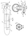
- Figure 3 is a cross-sectional view of the solar thermal aircraft fuselage taken along the line 3-3 of Figure 2 .
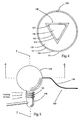
- Figure 4 is an enlarged cross-sectional view of the heat collection element enclosed in the circle 4 of Figure 3a .
- Figure 24 is a cross-sectional view similar to Figure 23 of the embodiment shown in Figure 21 and showing representative sunrays at the winter solstice.
- Figure 26 is an enlarged cross-sectional view of a second of the heat collector of the present invention having a thin-walled heating tube with oblong cross-sectional profile surrounded by an evacuated optically transparent tubular envelope.
- Figure 28 is an enlarged cross-sectional view of a second exemplary embodiment of the heat collector of the present invention having an optically transparent thick-walled heating tube similar to Figure 27 surrounded by an evacuated optically transparent tubular envelope.
- a propulsion device such as a propeller 109 in Figure 1
- an engine such as heat engine 140 to propel the aircraft, and thereby produce lift and sustain free flight of the aircraft.
- Exemplary alternative examples of the aircraft body are shown in Figures 14, 15 and 17 discussed in greater detail below.
- FIGS 1 and 2 also show the solar thermal power plant of the aircraft 100 generally positioned in the interior of the aircraft body, namely the fuselage 103.
- the solar thermal power plant includes a heat engine 140, heat storage means i.e. a thermal battery 130 including a heat storage container and medium, a solar tracking concentrator 110, and a heat collection/transport conduit, device, or other means 120.
- the heat engine 140 is shown mounted in the fuselage 103 at a forward end, with the thermal battery 130 (and in particular the heat storage medium) in thermal contact with a hot side of the heat engine. Due to its internal location, a cooling air inlet channel 108 may be provided to direct ambient air backwash from the propeller 109 to a cold side of the heat engine for cooling.
- FIG 18 An alternative example shown in Figure 18 comprises a rear mount of a heat engine 140, with ambient air sucked past cooling fins 141 by a rearward mounted ducted fan 150.
- the solar tracking concentrator 110 is movably mounted for actuation in an optically transparent section 112 of the aircraft body, shown in Figure 2 as a section of the fuselage 103.
- the optically transparent section 112 has a fuselage skin which is made of an optically transparent, ultraviolet resistant, lightweight material, such as TEDLAR from DuPont, that allows most of the incident solar energy to be transmitted therethrough and to the solar concentrator 110.
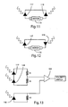
- a preferred method of heliostat operation uses the one center and two outer solar cells in a closed loop feedback stabilization system involving two modes of operation: a sun-searching mode, and a sun-tracking mode, shown in Figures 11-13 .
- the sun-tracking mode the sun is already aligned with the symmetric plane of the reflective parabolic trough, and deviations from alignment are detected.
- both outer cells 117,119 of the heliostat 116 are equally illuminated, while the central cell 118 is in the shadow of the back-reflector 113 of the heat collector 120 (or the shadow of the heat collector itself if a back-reflector is not used).
- the thermal battery 130 includes (1) a heat storage container comprising layers 131,132,133 and (2) a heat storage medium, i.e. thermal battery core 136 contained in the heat storage container.
- the heat storage container i.e. thermal battery container
- it includes several layers of thin, highly reflective material 132, separated by spacers 135, and a highly reflective outer vacuum vessel 131, surround a containment shell structure 133.
- the containment shell structure 133 is further comprised of a primary containment shell 137 and a gold layer 139, described in detail below.
- the layers of highly reflective material act as radiation shields, and provide thermal insulation of the hot thermal battery core 136.
- the cold side of the heat engine can be held relatively cool, and the resulting Carnot heat engine efficiency may exceed 70%. Achieving such efficiency is aided by the design of the air cooling channel 108 shown in Figure 2 .
- the cool air forced past the cooling fins 141 may be driven by the airflow past the aircraft, a forward propeller 109 or a rearward ducted fan 150.
- the full length of the hot side heat exchanger 142 lies within the thermal battery core, while the full span of the regenerator 143 extends across the gap between the thermal battery core and the outer vacuum vessel wall, and the cold side heat exchanger 144 lies within the range of the cooling fins 141. This arrangement maximizes the thermal contact to both the hot and cold thermal reservoirs, and produces a nearly linear temperature gradient across the regenerator.
- the main components of the residential solar thermal power plant are preferably mounted on a fixed structure that is sufficiently exposed to the sun, such as for example a residential rooftop shown in Figure 21 .
- the reject heat from the heat-powered engine is preferably further exploited for its heating value rather than simply dumped to the environment.
- the thermal energy collected by the residential solar thermal power plant may be used in various ways for domestic or commercial consumption, such as for use directly to offset domestic heating requirements, for conversion into mechanical energy for pumping water via the heat engine, or for further conversion into electrical energy with an electric generator.
- the roof-top area per kW of capacity devoted to the solar collector is less than a third the corresponding land area per kW needed in large centralized parabolic trough solar thermal power plants.
- the lowest axial position, throughout the course of a year, struck by concentrated sunlight is represented by point 229G in Figure 23 , and is reached at noon on the summer solstice.
- the highest axial position, reached at noon on the winter solstice is point 229H in Figure 24 .
- the active length of collector assembly 220 that is ever exposed to concentrated sunlight over the course of the year extends only from point 229G to point 229H.
- the maximum degree of foreshortening in the polar aligned case is only attained on the solstices and is only 91.7% in the extreme.
- the primary component of the heat collector 220 shown in Figure 21 is the heating tube 226 shown as a cross-section in Figure 22 coaxially positioned along the focal axis of the parabolic trough concentrating mirror 210.
- the heating tube 226 is shown centered between opposing edges of the parabolic profile of mirror 210 at the focus of the preferably f/0.25 mirror.
- the heating tube is positioned at the focus (i.e. focal axis) of the mirror, whatever its focal length.
- the heat collector 220 and the heating tube 226 are similar to the heat collector 120 and heat pipe 129, respectively, previously discussed with respect to the solar thermal aircraft.
- the major or long axis of this profile is preferably located within the longitudinal symmetry plane 213 (shown in Figure 25 and in Figure 30 ) of concentrator mirror 210, and must thus rotate along with the mirror to follow the sun.
- a channel 228 In the interior of tube 226 is a channel 228 for the passage and transport of a heat transfer fluid, i.e. working fluid.
- the length-to-width ratio for the oblong cross-section of tube 226 (where the length is measured along the major axis, and the width is measured along the minor axis) is preferably two to one.
- such a profile allows the interception of all focused sunlight from mirror 210 with a substantially reduced (compared to a circle) surface area for tube 226, assuming that mirror 210 has a perfect parabolic figure.
- the surface area corresponding to such an oblong tube fashioned of two facing parabolic segments is only 73% that of a circular tube having the same diameter as the major axis of the oblong tube.
- the hydraulic diameter i.e. four times the central channel flow area divided by the perimeter of the central channel
- This decreased hydraulic diameter is helpful for heat transfer purposes.
- FIG. 26 shows an example of a collector assembly 220A having a tube-shaped, circular profile, transparent glass envelope 222A that is preferably radially spaced from and arranged coaxial to tube 226, with a vacuum 224 maintained within transparent glass envelope 222A to eliminate convective cooling of tube 226.
- heat collector assembly 220A is considered the combination of tube 226, glass envelope 222A, and vacuum insulation 224 therebetween.
- vacuum tube construction is well known in the art for parabolic trough solar collectors. With thin walled glass envelopes, there is essentially no degradation of the benefit of the lemon shaped collector itself.
- the glass vacuum envelope may be employed especially in applications where natural convection is expected to produce a greater loss of power than 5%, such as for example with very high temperature operation as is necessary for the aircraft example.
- the glass vacuum envelope may be used, for example, where the collector tube is not used directly for heat recovery, such as previously described where a portion of residential heating is provided by passing air through the windshield interior. It is appreciated that in portions of the system for which concentrated sunlight illumination is not present, such as the section between the collector mirror and the thermal storage shown in Figure 21 , while it may be advantageous to have a vacuum containing envelope surrounding heating tube 226, it is not necessary that it be transparent.
- Figure 27 shows an exemplary heat collector embodiment 220B having an optically transparent thick-walled heating tube 223 having a convex curvilinear outer surface and an inner surface forming a flow channel, with a sunlight absorbing material (e.g. black coating 227) coating the inner surface.
- the outer surface functions as an immersion lens for magnifying the dimensions of the inner surface and the flow channel.
- the thickness of the tube wall preferably has a ratio of an outer surface diameter to the largest inner surface diameter (e.g. length of the major axis of the oblong cross-sectional tube 226) preferably being at least three to one.
- FIG. 27 An example of the effect of this lens action on the converging sunlight is illustrated in Figure 27 , drawn to the same scale as Figure 26 , for rays 229A and 229B.
- rays 229A and 229B As these incoming rays encounter the surface of the thick glass, they bend by refraction, and the solar flux becomes more highly concentrated as it is absorbed at surface 227.
- Such immersion lens action is well known, as in the context of oil immersion microscopy, for example. Since the collector tube appears optically to be larger, it is possible to achieve a higher concentration of the incident sunlight than is ordinarily thought to be feasible with parabolic trough solar collectors.
- Figure 28 shows another exemplary embodiment which modifies the immersion lens 220B of Figure 27 by providing a radially-spaced thin-walled glass vacuum envelope 222C to surround the thick glass envelope with a vacuum region 224 between them to provide even greater thermal insulation.
Landscapes
- Engineering & Computer Science (AREA)
- Physics & Mathematics (AREA)
- Life Sciences & Earth Sciences (AREA)
- Sustainable Development (AREA)
- Sustainable Energy (AREA)
- Thermal Sciences (AREA)
- Chemical & Material Sciences (AREA)
- Combustion & Propulsion (AREA)
- Mechanical Engineering (AREA)
- General Engineering & Computer Science (AREA)
- Photovoltaic Devices (AREA)
- Engine Equipment That Uses Special Cycles (AREA)
Claims (13)
- Sonnenenergiekraftwerk, das folgendes umfasst:einen Parabolrinnenspiegel (210) mit einer longitudinalen Brennachse zur Konzentration von Sonnenlicht entlang dieser;eine Einrichtung (215) zur Anbringung des genannten Spiegels, so dass die Brennachse parallel zu der Erdumdrehungsachse ist, und wobei der genannte Spiegel um eine Längsrotationsachse des Spiegels drehbar ist;eine Einrichtung (215) zum Drehen des genannten Spiegels um eine Längsrotationsachse, so dass der Spiegel der Sonne folgt; undeinen röhrenförmigen Wärmekollektor (220B), der eine Heizröhre (223) umfasst, die koaxial entlang der Brennachse positioniert ist, so dass ein Nutzfluid in einem Durchflusskanal dadurch erhitzt wird, und vorgesehen für einen Einsatz durch ein Auslassende der Heizröhre (223), dadurch gekennzeichnet, dass es sich bei der Heizröhre (223) um eine optisch transparente, dickwandige Heizröhre (223) handelt, mit einer Innenwandoberfläche, die einen Durchflusskanal bildet, und mit einer konvexen, krummlinigen Außenwandoberfläche zur Vergrößerung der Dimensionen des Durchflusskanals, wobei der genannte Durchflusskanal eine längliche Querschnittsform aufweist, gekennzeichnet durch Haupt- und Nebenachsen mit einem größten Durchmesser des Kanals entlang der Hauptachse und mit einem kleinsten Durchmesser des Kanals entlang der Nebenachse, und wobei die Hauptachse mit einer longitudinalen Symmetrieebene (213) des Parabolrinnenspiegels (210) ausgerichtet ist, wobei die genannte Innenwandoberfläche (227) mit einem Sonnenlicht absorbierenden Material überzogen ist.
- Sonnenenergiekraftwerk nach Anspruch 1, wobei das Verhältnis des größten Durchmessers zu dem kleinsten Durchmesser etwa 2:1 beträgt.
- Sonnenenergiekraftwerk nach Anspruch 1, wobei die längliche Querschnittsform des Durchflusskanals durch zwei parabolische Oberflächen gebildet wird, die entlang der Hauptachse verbunden sind, so dass zwei entgegengesetzte Scheitelpunkte gebildet werden.
- Sonnenenergiekraftwerk nach Anspruch 3, wobei jeder der entgegengesetzten Scheitelpunkte einen Winkel von etwa 90 Grad bildet.
- Sonnenenergiekraftwerk nach Anspruch 1, wobei die längliche Querschnittsform des Durchflusskanals vier Seiten mit zwei entgegengesetzten Scheitelpunkten entlang der Hauptachse und zwei entgegengesetzten Scheitelpunkten entlang der Nebenachse aufweist.
- Sonnenenergiekraftwerk nach Anspruch 1, wobei die Einrichtung (215) zur Anbringung des Spiegels den genannten Spiegel (210) so anbringen kann, dass dessen Brennachse gleichzeitig die Rotationsachse ist.
- Sonnenenergiekraftwerk nach Anspruch 1, wobei dieses ferner einen Wärmespeicherbehälter (230) umfasst, der funktionsfähig mit dem Auslassende der Heizröhre (220B) verbunden ist, um speichernd Wärmeenergie zu empfangen, die durch das erhitzte Nutzfluid zu dem Behälter (230) übertragen wird.
- Sonnenenergiekraftwerk nach Anspruch 7, wobei der genannte Wärmespeicherbehälter (230) ferner funktionsfähig mit einem Einlassende der Heizröhre (220B) verbunden ist, um das Nutzfluid in einem geschlossenen Wärmespeicherkreislauf zu dieser zurückzuführen.
- Sonnenenergiekraftwerk nach Anspruch7, wobei der genannte Wärmespeicherbehälter (230) eine Fluidverbindung mit dem Auslassende der Heizröhre (220B) aufweist, um das erhitzte Nutzfluid speichernd davon aufzunehmen.
- Sonnenenergiekraftwerk nach Anspruch 9, wobei der genannte Wärmespeicherbehälter (230) ferner eine Fluidverbindung mit einem Einlassende der Heizröhre (220B) aufweist, um das Nutzfluid in einem geschlossenen Wärmespeicherkreislauf zu dieser zurückzuführen.
- Sonnenenergiekraftwerk nach Anspruch 7, wobei der genannte Wärmespeicherbehälter (230) Wasser und Stein zur Verwendung als Wärmeenergiespeichermedium enthält.
- Sonnenenergiekraftwerk nach Anspruch 1, wobei das Auslassende der Heizröhre (220B) eine Fluidverbindung mit einem Wasserspeicherbehälter (260) aufweist, und wobei die Heizröhre (220B) ein Einlassende aufweist, das mit einer Wasserquelle in fluidübertragungsfähig verbunden werden kann.
- Sonnenenergiekraftwerk nach Anspruch 12, wobei dieses ferner eine Wasserpumpe (235, 236) zum Pumpen von Wasser von der Wasserquelle in das Einlassende und von erhitztem Wasser von dem Auslassende in den Wasserspeicherbehälter umfasst.
Applications Claiming Priority (2)
| Application Number | Priority Date | Filing Date | Title |
|---|---|---|---|
| US11/543,659 US20100326424A1 (en) | 2004-04-30 | 2006-10-04 | Residential solar thermal power plant |
| PCT/US2007/020902 WO2009041947A1 (en) | 2007-09-28 | 2007-09-28 | Residential solar thermal power plant |
Publications (2)
| Publication Number | Publication Date |
|---|---|
| EP2195583A1 EP2195583A1 (de) | 2010-06-16 |
| EP2195583B1 true EP2195583B1 (de) | 2013-03-13 |
Family
ID=42167705
Family Applications (1)
| Application Number | Title | Priority Date | Filing Date |
|---|---|---|---|
| EP07872999A Not-in-force EP2195583B1 (de) | 2006-10-04 | 2007-09-28 | Sonnenwärmekraftanlage für wohnhäuser |
Country Status (3)
| Country | Link |
|---|---|
| EP (1) | EP2195583B1 (de) |
| AU (1) | AU2007359536B2 (de) |
| BR (1) | BRPI0719235A2 (de) |
Families Citing this family (14)
| Publication number | Priority date | Publication date | Assignee | Title |
|---|---|---|---|---|
| EP2757331A1 (de) * | 2013-01-17 | 2014-07-23 | Siemens Concentrated Solar Power Ltd. | Wärmeempfängerrohr mit interner Sonnenlichtreflektoreinheit, Solarkollektor mit Wärmeempfängerrohr und Verwendung des Sonnenkollektors |
| WO2016172647A1 (en) | 2015-04-22 | 2016-10-27 | Sercel Joel C | Optics and structure for space applications |
| CN209027121U (zh) * | 2018-06-22 | 2019-06-25 | 国网冀北节能服务有限公司 | 一种高效太阳能集热联合电能供热系统 |
| US11143026B2 (en) | 2018-08-07 | 2021-10-12 | Trans Astronautica Corporation | Systems and methods for radiant gas dynamic mining of permafrost for propellant extraction |
| US10989443B1 (en) | 2020-01-16 | 2021-04-27 | Trans Astronautica Corporation | Systems and methods for obtaining energy in shadowed regions |
| US11391246B2 (en) | 2020-04-27 | 2022-07-19 | Trans Astronautica Corporation | Omnivorous solar thermal thruster, cooling systems, and thermal energy transfer in rockets |
| US11608196B2 (en) | 2020-07-22 | 2023-03-21 | Trans Astronautica Corporation | Directing light for thermal and power applications in space |
| US12297792B2 (en) | 2020-07-22 | 2025-05-13 | Trans Astronautica Corporation | Hybrid solar thermal and chemical vehicle configurations for space mining applications |
| US11566521B2 (en) | 2020-09-22 | 2023-01-31 | Trans Astronautica Corporation | Systems and methods for radiant gas dynamic mining of permafrost |
| US11598581B2 (en) | 2021-02-12 | 2023-03-07 | Trans Astronautica Corporation | Fabrication of ceramics from celestial materials using microwave sintering and mechanical compression |
| US11702857B2 (en) | 2021-02-26 | 2023-07-18 | Trans Astronautica Corporation | Pneumatically supported towers for low gravity applications |
| US12298042B2 (en) | 2021-09-03 | 2025-05-13 | Trans Astronautica Corporation | Systems and methods for manufacturing in space environments |
| US11748897B1 (en) | 2022-06-24 | 2023-09-05 | Trans Astronautica Corporation | Optimized matched filter tracking of space objects |
| CN116659096B (zh) * | 2023-06-07 | 2025-09-12 | 东北石油大学 | 一种高效的追光型两端冷凝抛物式太阳能热管集热器 |
Family Cites Families (3)
| Publication number | Priority date | Publication date | Assignee | Title |
|---|---|---|---|---|
| US4099514A (en) * | 1974-01-07 | 1978-07-11 | Mario Posnansky | Method and apparatus for heating a fluid medium by means of solar energy |
| US4475537A (en) * | 1981-11-24 | 1984-10-09 | Advanced Solar Systems | Nontracking parabolic collector apparatus |
| US4469938A (en) * | 1983-08-18 | 1984-09-04 | Cohen Elie | Solar tracking unit |
-
2007
- 2007-09-28 EP EP07872999A patent/EP2195583B1/de not_active Not-in-force
- 2007-09-28 BR BRPI0719235-5A patent/BRPI0719235A2/pt not_active IP Right Cessation
- 2007-09-28 AU AU2007359536A patent/AU2007359536B2/en not_active Ceased
Also Published As
| Publication number | Publication date |
|---|---|
| EP2195583A1 (de) | 2010-06-16 |
| AU2007359536A1 (en) | 2009-04-02 |
| AU2007359536B2 (en) | 2012-05-03 |
| BRPI0719235A2 (pt) | 2014-01-28 |
Similar Documents
| Publication | Publication Date | Title |
|---|---|---|
| EP2195583B1 (de) | Sonnenwärmekraftanlage für wohnhäuser | |
| US7270295B2 (en) | Solar thermal aircraft | |
| US7637457B2 (en) | Rankine-Brayton engine powered solar thermal aircraft | |
| US20100326424A1 (en) | Residential solar thermal power plant | |
| Tyagi et al. | Advancement in solar photovoltaic/thermal (PV/T) hybrid collector technology | |
| US9476612B2 (en) | Beam-forming concentrating solar thermal array power systems | |
| US8413442B2 (en) | System for sustaining and storing green solar energy | |
| US20080236569A1 (en) | System and Method for Concentrating Sunlight | |
| CA2664827C (en) | Residential solar thermal power plant | |
| EP0025305B1 (de) | Absorber für elektromagnetische Energie | |
| US10566926B2 (en) | Systems and methods for collecting solar energy using a parabolic trough solar collector | |
| US10476426B2 (en) | Systems and methods for collecting solar energy using a tilted linear solar collector | |
| Singh et al. | A review on solar energy collection for thermal applications | |
| CN101529168A (zh) | 住宅太阳热能设备 | |
| RU2730188C1 (ru) | Солнечная электростанция | |
| US11828495B1 (en) | Solar energy collector and power generation system | |
| Sukhatme | Solar thermal power generation | |
| Yellott | Power from solar energy | |
| Bennett | Solar thermal aircraft | |
| Loumakis | Sustainable solar energy | |
| Arya et al. | Molten Salt Thermal Storage Systems for Solar Energy Concentrators | |
| Somalwal | A Review of Solar Collectors in Solar Thermal Applications | |
| Peters | Comparative technical evaluation of solar collectors | |
| Vardhan et al. | A REVIEW ON SOLAR ENERGY COLLECTION FOR THERMAL APPLICATIONS | |
| Tabor | Thermal Conversion of Solar Energy |
Legal Events
| Date | Code | Title | Description |
|---|---|---|---|
| PUAI | Public reference made under article 153(3) epc to a published international application that has entered the european phase |
Free format text: ORIGINAL CODE: 0009012 |
|
| 17P | Request for examination filed |
Effective date: 20090430 |
|
| AK | Designated contracting states |
Kind code of ref document: A1 Designated state(s): AT BE BG CH CY CZ DE DK EE ES FI FR GB GR HU IE IS IT LI LT LU LV MC MT NL PL PT RO SE SI SK TR |
|
| REG | Reference to a national code |
Ref country code: HK Ref legal event code: DE Ref document number: 1144009 Country of ref document: HK |
|
| GRAP | Despatch of communication of intention to grant a patent |
Free format text: ORIGINAL CODE: EPIDOSNIGR1 |
|
| RAP1 | Party data changed (applicant data changed or rights of an application transferred) |
Owner name: LAWRENCE LIVERMORE NATIONAL SECURITY, LLC |
|
| RAP1 | Party data changed (applicant data changed or rights of an application transferred) |
Owner name: LAWRENCE LIVERMORE NATIONAL SECURITY, LLC |
|
| GRAS | Grant fee paid |
Free format text: ORIGINAL CODE: EPIDOSNIGR3 |
|
| GRAP | Despatch of communication of intention to grant a patent |
Free format text: ORIGINAL CODE: EPIDOSNIGR1 |
|
| GRAA | (expected) grant |
Free format text: ORIGINAL CODE: 0009210 |
|
| AK | Designated contracting states |
Kind code of ref document: B1 Designated state(s): AT BE BG CH CY CZ DE DK EE ES FI FR GB GR HU IE IS IT LI LT LU LV MC MT NL PL PT RO SE SI SK TR |
|
| REG | Reference to a national code |
Ref country code: GB Ref legal event code: FG4D |
|
| REG | Reference to a national code |
Ref country code: AT Ref legal event code: REF Ref document number: 601035 Country of ref document: AT Kind code of ref document: T Effective date: 20130315 Ref country code: CH Ref legal event code: EP |
|
| REG | Reference to a national code |
Ref country code: IE Ref legal event code: FG4D |
|
| REG | Reference to a national code |
Ref country code: DE Ref legal event code: R096 Ref document number: 602007029137 Country of ref document: DE Effective date: 20130508 |
|
| PG25 | Lapsed in a contracting state [announced via postgrant information from national office to epo] |
Ref country code: SE Free format text: LAPSE BECAUSE OF FAILURE TO SUBMIT A TRANSLATION OF THE DESCRIPTION OR TO PAY THE FEE WITHIN THE PRESCRIBED TIME-LIMIT Effective date: 20130313 Ref country code: ES Free format text: LAPSE BECAUSE OF FAILURE TO SUBMIT A TRANSLATION OF THE DESCRIPTION OR TO PAY THE FEE WITHIN THE PRESCRIBED TIME-LIMIT Effective date: 20130624 Ref country code: BG Free format text: LAPSE BECAUSE OF FAILURE TO SUBMIT A TRANSLATION OF THE DESCRIPTION OR TO PAY THE FEE WITHIN THE PRESCRIBED TIME-LIMIT Effective date: 20130613 Ref country code: LT Free format text: LAPSE BECAUSE OF FAILURE TO SUBMIT A TRANSLATION OF THE DESCRIPTION OR TO PAY THE FEE WITHIN THE PRESCRIBED TIME-LIMIT Effective date: 20130313 |
|
| REG | Reference to a national code |
Ref country code: AT Ref legal event code: MK05 Ref document number: 601035 Country of ref document: AT Kind code of ref document: T Effective date: 20130313 |
|
| REG | Reference to a national code |
Ref country code: NL Ref legal event code: VDEP Effective date: 20130313 |
|
| REG | Reference to a national code |
Ref country code: LT Ref legal event code: MG4D |
|
| PG25 | Lapsed in a contracting state [announced via postgrant information from national office to epo] |
Ref country code: GR Free format text: LAPSE BECAUSE OF FAILURE TO SUBMIT A TRANSLATION OF THE DESCRIPTION OR TO PAY THE FEE WITHIN THE PRESCRIBED TIME-LIMIT Effective date: 20130614 Ref country code: SI Free format text: LAPSE BECAUSE OF FAILURE TO SUBMIT A TRANSLATION OF THE DESCRIPTION OR TO PAY THE FEE WITHIN THE PRESCRIBED TIME-LIMIT Effective date: 20130313 Ref country code: FI Free format text: LAPSE BECAUSE OF FAILURE TO SUBMIT A TRANSLATION OF THE DESCRIPTION OR TO PAY THE FEE WITHIN THE PRESCRIBED TIME-LIMIT Effective date: 20130313 Ref country code: LV Free format text: LAPSE BECAUSE OF FAILURE TO SUBMIT A TRANSLATION OF THE DESCRIPTION OR TO PAY THE FEE WITHIN THE PRESCRIBED TIME-LIMIT Effective date: 20130313 |
|
| PG25 | Lapsed in a contracting state [announced via postgrant information from national office to epo] |
Ref country code: BE Free format text: LAPSE BECAUSE OF FAILURE TO SUBMIT A TRANSLATION OF THE DESCRIPTION OR TO PAY THE FEE WITHIN THE PRESCRIBED TIME-LIMIT Effective date: 20130313 |
|
| PG25 | Lapsed in a contracting state [announced via postgrant information from national office to epo] |
Ref country code: IS Free format text: LAPSE BECAUSE OF FAILURE TO SUBMIT A TRANSLATION OF THE DESCRIPTION OR TO PAY THE FEE WITHIN THE PRESCRIBED TIME-LIMIT Effective date: 20130713 Ref country code: RO Free format text: LAPSE BECAUSE OF FAILURE TO SUBMIT A TRANSLATION OF THE DESCRIPTION OR TO PAY THE FEE WITHIN THE PRESCRIBED TIME-LIMIT Effective date: 20130313 Ref country code: PT Free format text: LAPSE BECAUSE OF FAILURE TO SUBMIT A TRANSLATION OF THE DESCRIPTION OR TO PAY THE FEE WITHIN THE PRESCRIBED TIME-LIMIT Effective date: 20130715 Ref country code: CZ Free format text: LAPSE BECAUSE OF FAILURE TO SUBMIT A TRANSLATION OF THE DESCRIPTION OR TO PAY THE FEE WITHIN THE PRESCRIBED TIME-LIMIT Effective date: 20130313 Ref country code: AT Free format text: LAPSE BECAUSE OF FAILURE TO SUBMIT A TRANSLATION OF THE DESCRIPTION OR TO PAY THE FEE WITHIN THE PRESCRIBED TIME-LIMIT Effective date: 20130313 Ref country code: NL Free format text: LAPSE BECAUSE OF FAILURE TO SUBMIT A TRANSLATION OF THE DESCRIPTION OR TO PAY THE FEE WITHIN THE PRESCRIBED TIME-LIMIT Effective date: 20130313 Ref country code: EE Free format text: LAPSE BECAUSE OF FAILURE TO SUBMIT A TRANSLATION OF THE DESCRIPTION OR TO PAY THE FEE WITHIN THE PRESCRIBED TIME-LIMIT Effective date: 20130313 Ref country code: SK Free format text: LAPSE BECAUSE OF FAILURE TO SUBMIT A TRANSLATION OF THE DESCRIPTION OR TO PAY THE FEE WITHIN THE PRESCRIBED TIME-LIMIT Effective date: 20130313 |
|
| PG25 | Lapsed in a contracting state [announced via postgrant information from national office to epo] |
Ref country code: PL Free format text: LAPSE BECAUSE OF FAILURE TO SUBMIT A TRANSLATION OF THE DESCRIPTION OR TO PAY THE FEE WITHIN THE PRESCRIBED TIME-LIMIT Effective date: 20130313 Ref country code: CY Free format text: LAPSE BECAUSE OF FAILURE TO SUBMIT A TRANSLATION OF THE DESCRIPTION OR TO PAY THE FEE WITHIN THE PRESCRIBED TIME-LIMIT Effective date: 20130313 |
|
| PLBE | No opposition filed within time limit |
Free format text: ORIGINAL CODE: 0009261 |
|
| STAA | Information on the status of an ep patent application or granted ep patent |
Free format text: STATUS: NO OPPOSITION FILED WITHIN TIME LIMIT |
|
| PG25 | Lapsed in a contracting state [announced via postgrant information from national office to epo] |
Ref country code: DK Free format text: LAPSE BECAUSE OF FAILURE TO SUBMIT A TRANSLATION OF THE DESCRIPTION OR TO PAY THE FEE WITHIN THE PRESCRIBED TIME-LIMIT Effective date: 20130313 |
|
| 26N | No opposition filed |
Effective date: 20131216 |
|
| PG25 | Lapsed in a contracting state [announced via postgrant information from national office to epo] |
Ref country code: IT Free format text: LAPSE BECAUSE OF FAILURE TO SUBMIT A TRANSLATION OF THE DESCRIPTION OR TO PAY THE FEE WITHIN THE PRESCRIBED TIME-LIMIT Effective date: 20130313 |
|
| REG | Reference to a national code |
Ref country code: DE Ref legal event code: R097 Ref document number: 602007029137 Country of ref document: DE Effective date: 20131216 |
|
| PG25 | Lapsed in a contracting state [announced via postgrant information from national office to epo] |
Ref country code: MC Free format text: LAPSE BECAUSE OF FAILURE TO SUBMIT A TRANSLATION OF THE DESCRIPTION OR TO PAY THE FEE WITHIN THE PRESCRIBED TIME-LIMIT Effective date: 20130313 |
|
| REG | Reference to a national code |
Ref country code: CH Ref legal event code: PL |
|
| GBPC | Gb: european patent ceased through non-payment of renewal fee |
Effective date: 20130928 |
|
| REG | Reference to a national code |
Ref country code: IE Ref legal event code: MM4A |
|
| PG25 | Lapsed in a contracting state [announced via postgrant information from national office to epo] |
Ref country code: LI Free format text: LAPSE BECAUSE OF NON-PAYMENT OF DUE FEES Effective date: 20130930 Ref country code: GB Free format text: LAPSE BECAUSE OF NON-PAYMENT OF DUE FEES Effective date: 20130928 Ref country code: IE Free format text: LAPSE BECAUSE OF NON-PAYMENT OF DUE FEES Effective date: 20130928 Ref country code: CH Free format text: LAPSE BECAUSE OF NON-PAYMENT OF DUE FEES Effective date: 20130930 |
|
| PGFP | Annual fee paid to national office [announced via postgrant information from national office to epo] |
Ref country code: FR Payment date: 20140917 Year of fee payment: 8 |
|
| PGFP | Annual fee paid to national office [announced via postgrant information from national office to epo] |
Ref country code: DE Payment date: 20140929 Year of fee payment: 8 |
|
| PG25 | Lapsed in a contracting state [announced via postgrant information from national office to epo] |
Ref country code: TR Free format text: LAPSE BECAUSE OF FAILURE TO SUBMIT A TRANSLATION OF THE DESCRIPTION OR TO PAY THE FEE WITHIN THE PRESCRIBED TIME-LIMIT Effective date: 20130313 Ref country code: MT Free format text: LAPSE BECAUSE OF FAILURE TO SUBMIT A TRANSLATION OF THE DESCRIPTION OR TO PAY THE FEE WITHIN THE PRESCRIBED TIME-LIMIT Effective date: 20130313 |
|
| PG25 | Lapsed in a contracting state [announced via postgrant information from national office to epo] |
Ref country code: HU Free format text: LAPSE BECAUSE OF FAILURE TO SUBMIT A TRANSLATION OF THE DESCRIPTION OR TO PAY THE FEE WITHIN THE PRESCRIBED TIME-LIMIT; INVALID AB INITIO Effective date: 20070928 Ref country code: LU Free format text: LAPSE BECAUSE OF NON-PAYMENT OF DUE FEES Effective date: 20130928 |
|
| REG | Reference to a national code |
Ref country code: DE Ref legal event code: R119 Ref document number: 602007029137 Country of ref document: DE |
|
| REG | Reference to a national code |
Ref country code: FR Ref legal event code: ST Effective date: 20160531 |
|
| PG25 | Lapsed in a contracting state [announced via postgrant information from national office to epo] |
Ref country code: DE Free format text: LAPSE BECAUSE OF NON-PAYMENT OF DUE FEES Effective date: 20160401 |
|
| PG25 | Lapsed in a contracting state [announced via postgrant information from national office to epo] |
Ref country code: FR Free format text: LAPSE BECAUSE OF NON-PAYMENT OF DUE FEES Effective date: 20150930 |
|
| REG | Reference to a national code |
Ref country code: HK Ref legal event code: WD Ref document number: 1144009 Country of ref document: HK |