EP2195908B1 - Elektrische maschine und rotoranordnung - Google Patents
Elektrische maschine und rotoranordnung Download PDFInfo
- Publication number
- EP2195908B1 EP2195908B1 EP08787348.5A EP08787348A EP2195908B1 EP 2195908 B1 EP2195908 B1 EP 2195908B1 EP 08787348 A EP08787348 A EP 08787348A EP 2195908 B1 EP2195908 B1 EP 2195908B1
- Authority
- EP
- European Patent Office
- Prior art keywords
- rotor
- permanent magnet
- pole
- contour
- arrangement
- Prior art date
- Legal status (The legal status is an assumption and is not a legal conclusion. Google has not performed a legal analysis and makes no representation as to the accuracy of the status listed.)
- Revoked
Links
- 230000004907 flux Effects 0.000 claims description 52
- 230000004888 barrier function Effects 0.000 claims description 28
- 230000001360 synchronised effect Effects 0.000 claims description 7
- 230000010287 polarization Effects 0.000 claims 1
- 238000004519 manufacturing process Methods 0.000 description 3
- 238000003780 insertion Methods 0.000 description 2
- 230000037431 insertion Effects 0.000 description 2
- 230000001419 dependent effect Effects 0.000 description 1
- 238000010586 diagram Methods 0.000 description 1
- 238000011835 investigation Methods 0.000 description 1
- 238000007493 shaping process Methods 0.000 description 1
Images


Classifications
-
- H—ELECTRICITY
- H02—GENERATION; CONVERSION OR DISTRIBUTION OF ELECTRIC POWER
- H02K—DYNAMO-ELECTRIC MACHINES
- H02K1/00—Details of the magnetic circuit
- H02K1/06—Details of the magnetic circuit characterised by the shape, form or construction
- H02K1/22—Rotating parts of the magnetic circuit
- H02K1/27—Rotor cores with permanent magnets
- H02K1/2706—Inner rotors
- H02K1/272—Inner rotors the magnetisation axis of the magnets being perpendicular to the rotor axis
- H02K1/274—Inner rotors the magnetisation axis of the magnets being perpendicular to the rotor axis the rotor consisting of two or more circumferentially positioned magnets
- H02K1/2753—Inner rotors the magnetisation axis of the magnets being perpendicular to the rotor axis the rotor consisting of two or more circumferentially positioned magnets the rotor consisting of magnets or groups of magnets arranged with alternating polarity
- H02K1/276—Magnets embedded in the magnetic core, e.g. interior permanent magnets [IPM]
-
- H—ELECTRICITY
- H02—GENERATION; CONVERSION OR DISTRIBUTION OF ELECTRIC POWER
- H02K—DYNAMO-ELECTRIC MACHINES
- H02K1/00—Details of the magnetic circuit
- H02K1/06—Details of the magnetic circuit characterised by the shape, form or construction
- H02K1/22—Rotating parts of the magnetic circuit
- H02K1/27—Rotor cores with permanent magnets
- H02K1/2706—Inner rotors
- H02K1/272—Inner rotors the magnetisation axis of the magnets being perpendicular to the rotor axis
- H02K1/274—Inner rotors the magnetisation axis of the magnets being perpendicular to the rotor axis the rotor consisting of two or more circumferentially positioned magnets
- H02K1/2746—Inner rotors the magnetisation axis of the magnets being perpendicular to the rotor axis the rotor consisting of two or more circumferentially positioned magnets the rotor consisting of magnets arranged with the same polarity, e.g. consequent pole type
-
- H—ELECTRICITY
- H02—GENERATION; CONVERSION OR DISTRIBUTION OF ELECTRIC POWER
- H02K—DYNAMO-ELECTRIC MACHINES
- H02K2213/00—Specific aspects, not otherwise provided for and not covered by codes H02K2201/00 - H02K2211/00
- H02K2213/03—Machines characterised by numerical values, ranges, mathematical expressions or similar information
Definitions
- the invention relates to a rotor assembly for an electric machine, in particular for a brushless permanent magnet excited synchronous machine with buried permanent magnets and in particular a rotor assembly in which the cogging torque and the torque ripple is reduced.
- the rotor pole pieces of the rotor are provided with a certain shape.
- the shaping of the rotor pole shoes takes place in such a way that the most sinusoidal air gap flux density distribution results.
- the outer edge of the pole piece is provided for this purpose with a contour through which an air gap is formed between two adjacent rotor pole pieces and which, proceeding from the center of the rotor pole piece, essentially follows an inverse cosine function.
- a shaped contour of a rotor pole piece is called a Richter contour ( Richter, R., Electrical Machines, Vol. I, General Calculation Elements, The DC Machine, 3rd ed., Birk Reifen-Verlag, Basel 1967, pages 168-170 ) designated.
- the Richter contour produces an air gap flux density distribution with a distortion factor of typically less than 2% and thus an almost ideal sinusoidal air gap flux density distribution.
- the manufacture of a rotor with a Richter contour is complicated in design and manufacture and it is used for simplicity therefore an arc contour for the outer contour of the rotor pole pieces.
- the arc contour is defined by an outer radius of a circle segment, which has a smaller radius than the rotor outer diameter and its center to the shaft of the rotor along the center line of the relevant Rotor pole shoe is offset.
- Such a so-called center offset sheet contour is a simple approach to the Richter contour and produces approximately a sinusoidal air gap flux density distribution with a distortion factor of about 5%.
- the US 2004256940 A1 and the JP 2000197292 show a rotor with buried magnets, the magnets are stored in designated pockets.
- the magnets extend substantially in the tangential direction with respect to the circumference of the rotor.
- the invention relates to an electrical machine, in particular for a permanent magnet excited synchronous machine.
- the electric machine comprises a rotor arrangement with buried permanent magnets, and a stator arrangement with an inner recess for rotatably receiving the rotor arrangement.
- the rotor assembly comprises a plurality of rotor segments, each having a pole piece whose outer contour corresponds to an arc contour with a contour radius, wherein the contour radius is smaller than the radius of the rotor assembly, so that a gap is formed between two adjacent rotor segments.
- the at least one outer contour of one of the rotor segments has an arc contour which is designed such that an air gap length ratio of the radial distance between the inner recess and the outer contour is optimized along a radial outer boundary of the corresponding rotor segment and the radial distance between the inner recess and the outer contour along a radial center axis of the corresponding rotor segment with respect to the distortion factor of the course of the flux density distribution of the pole piece, wherein in particular the air gap length ratio is selected such that the harmonic distortion is minimized.
- the air gap length ratio may be between 2.6 and 2.9.
- an arc contour is provided as an outer contour of the pole pieces, which is much easier to implement in a rotor assembly, than a more optimal Richter contour.
- a Flußbarr Schlieren Scheme between the permanent magnet and the lateral boundary of the rotor segment may be provided laterally of the permanent magnets to suppress a short circuit of the magnetic flux through the permanent magnet associated rotor segment.
- further Flußbarrieren Schemee between the permanent magnet and the outer contour of the associated pole piece may be provided, which are arranged on the lateral boundaries of the rotor segment facing sides of the permanent magnet to reduce the effective width of the permanent magnet in the tangential direction of the rotor assembly.
- the ratio between the width of the permanent magnet reduced by the further flux barrier regions and that of the overall width of the permanent magnet with respect to the distortion factor of the profile of the flux density distribution of the pole piece can be optimized.
- the ratio between the width of the permanent magnet reduced by the further flux barrier regions and that of the total width of the permanent magnet can be in a range between 0.77 and 0.81, in particular 0.79.
- the rotor arrangement may have a follower pole arrangement, in which only every second rotor segment is provided with permanent magnets, wherein the permanent magnets have a similar polarity with respect to the radial direction, wherein at the two boundaries of one of the follower pole rotor segment arranged between two rotor segments provided with permanent magnets.
- a rotor arrangement in particular for a permanent magnet-excited synchronous machine, is provided.
- the rotor assembly comprises a plurality of rotor segments, each having a pole piece whose outer contour corresponds to an arc contour with a contour radius, wherein the contour radius is smaller than the radius of the rotor assembly, so that between two adjacent rotor segments, a gap is formed; wherein at least one rotor segment has a buried permanent magnet.
- Such a rotor arrangement also makes it possible to optimize the flux density course when using a curved contour as the outer contour of a pole piece.
- Fig. 1 shows a cross-sectional view through an electric machine in particular by a permanent magnet synchronous motor 1 with a stator 2, in which a StatorausNOung 3 is located.
- a rotor assembly 4 is arranged rotatably about a shaft.
- the stator assembly 2 has stator teeth 5 (inwardly facing) in the direction of the rotor assembly 4, all or part of which are wound by stator coils (not shown).
- the stator teeth 5 are widened towards the stator recess 3 and are each provided with a circular segment-shaped contour which defines a major part of the inner surface of the stator recess 3.
- the stator assembly 2 is preferably composed in the axial direction (axial direction of the rotor assembly) of sheets, which are preferably produced by stamping, so that the stator assembly 2 is provided as a laminated core available.
- FIG. 2 a more detailed illustration of the rotor assembly 4 is shown.
- the rotor assembly 4 has permanent magnets 6, which is arranged in the interior of the rotor assembly 4 in pockets 9, and thus are "buried".
- the permanent magnets 6 are each arranged in rotor segments 7, and each have a pole piece 10.
- the polarity of the permanent magnets 6 is in the radial direction.
- each a Flußbarr Schlieren Scheme 8 is provided, which is formed substantially as an air-filled recess in the rotor assembly 4 forming laminated core.
- the flux barrier regions 8 of two adjacent rotor segments 7 are separated from each other by a web in the rotor assembly 4, to fix the radially outwardly located portions of the rotor assembly 4, which constitute the pole pieces 10, to the rotor assembly 4.
- the permanent magnets 6 are provided in the correspondingly formed pockets 9 in the rotor assembly, the pockets having a shape such that after insertion of the permanent magnet 6 the flux barrier regions 8 remain on both sides of the permanent magnet 6 (in the tangential direction).
- conventional pole pieces of a rotor assembly 4 may be formed without a specific contour, so that the outer contour of the rotor assembly is circular.
- a rotor assembly 4 is shown, are provided in the pole pieces 10 with a curved contour in order to achieve a sinusoidal air gap flux density distribution as possible.
- the arc contour is defined as a circle segment of a to the center of the shaft of the rotor assembly 4 along a radial center line (symmetry line) of the corresponding rotor segment 7 offset auxiliary circle having a correspondingly smaller radius than the rotor assembly.
- a rotor segment 7 of the rotor assembly 4 is shown in fragmentary form.
- the rotor segment 7 comprises the pocket 9, in which the permanent magnet 6 is embedded.
- the pocket 9 preferably has a shape, so that after introduction of the permanent magnet 6 laterally of the permanent magnet, ie in substantially tangential direction, the above-mentioned flow barrier regions 8 remain to prevent a magnetic short circuit from occurring through the material of the rotor segment 7.
- the pocket 9 may be formed so that after insertion of the permanent magnet 6 above, ie in the radial direction outward, another Flußbarr Schlieren Scheme 12 remains on the sides of the permanent magnet 6.
- the further flux barrier region 12 extends on both sides from the edge assigned to the adjacent rotor segment 7 along the profile of the radially outer surface of the permanent magnet 6.
- the outer boundary of the further flux barrier region 12 preferably runs substantially parallel to the outer contour of the pole shoe 10.
- the further flux barrier regions 12 define the effective pole piece width p, which is smaller than the magnet width m when providing the further flux barrier regions 12.
- the outer contour 13 of the pole piece 10 is substantially circular segment-shaped and has a smaller radius than the radius of the rotor assembly.
- the entire rotor segment 7 is constructed mirror-symmetrically substantially to a d-axis. Between the Statorausappelung 3 and the outer contour 13 of the rotor segment 7 are due to the different radii of curvature different distances.
- the air gap distance between the inner surface of the Statorausappelung 3 and the outer contour on the d-axis as d and the air gap spacing between the surfaces along the q axis is referred to as q.
- the relationship between the inner radius of the stator recess 3, the radius of the rotor assembly 4, and the outer contour 13 of the pole pieces 10 can be independently defined by the air gap length ratio q / d of the air gap distances from the respective radii.
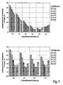
- FIGS. 5a-5e are exemplary embodiments of different air gap length ratios q / d shown different embodiments of rotor segments 7, in which it can be seen that the stronger the curvature of the outer contour of the pole piece, the greater the distance q from the distance d. If one then examines the air gap flux density profile of such a pole shoe with an arc contour depending on the air gap length ratio for the air gap length ratios 1.0, 1.5, 2.0, 2.5, 3.0, 3.5, it can be seen as in FIG Fig. 6 Fig.
- the optimum air gap length ratio is in the range of 2.6 to 2.9, preferably in the range of 2.7 to 2.8, and more preferably in the range of 2.7 to 2.75, more preferably 2.7 ,
- the pole piece magnet width ratio p / m is determined by the width of the further flux barrier regions 12, which covers the radially outwardly directed side of the permanent magnet 6 at its edge regions assigned to the adjacent rotor segments 7. How to get out Fig. 7
- the optimum pole shoe is at different air gap length ratios.
- Magnetic width ratio p / m is in a range between 0.65 and 1, preferably in a range between 0.77 and 0.81 and more preferably at 0.79.
- the width of the further flux barrier regions 12 does not influence or to an extent that can not be determined the optimum value of the air gap length ratio q / d.
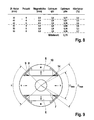
- Fig. 8 is the optimal air gap length ratio q / d and the optimum pole shoe magnet width ratios p / m for different rotor diameters, different number of poles and different magnet heights shown and one recognizes that the optimum air gap length ratio varies only insignificantly in the range between 2.6 and 2.8 and the optimum pole-to-magnet ratio in the range of 0.77 to 0.81.
- a rotor assembly 4 according to another embodiment of the invention is shown.
- the rotor assembly 4 of Fig. 9 is four-pole and has only two permanent magnets 6.
- the permanent magnets 6 are oppositely poled to one another and arranged opposite one another with respect to the shaft of the rotor arrangement 4 and thus form a follower pole arrangement.
- the pockets 9 are formed according to the optimized pole piece magnet width ratio p / m of 0.79, as described above. As a result, an approximately sinusoidal profile of the flux density of the pole shoes 10 provided with the permanent magnets and the follower pole pole shoes is achieved.
- the embodiment of the Fig. 9 is not limited to 4 poles, but a follower pole arrangement with any even number of poles may be provided.
- follower pole flux barrier regions 14 are provided in each rotor segment 7 of one of the follower poles, for example as recesses laterally at the radial boundaries of the rotor segments 7 of the follower poles in order to reduce the effective follower pole width.
- the follower pole flux barrier regions 14 can likewise be part of the pockets 9 for the permanent magnets 6 and are provided in particular as extensions of the flux barrier regions 8 in the direction of a center line of the rotor segment 7 of the follower pole.
- the shape of the follower pole flux barrier regions 14 can be essentially arbitrary, but the follower pole flux barrier regions 14 preferably have an edge limited in the radial direction, which follows the profile of the outer contour of the rotor assembly 4.
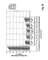
- the relationship between the reduced angle of the follower pole and the total angle of a rotor segment 7 is referred to as the follower pole pole pitch ratio ⁇ f / p .
- Out Fig. 10 The result is an optimum follow-up pole pole-pitch ratio in the range between 0.63 to 0.87, preferably in the range between 0.73 to 0.76 and in particular more preferably 0.73.
Landscapes
- Engineering & Computer Science (AREA)
- Power Engineering (AREA)
- Permanent Field Magnets Of Synchronous Machinery (AREA)
- Iron Core Of Rotating Electric Machines (AREA)
Description
- Die Erfindung betrifft eine Rotoranordnung für eine elektrische Maschine, insbesondere für eine bürstenlose Permanentmagnet erregte Synchronmaschine mit vergrabenen Permanentmagneten und insbesondere eine Rotoranordnung, bei der das Rastmoment und die Drehmomentenwelligkeit reduziert ist.
- Um das Rastmoment und Drehmomentenwelligkeit eines elektrischen Antriebs, z.B. eines bürstenlosen Permanentmagnet erregten Synchronmotors, bei dem der Rotor vergrabene Permanentmagnete aufweist, zu reduzieren, werden die Rotorpolschuhe des Rotors mit einer bestimmten Form versehen. Die Formung der Rotorpolschuhe erfolgt in einer Weise, dass eine möglichst sinusförmige Luftspaltflussdichteverteilung entsteht.
- Bislang wird dazu der äußere Rand des Polschuhs mit einer Kontur versehen, durch die zwischen zwei benachbarten Rotorpolschuhen ein Luftspalt gebildet wird und die ausgehend vom Zentrum des Rotorpolschuhs im wesentlichen entsprechend einer inversen Cosinusfunktion verläuft. Eine derartig geformte Kontur eines Rotorpolschuhs wird als so genannte Richter-Kontur (Richter, R., Elektrische Maschinen, Bd. I, Allgemeine Berechnungselemente, Die Gleichstrommaschine, 3. Aufl., Birkhäuser-Verlag, Basel 1967, Seiten 168-170) bezeichnet.
- Die Richter-Kontur erzeugt eine Luftspaltflussdichtenverteilung mit einem Klirrfaktor von typischerweise weniger als 2% und somit eine fast ideale sinusförmige Luftspaltflussdichteverteilung. Das Herstellen eines Rotors mit einer Richter-Kontur ist aufwendig in Design und Herstellung und man verwendet zur Vereinfachung deshalb auch eine Bogenkontur für die Außenkontur der Rotorpolschuhe. Die Bogenkontur ist definiert durch einen Außenradius eines Kreissegmentes, das einen kleineren Radius aufweist als der Rotoraußendurchmesser und dessen Mittelpunkt zur Welle des Rotors entlang der Mittellinie des betreffenden Rotorpolschuhs versetzt ist. Eine solche so genannte zentrumsversetzte Bogenkontur ist eine einfache Annäherung an die Richter-Kontur und erzeugt annähernd eine sinusförmige Luftspaltflussdichteverteilung mit einem Klirrfaktor von ca. 5%. Dies führt zwar zu einem etwas höheren Rastmoment und einer höheren Drehmomentenwelligkeit als bei einem Rotor mit einer Richter-Kontur, der Entwurf und die Herstellung einer derartigen Rotoranordnung wird jedoch erheblich vereinfacht.
- Der für eine möglichst sinusförmige Luftspaltflussdichteverteilung optimale Bogenradius bei Verwendung der zentrumsversetzten Bogenkontur und sein Versatz aus dem Wellenzentrum ist jedoch nicht bekannt.
- Die
US 2004256940 A1 und dieJP 2000197292 - Es ist daher Aufgabe der vorliegenden Erfindung, eine elektrische Maschine sowie eine Rotoranordnung für eine elektrische Maschine zur Verfügung zu stellen, deren Rotorpolschuhe eine zentrumsversetzte Bogenkontur aufweist, wobei die Rotoranordnung hinsichtlich einer möglichst sinusförmigen Luftspaltflussdichteverteilung optimiert ist.
- Diese Aufgabe wird durch die elektrische Maschine gemäß Anspruch 1 und durch die Rotoranordnung gemäß Anspruch 7 gelöst.
- Weitere vorteilhafte Ausgestaltungen der Erfindung sind in den abhängigen Ansprüchen angegeben.
- Die Erfindung betrifft eine elektrische Maschine, insbesondere für eine Permanentmagnet erregten Synchronmaschine. Die Elektrische Maschine umfasst eine Rotoranordnung mit vergrabenen Permanentmagneten, und eine Statoranordnung mit einer Innenausnehmung zur drehbeweglichen Aufnahme der Rotoranordnung. Die Rotoranordnung umfasst mehrere Rotorsegmente, die jeweils einen Polschuh aufweisen, dessen Außenkontur einer Bogenkontur mit einem Konturradius entspricht, wobei der.Konturradius kleiner ist als der Radius der Rotoranordnung, so dass zwischen zwei benachbarten Rotorsegmenten ein Spalt entsteht. Die mindestens eine Außenkontur eines der Rotorsegmente weist eine Bogenkontur auf, die so gestaltet ist, dass ein Luftspaltlängenverhältnis des radialen Abstandes zwischen der Innenausnehmung und der Außenkontur entlang einer radialen Außenbegrenzung des entsprechenden Rotorsegmentes und des radialen Abstandes zwischen der Innenausnehmung und der Außenkontur entlang einer radialen Mittenachse des entsprechenden Rotorsegmentes hinsichtlich des Klirrfaktors des Verlaufs der Flussdichteverteilung des Polschuhs optimiert ist, wobei insbesondere das Luftspaltlängenverhältnis so gewählt ist, dass der Klirrfaktor minimiert ist. Vorzugsweise kann das Luftspaltlängenverhältnis zwischen 2,6 und 2,9 liegen.
- Bei einer derartigen elektrische Maschine wird eine Bogenkontur als Außenkontur der Polschuhe vorgesehen, die deutlicher einfacher in einer Rotoranordnung zu implementieren ist, als eine optimalere Richter-Kontur. Durch die Optimierung eines Parameters der Bogenkontur ist es möglich den Flussdichteverlauf der Polschuhe an den sinusförmigen Idealverlauf anzunähern.
- Weiterhin kann seitlich der Permanentmagnete ein Flussbarrierenbereich zwischen dem Permanentmagneten und der seitlichen Begrenzung des Rotorsegmentes vorgesehen sein, um einen Kurzschluss des magnetischen Flusses durch das dem Permanentmagneten zugeordnete Rotorsegment zu unterdrücken.
- Gemäß einer Ausführungsform können weitere Flussbarrierenbereiche zwischen dem Permanentmagneten und der Außenkontur des zugeordneten Polschuhs vorgesehen sein, die an den den seitlichen Begrenzungen des Rotorsegmentes zugewandten Seiten des Permanentmagneten angeordnet sind, um die effektive Breite des Permanentmagneten in tangentialer Richtung der Rotoranordnung zu verringern.
- Weiterhin kann das Verhältnis zwischen der durch die weiteren Flussbarrierenbereiche verringerte Breite des Permanentmagneten und die der Gesamtbreite des Permanentmagneten hinsichtlich des Klirrfaktors des Verlaufs der Flussdichteverteilung des Polschuhs optimiert sein. Insbesondere kann das Verhältnis zwischen der durch die weiteren Flussbarrierenbereiche verringerte Breite des Permanentmagneten und die der Gesamtbreite des Permanentmagneten in einem Bereich zwischen 0,77 und 0,81, insbesondere bei 0,79 liegen.
- Die Rotoranordnung kann eine Folgepolanordnung aufweisen, bei der nur jedes zweite Rotorsegment mit Permanentmagneten versehen ist, wobei die Permanentmagnete eine gleichartige Polung bezüglich der radialen Richtung aufweisen, wobei an den beiden Begrenzungen eines der zwischen zwei mit Permanentmagneten versehenen Rotorsegmenten angeordneten Folgepol-Rotorsegmentes jeweils Folgepol-Flussbarrierenbereiche vorgesehen sind, die einen Folgepolwinkel bezüglich dem Mittelpunkt der Rotoranordnung definieren, wobei die Folgepol-Flussbarrierenbereiche ausgebildet sind, so dass ein Verhältnis des Folgepolwinkels zu dem Winkel des Rotorsegmentes hinsichtlich des Klirrfaktors des Verlaufs der Flussdichteverteilung des Polschuhs optimiert ist. Insbesondere kann das Verhältnis des Folgepolwinkels zu dem Winkel des Rotorsegmentes im Bereich von 0,73 bis 0,76, insbesondere bei 0,75 liegen.
- Gemäß einem weiteren Aspekt ist eine Rotoranordnung, insbesondere für eine Permanentmagnet erregte Synchronmaschine, vorgesehen. Die Rotoranordnung umfasst mehrere Rotorsegmente, die jeweils einen Polschuh aufweisen, dessen Außenkontur einer Bogenkontur mit einem Konturradius entspricht, wobei der Konturradius kleiner ist als der Radius der Rotoranordnung, so dass zwischen zwei benachbarten Rotorsegmenten ein Spalt entsteht; wobei mindestens ein Rotorsegment einen vergrabenen Permanentmagneten aufweist. Weiterhin sind weitere Flussbarrierenbereiche zwischen dem Permanentmagneten und der Außenkontur des zugeordneten Polschuhs vorgesehen, die an den den seitlichen Begrenzungen des Rotorsegmentes zugewandten Seiten des Permanentmagneten angeordnet sind, um die effektive Breite des Permanentmagneten in tangentialer Richtung der Rotoranordnung zu verringern, wobei das Verhältnis zwischen der durch die weiteren Flussbarrierenbereiche verringerte Breite des Permanentmagneten und die Gesamtbreite des Permanentmagneten hinsichtlich des Klirrfaktors des Verlaufs der Flussdichteverteilung des Polschuhs optimiert ist, und insbesondere in einem Bereich zwischen 0,77 und 0,81, insbesondere bei 0,79 liegt.
- Eine derartige Rotoranordnung ermöglicht ebenfalls die Optimierung des Flussdichteverlaufs bei Verwendung einer Bogenkontur als Außenkontur eines Polschuhs.
- Bevorzugte Ausführungsformen der Erfindung werden nachfolgend anhand der beigefügten Zeichnungen näher erläutert. Es zeigen:
- Fig. 1
- eine schematische Schnittdarstellung durch eine elektrische Maschine gemäß dem Stand der Technik;
- Fig. 2
- eine Darstellung der Rotoranordnung der elektrischen Maschine aus
Fig. 1 ; - Fig. 3
- eine Rotoranordnung, bei der die Rotorpolschuhe eine Bogenkontur aufweisen, gemäß einer Ausführungsform der Erfindung;
- Fig. 4
- eine Schnittdarstellung eines Rotorsegmentes und einer Rotoranordnung gemäß der vorliegenden Erfindung;
- Figs. 5a - 5e
- Ausschnitte einer Rotoranordnung, die jeweils ein Rotorsegment darstellen mit verschiedenen Luftspaltlängenverhältnissen;
- Fig. 6
- eine Darstellung des Klirrfaktors der Luftspaltflussdichte abhängig von den Luftspaltlängenverhältnissen, die in
Figs 5a - 5e dargestellt sind; - Fig. 7
- eine Darstellung des Klirrfaktors der Luftspaltflussdichte abhängig von dem Polschuh-Magnetbreiten-Verhältnis und dem Luftspaltlängenverhältnis in einem Bereich zwischen einem Luftspaltlängenverhältnis von 1 bis 3,5 und insbesondere in einem Bereich von 2,6 bis 2,9;
- Fig. 8
- eine Tabelle, die für verschiedene Rotordurchmesser und für unterschiedliche Polzahlen und Magnethöhen das optimale Luftspaltlängenverhältnis und das optimale Polschuh-Magnetbreiten-Verhältnis angibt;
- Fig. 9
- eine Rotoranordnung mit einer Folgepolanordnung, die einen FolgepolFlussbarrierenbereich aufweist;
- Fig. 10
- ein Diagramm für den Klirrfaktor der Luftspaltflussdichte abhängig von dem Folgepolschuh-Polteilungs-Verhältnis.
- Bei den nachfolgend gezeigten Ausführungsbeispielen stellen gleiche Bezugszeichen Elemente gleicher oder vergleichbarer Funktion dar.
-
Fig. 1 zeigt eine Querschnittsdarstellung durch eine elektrische Maschine insbesondere durch einen permanentmagneterregten Synchronmotor 1 mit einer Statoranordnung 2, in der sich eine Statorausnehmung 3 befindet. In der Statorausnehmung 3 ist eine Rotoranordnung 4 um eine Welle drehbar angeordnet. Die Statoranordnung 2 weist in Richtung der Rotoranordnung 4 (nach innen) weisende Statorzähne 5 auf, die alle oder teilweise von (nicht gezeigten) Statorspulen umwickelt sind. Die Statorzähne 5 sind zur Statorausnehmung 3 hin verbreitert und jeweils mit einer kreissegmentförmigen Kontur versehen, die einen Großteil der Innenfläche der Statorausnehmung 3 definiert. Die Statoranordnung 2 ist vorzugsweise in axialer Richtung (Axiale Richtung der Rotoranordnung) aus Blechen zusammengesetzt, die vorzugsweise durch Stanzen hergestellt werden, so dass die Statoranordnung 2 als Blechpaket zur Verfügung gestellt wird. - In
Fig. 2 ist eine detailliertere Darstellung der Rotoranordnung 4 gezeigt. Die Rotoranordnung 4 weist Permanentmagnete 6 auf, die im Inneren der Rotoranordnung 4 in Taschen 9 angeordnet ist, und somit "vergraben" sind. Die Permanentmagnete 6 sind jeweils in Rotorsegmenten 7 angeordnet, und weisen jeweils einen Polschuh 10 auf. Die Polung der Permanentmagnete 6 ist in radialer Richtung. Um zu verhindern, dass ein magnetischer Kurzschluss innerhalb eines Rotorsegments 7 an dem Permanentmagneten 6 vorbei erfolgt, sind die Taschen 9 größer als die darin aufzunehmenden Permanentmagnete 6 ausgebildet, so dass seitlich neben den Permanentmagneten 6, d.h. in tangentialer Richtung der Rotoranordnung 4 bzw. in Richtung zum benachbarten Rotorsegment, jeweils eine Flussbarrierenbereich 8 vorgesehen ist, der im Wesentlichen als luftgefüllte Ausnehmung in dem die Rotoranordnung 4 bildenden Blechpaket ausgebildet ist. Die Flussbarrierenbereiche 8 zweier benachbarter Rotorsegmente 7 sind voneinander durch einen Steg in der Rotoranordnung 4 getrennt, um die in radialer Richtung außerhalb befindlichen Abschnitte der Rotoranordnung 4, die die Polschuhe 10 darstellen, an der Rotoranordnung 4zu fixieren. - Die Permanentmagnete 6 sind in den entsprechend ausgebildeten Taschen 9 in der Rotoranordnung vorgesehen, wobei die Taschen eine Form aufweisen, so dass nach Einsetzen des Permanentmagneten 6 die Flussbarrierenbereiche 8 auf beiden Seiten des Permanentmagneten 6 (in tangentialer Richtung) verbleiben. Wie in
Fig. 2 gezeigt, können herkömmliche Polschuhe einer Rotoranordnung 4 auch ohne bestimmte Kontur ausgebildet sein, so dass die Außenkontur der Rotoranordnung kreisförmig ist. - In
Fig. 3 ist eine Rotoranordnung 4 gezeigt, bei der Polschuhe 10 mit einer Bogenkontur versehen sind, um eine möglichst sinusförmige Luftspaltflussdichteverteilung zu erreichen. Die Bogenkontur ist als Kreissegment eines zu dem Mittelpunkt der Welle der Rotoranordnung 4 entlang einer radialen Mittellinie (Symmetrielinie) des entsprechenden Rotorsegmentes 7 versetzten Hilfskreises definiert, der einen entsprechend geringeren Radius als die Rotoranordnung aufweist. - In
Fig. 4 ist ein Rotorsegment 7 der Rotoranordnung 4 ausschnittsweise dargestellt. Das Rotorsegment 7 umfasst die Tasche 9, in der der Permanentmagnet 6 eingebettet ist. Die Tasche 9 weist vorzugsweise eine Form auf, so dass nach Einbringen des Permanentmagneten 6 seitlich des Permanentmagneten, d.h. in im Wesentlichen tangentialer Richtung die o.a. Flussbarrierenbereiche 8 verbleiben, um zu verhindern, dass ein magnetischer Kurzschluss durch das Material des Rotorsegmentes 7 erfolgen kann. - Weiterhin kann die Tasche 9 so ausgebildet sein, dass nach Einsetzen des Permanentmagneten 6 oberhalb, d.h. in radialer Richtung nach außen, ein weiterer Flussbarrierenbereich 12 an den Seiten des Permanentmagneten 6 verbleibt. Der weitere Flussbarrierenbereich 12 erstreckt sich beidseitig von der dem benachbarten Rotorsegment 7 zugeordneten Kante entlang des Verlaufs der in radialer Richtung äußeren Fläche des Permanentmagneten 6. Vorzugsweise verläuft die äußere Begrenzung des weiteren Flussbarrierenbereichs 12 im Wesentlichen parallel zur Außenkontur des Polschuhs 10. Die weiteren Flussbarrierenbereiche 12 definieren die wirksame Polschuhbreite p, die bei Vorsehen der weiteren Flussbarrierenbereiche 12 kleiner ist als die Magnetbreite m.
- Die Außenkontur 13 des Polschuhs 10 ist im Wesentlichen kreissegmentförmig und weist einen geringeren Radius auf als der Radius der Rotoranordnung. Das gesamte Rotorsegment 7 ist im Wesentlichen zu einer d-Achse spiegelsymmetrisch aufgebaut. Zwischen der Statorausnehmung 3 und der Außenkontur 13 des Rotorsegmentes 7 bestehen aufgrund der unterschiedlichen Krümmungsradien verschiedene Abstände. Bei den so gebildeten Luftspalten wird der Luftspaltabstand zwischen der Innenfläche der Statorausnehmung 3 und der Außenkontur an der d-Achse als d und der Luftspaltabstand zwischen den Flächen entlang der q Achse als q bezeichnet. Die Beziehung zwischen dem Innenradius der Statorausnehmung 3, des Radius der Rotoranordnung 4 und der Außenkontur 13 der Polschuhe 10 kann durch das Luftspaltlängenverhältnis q/d der Luftspaltabstände von den entsprechenden Radien unabhängig definiert werden.
- In den
Figuren 5a - 5e sind beispielhaft für verschiedene Luftspaltlängenverhältnisse q/d verschiedene Ausgestaltungen von Rotorsegmenten 7 dargestellt, bei denen man erkennt, dass je stärker die Krümmung der Außenkontur des Polschuhs ist, umso größer ist der Abstand q gegenüber dem Abstand d. Überprüft man nun den Luftspaltflussdichtenverlauf eines derartigen Polschuhs mit einer Bogenkontur abhängig von dem Luftspaltlängenverhältnis für die Luftspaltlängenverhältnisse 1,0, 1,5, 2,0, 2,5, 3,0, 3,5, so erkennt man wie inFig. 6 als Diagramm dargestellt, dass der geringste Klirrfaktor der Luftspaltflussdichten (d.h. die beste Annäherung an einen sinusförmigen Luftspaltflussdichtenverlauf) bei einem Luftspaltlängenverhältnis von etwa 3 erreicht wird. Genauere Untersuchungen ergeben, dass das optimale Luftspaltlängenverhältnis im Bereich von 2,6 bis 2,9, vorzugsweise im Bereich von 2,7 bis 2,8 und weiter bevorzugt im Bereich von 2,7 bis 2,75, insbesondere bei 2,7 liegt. - Bei der Auslegung der Rotoranordnung 4, wie sie in
Figuren 3 und 4 dargestellt ist, kann weiterhin das Polschuh-Magnetbreiten-Verhältnis p/m optimiert werden. Dieses wird durch die Breite der weiteren Flussbarrierenbereiche 12 bestimmt, die die radial nach außen gerichtete Seite des Permanentmagneten 6 an deren den benachbarten Rotorsegmenten 7 zugeordneten Kantenbereichen überdeckt. Wie man ausFig. 7 entnehmen kann, liegt bei verschiedenen Luftspaltlängenverhältnissen das optimale Polschuh.Magnetbreiten-Verhältnis p/m in einem Bereich zwischen 0,65 und 1, vorzugsweise in einem Bereich zwischen 0,77 und 0,81 und weiter bevorzugt bei 0,79. Die Breite der weiteren Flussbarrierenbereiche 12 beeinflusst dabei nicht oder in nicht feststellbarem Maße den optimalen Wert des Luftspaltlängenverhältnis q/d. - In der Tabelle der
Fig. 8 ist das optimale Luftspaltlängenverhältnis q/d und die optimalen Polschuh-Magnetbreiten-Verhältnisse p/m für verschiedene Rotordurchmesser, verschiedene Polzahlen und verschiedene Magnethöhen dargestellt und man erkennt, dass sich das optimale Luftspaltlängenverhältnis nur unwesentlich im Bereich zwischen 2,6 und 2,8 und das optimale Polschuh-Magnetbreiten-Verhältnis im Bereich von 0,77 bis 0,81 ändert. -
Fig. 9 ist beispielhaft eine Rotoranordnung 4 gemäß einer weiteren Ausführungsform der Erfindung gezeigt. Die Rotoranordnung 4 derFig. 9 ist vierpolig und weist nur zwei Permanentmagnete 6 auf. Die Permanentmagnete 6 sind zueinander entgegengesetzt gepolt und bezüglich der Welle der Rotoranordnung 4 gegenüberliegend angeordnet und bilden so eine Folgepolanordnung. Die mit Permanentmagneten 6 versehenen Polschuhe sowie die Folgepol-Polschuhe sind entsprechend eines optimierten Luftspaltlängenverhältnisses q/d = 2,8 ausgebildet. Bei den mit Permanentmagneten 6 versehenen Polschuhe sind die Taschen 9 entsprechend dem optimierten Polschuh-Magnetbreiten-Verhältnis p/m von 0,79 ausgebildet, wie es zuvor beschrieben ist. Dadurch wird eine annähernd sinusförmiger Verlauf der Flussdichte der mit den Permanentmagneten versehenen Polschuhe 10 sowie der Folgepol-Polschuhe erreicht. - Die Ausführungsform der
Fig. 9 ist nicht auf 4 Pole beschränkt, sondern es kann eine Folgepolanordnung mit einer beliebigen geraden Anzahl von Polen vorgesehen sein. - Um die Luftspaltflussdichte des Folgepols weiter hinsichtlich ihres sinusförmigen Verlaufs zu optimieren, werden in jedem Rotorsegment 7 eines der Folgepole Folgepol-Flussbarrierenbereiche 14 beispielsweise als Ausnehmungen seitlich an den radialen Begrenzungen der Rotorsegmente 7 der Folgepole vorgesehen, um die effektive Folgepolschuhbreite zu reduzieren. Die Folgepol-Flussbarrierenbereiche 14 können ebenfalls Teil der Taschen 9 für die Permanentmagnete 6 sein und sind insbesondere als Verlängerungen der Flussbarrierenbereiche 8 in Richtung einer Mittellinie des Rotorsegmentes 7 des Folgepols vorgesehen. Die Form der Folgepol-Flussbarrierenbereiche 14 kann im wesentlichen beliebig sein, vorzugsweise weist die Folgepol-Flussbarrierenbereiche 14 jedoch einen in radialer Richtung begrenzten Rand auf, der dem Verlauf der Außenkontur der Rotoranordnung 4 folgt.
- Ausgehend von dem Winkel des Rotorsegmentes, der sich aus 360° geteilt durch die Gesamtanzahl der Pole ergibt, ergibt sich bezüglich des Mittelpunkts der Rotoranordnung 4 und der kleinsten durch die Folgepol-Flussbarrierenbereiche 14 definierte Breite des Folgepols ein gegenüber dem Winkel des Rotorsegments 7 reduzierter Winkel. D.h. der reduzierte Winkel ergibt sich aus dem maximalen Winkel bezüglich des Mittelpunkts der Rotoranordnung 4, der durch zwei vom Mittelpunkt ausgehende radiale Linien, die nicht durch die Folgepol-Flussbarrierenbereiche 14 unterbrochen ist, möglich ist. Dieser reduzierte Winkel wird somit durch die Länge bestimmt, mit der die Folgepol-Flussbarrierenbereiche 14 in das Rotorsegment 7 des Folgepols hineinragt.
- Das Verhältnis zwischen dem reduzierten Winkel des Folgepols und dem gesamten Winkel eines Rotorsegmentes 7 wird als Folgepolschuh-Polteilungsverhältnis θf/p bezeichnet. Eine empirische Untersuchung des optimalen Folgepolschuh-Polteilungsverhältnis für verschiedene Rotordurchmesser bei optimalem Luftspaltlängenverhältnis q/d =2,8 und optimalem Polschuh-Magnetbreiten-Verhältnis p/m=0,79 ist in
Fig. 10 gezeigt. AusFig. 10 ergibt sich ein optimales Folgepolschuh-Polteilungs-Verhältnis im Bereich zwischen 0,63 bis 0,87, vorzugsweise im Bereich zwischen 0,73 bis 0,76 und insbesondere weiter bevorzugt für 0,73.
Claims (8)
- Elektrische Maschine, insbesondere eine Permanentmagnet erregte Synchronmaschine, umfassend:- eine Rotoranordnung (4) mit vergrabenen Permanentmagneten (6);- eine Statoranordnung (2) mit einer Innenausnehmung (3) zur drehbeweglichen Aufnahme der Rotoranordnung (4);- wobei die Rotoranordnung (4) mehrere Rotorsegmente (7) umfasst, die jeweils einen Polschuh (10) aufweisen, dessen Außenkontur einer Bogenkontur mit einem Konturradius entspricht, wobei der Konturradius kleiner ist als der Radius der Rotoranordnung (4), so dass zwischen zwei benachbarten Rotorsegmenten (7) ein Spalt entsteht;dadurch gekennzeichnet, dass die mindestens eine Außenkontur eines der Rotorsegmente (7) eine Bogenkontur aufweist, die so gestaltet ist, dass ein Luftspaltlängenverhältnis des radialen Abstandes zwischen der Innenausnehmung und der Außenkontur entlang einer radialen Außenbegrenzung des entsprechenden Rotorsegmentes (7) und des radialen Abstandes zwischen der Innenausnehmung und der Außenkontur entlang einer radialen Mittenachse des entsprechenden Rotorsegmentes (7) zwischen 2,6 und 2,9 liegt.
- Elektrische Maschine nach Anspruch 1, dadurch gekennzeichnet, dass seitlich der Permanentmagnete (6) ein Flussbarrierenbereich zwischen dem Permanentmagneten (6) und der seitlichen Begrenzung des Rotorsegmentes vorgesehen ist, um einen Kurzschluss des magnetischen Flusses durch das dem Permanentmagneten (6) zugeordnete Rotorsegment (7) zu unterdrücken.
- Elektrische Maschine nach einem der Ansprüche 1 bis.2, dadurch gekennzeichnet, dass weitere Flussbarrierenbereiche zwischen dem Permanentmagneten (6) und der Außenkontur des zugeordneten Polschuhs (10) vorgesehen sind, die an den den seitlichen Begrenzungen des Rotorsegmentes (7) zugewandten Seiten des Permanentmagneten (6) angeordnet sind, um die effektive Breite des Permanentmagneten (6) in tangentialer Richtung der Rotoranordnung (4) zu verringern.
- Elektrische Maschine nach Anspruch 3, dadurch gekennzeichnet, dass das Verhältnis zwischen der durch die weiteren Flussbarrierenbereiche verringerte Breite des Permanentmagneten (6) und der Gesamtbreite des Permanentmagneten (6) hinsichtlich des Klirrfaktors des Verlaufs der Flussdichteverteilung des Polschuhs (10) optimiert ist.
- Elektrische Maschine nach einem der Ansprüche 1 bis 4, dadurch gekennzeichnet, dass die Rotoranordnung (4) eine Folgepolanordnung aufweist, bei der nur jedes zweite Rotorsegment (7) mit Permanentmagneten (6) versehen ist, wobei die Permanentmagnete (6) eine gleichartige Polung bezüglich der radialen Richtung aufweisen,
wobei an den beiden Begrenzungen eines der zwischen zwei mit Permanentmagneten (6) versehenen Rotorsegmenten (7) angeordneten Folgepol-Rotorsegmentes jeweils Folgepol-Flussbarrierenbereiche vorgesehen sind, die einen Folgepolwinkel bezüglich dem Mittelpunkt der Rotoranordnung (4) definieren, wobei die Folgepol-Flussbarrierenbereiche ausgebildet sind, so dass ein Verhältnis des Folgepolwinkels zu dem Winkel des Rotorsegmentes (7) hinsichtlich des Klirrfaktors des Verlaufs der Flussdichteverteilung des Polschuhs (10) optimiert ist. - Elektrische Maschine nach Anspruch 5, dadurch gekennzeichnet, dass das Verhältnis des Folgepolwinkels zu dem Winkel des Rotorsegmentes (7) im Bereich von 0,73 bis 0,76, insbesondere bei 0,75 liegt.
- Rotoranordnung (4), insbesondere für eine Permanentmagnet erregte Synchronmaschine, umfassend:- mehrere Rotorsegmente (7), die jeweils einen Polschuh (10) aufweisen, dessen Außenkontur einer Bogenkontur mit einem Konturradius entspricht, wobei der Konturradius kleiner ist als der Radius der Rotoranordnung (4), so dass zwischen zwei benachbarten Rotorsegmenten (7) ein Spalt entsteht; wobei mindestens ein Rotorsegment (7) einen vergrabenen Permanentmagneten (6) aufweist;dadurch gekennzeichnet, dass
weitere Flussbarrierenbereiche zwischen dem Permanentmagneten (6) und der Außenkontur des zugeordneten Polschuhs (10) vorgesehen sind, die an den den seitlichen Begrenzungen des Rotorsegmentes (7) zugewandten Seiten des Permanentmagneten (6) angeordnet sind, um die effektive Breite des Permanentmagneten (6) in tangentialer Richtung der Rotoranordnung (4) zu verringern,
wobei das Verhältnis zwischen der durch die weiteren Flussbarrierenbereiche verringerten Breite des Permanentmagneten (6) und der Gesamtbreite des Permanentmagneten (6) zwischen 0,77 und 0,81, insbesondere bei 0,79 liegt. - Elektrische Maschine mit einer Rotoranordnung (4) nach Anspruch 7.
Applications Claiming Priority (2)
| Application Number | Priority Date | Filing Date | Title |
|---|---|---|---|
| DE102007041099A DE102007041099A1 (de) | 2007-08-30 | 2007-08-30 | Rotoranordnung für eine elektrische Maschine |
| PCT/EP2008/060900 WO2009027290A1 (de) | 2007-08-30 | 2008-08-20 | Elektrische maschine und rotoranordnung |
Publications (2)
| Publication Number | Publication Date |
|---|---|
| EP2195908A1 EP2195908A1 (de) | 2010-06-16 |
| EP2195908B1 true EP2195908B1 (de) | 2014-03-26 |
Family
ID=39926413
Family Applications (1)
| Application Number | Title | Priority Date | Filing Date |
|---|---|---|---|
| EP08787348.5A Revoked EP2195908B1 (de) | 2007-08-30 | 2008-08-20 | Elektrische maschine und rotoranordnung |
Country Status (5)
| Country | Link |
|---|---|
| US (1) | US8513850B2 (de) |
| EP (1) | EP2195908B1 (de) |
| CN (1) | CN101796706B (de) |
| DE (1) | DE102007041099A1 (de) |
| WO (1) | WO2009027290A1 (de) |
Families Citing this family (25)
| Publication number | Priority date | Publication date | Assignee | Title |
|---|---|---|---|---|
| US8803395B2 (en) * | 2009-07-23 | 2014-08-12 | Daikin Industries, Ltd. | Rotor |
| US9083218B2 (en) | 2009-09-18 | 2015-07-14 | Brusa Elektronik Ag | Permanent magnet excited synchronous machine with embedded magnets |
| CN102005838B (zh) * | 2010-10-20 | 2012-11-14 | 东元总合科技(杭州)有限公司 | 大功率永磁电机转子,该转子的安装方法及该转子永磁体的充磁方法 |
| JP5413358B2 (ja) * | 2010-12-07 | 2014-02-12 | 株式会社安川電機 | 電動機 |
| CN102055258B (zh) * | 2010-12-29 | 2012-05-30 | 哈尔滨电机厂有限责任公司 | 凸极同步电机的磁极极靴 |
| JP5329005B2 (ja) * | 2011-03-15 | 2013-10-30 | 三菱電機株式会社 | 永久磁石式回転電機 |
| EP2721723B1 (de) | 2011-06-17 | 2017-04-05 | Sew-Eurodrive GmbH & Co. KG | Synchronmotor |
| IN2014CN04781A (de) * | 2011-12-26 | 2015-09-18 | Mitsubishi Electric Corp | |
| CN103259356B (zh) * | 2013-05-13 | 2016-06-08 | 广东威灵电机制造有限公司 | 永磁电机的转子 |
| CN103532272B (zh) * | 2013-10-16 | 2015-08-19 | 浙江亿利达风机股份有限公司 | 永磁无刷直流电动机转子 |
| FR3033960B1 (fr) * | 2015-03-16 | 2018-03-30 | Valeo Equipements Electriques Moteur | Rotor de machine electrique tournante a implantation de moyens de fixation optimisee |
| DE102016109083A1 (de) * | 2015-05-21 | 2016-11-24 | Johnson Electric S.A. | Einphasiger bürstenloser Motor und Elektrogerät |
| CN106169852A (zh) * | 2015-05-21 | 2016-11-30 | 德昌电机(深圳)有限公司 | 单相无刷电机及电动工具 |
| JP6231534B2 (ja) | 2015-11-17 | 2017-11-15 | ファナック株式会社 | ロータ形状を最適化した電動機 |
| FR3049406B1 (fr) * | 2016-03-25 | 2018-03-16 | Valeo Equipements Electriques Moteur | Machine electrique tournante ayant une configuration minimisant les ondulations de couple |
| CN109417321A (zh) * | 2016-07-15 | 2019-03-01 | 三菱电机株式会社 | 交替极型转子、电动机、空调机以及交替极型转子的制造方法 |
| DE102016223044A1 (de) | 2016-11-22 | 2018-05-24 | Robert Bosch Gmbh | Blechelement für einen Rotor eines Elektromotors |
| KR102632774B1 (ko) | 2016-12-14 | 2024-02-05 | 에이치엘만도 주식회사 | 계자 권선형 모터용 로터 및 이를 구비한 계자 권선형 모터 |
| CN110999034B (zh) * | 2017-09-25 | 2022-04-05 | 日本电产株式会社 | 转子和马达 |
| CN111277061A (zh) * | 2019-04-30 | 2020-06-12 | 深圳市吉胜华力科技有限公司 | 一种用于稀土永磁发电机的转子结构 |
| JP7607790B2 (ja) * | 2021-10-25 | 2024-12-27 | 三菱電機株式会社 | ロータ、電動機、送風機および空気調和装置 |
| DE102022001864A1 (de) | 2022-05-27 | 2022-08-04 | Mercedes-Benz Group AG | Rotor für eine elektrische Maschine, sowie elektrische Maschine mit einem entsprechenden Rotor |
| DE102023004193A1 (de) * | 2023-10-18 | 2025-04-24 | Mercedes-Benz Group AG | Axialflussmaschine für ein Kraftfahrzeug, insbesondere für einen Kraftwagen |
| DE102023004189A1 (de) * | 2023-10-18 | 2025-04-24 | Mercedes-Benz Group AG | Axialflussmaschine für ein Kraftfahrzeug, insbesondere für einen Kraftwagen |
| DE102024105096A1 (de) | 2024-02-23 | 2025-08-28 | Schaeffler Technologies AG & Co. KG | Sinusförmige Oberfläche des Rotors und Stators |
Family Cites Families (8)
| Publication number | Priority date | Publication date | Assignee | Title |
|---|---|---|---|---|
| JP2000197292A (ja) | 1998-10-21 | 2000-07-14 | Mitsubishi Electric Corp | 永久磁石型電動機の永久磁石型回転子 |
| JP3659055B2 (ja) * | 1999-03-26 | 2005-06-15 | 日産自動車株式会社 | 電動機のロータ |
| US6486581B2 (en) * | 2000-03-31 | 2002-11-26 | Sanyo Denki Co., Ltd. | Interior permanent magnet synchronous motor |
| US7230359B2 (en) | 2002-03-22 | 2007-06-12 | Ebm-Papst St. Georgen Gmbh & Co. Kg | Electric motor with poles shaped to minimize cogging torque |
| JP3996417B2 (ja) * | 2002-03-26 | 2007-10-24 | アイチエレック株式会社 | 永久磁石電動機 |
| US7042127B2 (en) * | 2003-04-02 | 2006-05-09 | Nidec Sankyo Corporation | Permanent magnet embedded motor |
| DE10357502A1 (de) | 2003-12-09 | 2005-07-07 | BSH Bosch und Siemens Hausgeräte GmbH | Elektrische Maschine |
| KR101243670B1 (ko) * | 2007-03-08 | 2013-03-18 | 엘지전자 주식회사 | 모터의 회전자 |
-
2007
- 2007-08-30 DE DE102007041099A patent/DE102007041099A1/de not_active Withdrawn
-
2008
- 2008-08-20 US US12/675,548 patent/US8513850B2/en not_active Expired - Fee Related
- 2008-08-20 EP EP08787348.5A patent/EP2195908B1/de not_active Revoked
- 2008-08-20 WO PCT/EP2008/060900 patent/WO2009027290A1/de not_active Ceased
- 2008-08-20 CN CN2008801045750A patent/CN101796706B/zh not_active Expired - Fee Related
Also Published As
| Publication number | Publication date |
|---|---|
| US8513850B2 (en) | 2013-08-20 |
| CN101796706A (zh) | 2010-08-04 |
| WO2009027290A1 (de) | 2009-03-05 |
| EP2195908A1 (de) | 2010-06-16 |
| CN101796706B (zh) | 2012-12-12 |
| US20110043070A1 (en) | 2011-02-24 |
| DE102007041099A1 (de) | 2009-03-05 |
Similar Documents
| Publication | Publication Date | Title |
|---|---|---|
| EP2195908B1 (de) | Elektrische maschine und rotoranordnung | |
| DE112015001725B4 (de) | Drehende elektrische Maschine mit eingebetteten Permanentmagneten | |
| EP2807726B1 (de) | Rotor für eine rotierende elektrische maschine und elektromotor | |
| EP2619883B1 (de) | Maschinenkomponente für eine elektrische maschine | |
| DE112017005282B4 (de) | Rotor für rotierende elektrische Maschine | |
| EP3672028A1 (de) | Rotorblech, rotor und elektrische maschine sowie verfahren zur herstellung eines rotors | |
| DE102021211050A1 (de) | Elektromotor mit verschiedenen aufeinandergestapelten rotorsegmenten und verfahren zum ausgestalten desselben | |
| DE102012100332A1 (de) | Stator für eine rotierende elektrische Maschine und Verfahren zu seiner Herstellung | |
| DE102019212256A1 (de) | Rotor mit minierten Streustegen | |
| DE102021132373A1 (de) | Elektrische maschine | |
| EP3479458A1 (de) | Rotor, verfahren zum herstellen eines rotors, reluktanzmaschine und arbeitsmaschine | |
| DE102012212775A1 (de) | Rotoranordnung für eine elektrische Maschine | |
| EP3618228B1 (de) | Statoranordnung für einen rotatorischen synchronmotor | |
| EP3758194B1 (de) | Rotor für eine elektrische maschine, elektrische maschine für ein fahrzeug und fahrzeug | |
| EP3154176B1 (de) | Elektrischer antriebsmotor | |
| WO2021164926A1 (de) | Rotor für eine elektrische maschine, elektrische maschine und kraftfahrzeug | |
| DE112021008135T5 (de) | Rotor und rotierende elektrische maschine | |
| EP3829031A1 (de) | Rotorblech, rotorblechpaket, rotor, elektrische maschine und fahrzeug | |
| EP2652862B1 (de) | Maschinenkomponente für eine elektrische maschine | |
| WO2020221543A1 (de) | Rotor einer elektrischen maschine | |
| EP4264787B1 (de) | Stator für eine elektrische maschine, elektrische maschine zum antreiben eines fahrzeugs und fahrzeug | |
| DE102019202732A1 (de) | Stator einer elektrischen Maschine | |
| DE102009029472A1 (de) | Permanentmagneterregte elektrische Maschine mit reduziertem Lastmoment | |
| DE102021200809A1 (de) | Eine Rotorlamelle, ein Rotorblechpaket, ein Rotor und ein Verfahren zum Fertigen eines Rotors | |
| EP3185400B1 (de) | Rotor für einen synchron-reluktanzmotor |
Legal Events
| Date | Code | Title | Description |
|---|---|---|---|
| PUAI | Public reference made under article 153(3) epc to a published international application that has entered the european phase |
Free format text: ORIGINAL CODE: 0009012 |
|
| 17P | Request for examination filed |
Effective date: 20100330 |
|
| AK | Designated contracting states |
Kind code of ref document: A1 Designated state(s): AT BE BG CH CY CZ DE DK EE ES FI FR GB GR HR HU IE IS IT LI LT LU LV MC MT NL NO PL PT RO SE SI SK TR |
|
| AX | Request for extension of the european patent |
Extension state: AL BA MK RS |
|
| DAX | Request for extension of the european patent (deleted) | ||
| 17Q | First examination report despatched |
Effective date: 20131002 |
|
| GRAP | Despatch of communication of intention to grant a patent |
Free format text: ORIGINAL CODE: EPIDOSNIGR1 |
|
| INTG | Intention to grant announced |
Effective date: 20131217 |
|
| GRAS | Grant fee paid |
Free format text: ORIGINAL CODE: EPIDOSNIGR3 |
|
| GRAA | (expected) grant |
Free format text: ORIGINAL CODE: 0009210 |
|
| AK | Designated contracting states |
Kind code of ref document: B1 Designated state(s): AT BE BG CH CY CZ DE DK EE ES FI FR GB GR HR HU IE IS IT LI LT LU LV MC MT NL NO PL PT RO SE SI SK TR |
|
| REG | Reference to a national code |
Ref country code: GB Ref legal event code: FG4D Free format text: NOT ENGLISH |
|
| REG | Reference to a national code |
Ref country code: CH Ref legal event code: EP |
|
| REG | Reference to a national code |
Ref country code: AT Ref legal event code: REF Ref document number: 659414 Country of ref document: AT Kind code of ref document: T Effective date: 20140415 |
|
| REG | Reference to a national code |
Ref country code: IE Ref legal event code: FG4D Free format text: LANGUAGE OF EP DOCUMENT: GERMAN |
|
| REG | Reference to a national code |
Ref country code: DE Ref legal event code: R096 Ref document number: 502008011508 Country of ref document: DE Effective date: 20140508 |
|
| PG25 | Lapsed in a contracting state [announced via postgrant information from national office to epo] |
Ref country code: LT Free format text: LAPSE BECAUSE OF FAILURE TO SUBMIT A TRANSLATION OF THE DESCRIPTION OR TO PAY THE FEE WITHIN THE PRESCRIBED TIME-LIMIT Effective date: 20140326 Ref country code: NO Free format text: LAPSE BECAUSE OF FAILURE TO SUBMIT A TRANSLATION OF THE DESCRIPTION OR TO PAY THE FEE WITHIN THE PRESCRIBED TIME-LIMIT Effective date: 20140626 |
|
| REG | Reference to a national code |
Ref country code: NL Ref legal event code: VDEP Effective date: 20140326 |
|
| REG | Reference to a national code |
Ref country code: LT Ref legal event code: MG4D |
|
| PG25 | Lapsed in a contracting state [announced via postgrant information from national office to epo] |
Ref country code: FI Free format text: LAPSE BECAUSE OF FAILURE TO SUBMIT A TRANSLATION OF THE DESCRIPTION OR TO PAY THE FEE WITHIN THE PRESCRIBED TIME-LIMIT Effective date: 20140326 Ref country code: SE Free format text: LAPSE BECAUSE OF FAILURE TO SUBMIT A TRANSLATION OF THE DESCRIPTION OR TO PAY THE FEE WITHIN THE PRESCRIBED TIME-LIMIT Effective date: 20140326 |
|
| PG25 | Lapsed in a contracting state [announced via postgrant information from national office to epo] |
Ref country code: HR Free format text: LAPSE BECAUSE OF FAILURE TO SUBMIT A TRANSLATION OF THE DESCRIPTION OR TO PAY THE FEE WITHIN THE PRESCRIBED TIME-LIMIT Effective date: 20140326 Ref country code: LV Free format text: LAPSE BECAUSE OF FAILURE TO SUBMIT A TRANSLATION OF THE DESCRIPTION OR TO PAY THE FEE WITHIN THE PRESCRIBED TIME-LIMIT Effective date: 20140326 |
|
| PG25 | Lapsed in a contracting state [announced via postgrant information from national office to epo] |
Ref country code: CZ Free format text: LAPSE BECAUSE OF FAILURE TO SUBMIT A TRANSLATION OF THE DESCRIPTION OR TO PAY THE FEE WITHIN THE PRESCRIBED TIME-LIMIT Effective date: 20140326 Ref country code: EE Free format text: LAPSE BECAUSE OF FAILURE TO SUBMIT A TRANSLATION OF THE DESCRIPTION OR TO PAY THE FEE WITHIN THE PRESCRIBED TIME-LIMIT Effective date: 20140326 Ref country code: CY Free format text: LAPSE BECAUSE OF FAILURE TO SUBMIT A TRANSLATION OF THE DESCRIPTION OR TO PAY THE FEE WITHIN THE PRESCRIBED TIME-LIMIT Effective date: 20140326 Ref country code: BG Free format text: LAPSE BECAUSE OF FAILURE TO SUBMIT A TRANSLATION OF THE DESCRIPTION OR TO PAY THE FEE WITHIN THE PRESCRIBED TIME-LIMIT Effective date: 20140626 Ref country code: NL Free format text: LAPSE BECAUSE OF FAILURE TO SUBMIT A TRANSLATION OF THE DESCRIPTION OR TO PAY THE FEE WITHIN THE PRESCRIBED TIME-LIMIT Effective date: 20140326 Ref country code: IS Free format text: LAPSE BECAUSE OF FAILURE TO SUBMIT A TRANSLATION OF THE DESCRIPTION OR TO PAY THE FEE WITHIN THE PRESCRIBED TIME-LIMIT Effective date: 20140726 Ref country code: RO Free format text: LAPSE BECAUSE OF FAILURE TO SUBMIT A TRANSLATION OF THE DESCRIPTION OR TO PAY THE FEE WITHIN THE PRESCRIBED TIME-LIMIT Effective date: 20140326 |
|
| PG25 | Lapsed in a contracting state [announced via postgrant information from national office to epo] |
Ref country code: ES Free format text: LAPSE BECAUSE OF FAILURE TO SUBMIT A TRANSLATION OF THE DESCRIPTION OR TO PAY THE FEE WITHIN THE PRESCRIBED TIME-LIMIT Effective date: 20140326 Ref country code: SK Free format text: LAPSE BECAUSE OF FAILURE TO SUBMIT A TRANSLATION OF THE DESCRIPTION OR TO PAY THE FEE WITHIN THE PRESCRIBED TIME-LIMIT Effective date: 20140326 Ref country code: PL Free format text: LAPSE BECAUSE OF FAILURE TO SUBMIT A TRANSLATION OF THE DESCRIPTION OR TO PAY THE FEE WITHIN THE PRESCRIBED TIME-LIMIT Effective date: 20140326 |
|
| REG | Reference to a national code |
Ref country code: DE Ref legal event code: R026 Ref document number: 502008011508 Country of ref document: DE |
|
| PG25 | Lapsed in a contracting state [announced via postgrant information from national office to epo] |
Ref country code: PT Free format text: LAPSE BECAUSE OF FAILURE TO SUBMIT A TRANSLATION OF THE DESCRIPTION OR TO PAY THE FEE WITHIN THE PRESCRIBED TIME-LIMIT Effective date: 20140728 |
|
| PLBI | Opposition filed |
Free format text: ORIGINAL CODE: 0009260 |
|
| PG25 | Lapsed in a contracting state [announced via postgrant information from national office to epo] |
Ref country code: DK Free format text: LAPSE BECAUSE OF FAILURE TO SUBMIT A TRANSLATION OF THE DESCRIPTION OR TO PAY THE FEE WITHIN THE PRESCRIBED TIME-LIMIT Effective date: 20140326 |
|
| PLAX | Notice of opposition and request to file observation + time limit sent |
Free format text: ORIGINAL CODE: EPIDOSNOBS2 |
|
| 26 | Opposition filed |
Opponent name: SIEMENS AKTIENGESELLSCHAFT Effective date: 20141223 |
|
| REG | Reference to a national code |
Ref country code: DE Ref legal event code: R026 Ref document number: 502008011508 Country of ref document: DE Effective date: 20141223 |
|
| PG25 | Lapsed in a contracting state [announced via postgrant information from national office to epo] |
Ref country code: IT Free format text: LAPSE BECAUSE OF FAILURE TO SUBMIT A TRANSLATION OF THE DESCRIPTION OR TO PAY THE FEE WITHIN THE PRESCRIBED TIME-LIMIT Effective date: 20140326 Ref country code: MC Free format text: LAPSE BECAUSE OF FAILURE TO SUBMIT A TRANSLATION OF THE DESCRIPTION OR TO PAY THE FEE WITHIN THE PRESCRIBED TIME-LIMIT Effective date: 20140326 Ref country code: LU Free format text: LAPSE BECAUSE OF FAILURE TO SUBMIT A TRANSLATION OF THE DESCRIPTION OR TO PAY THE FEE WITHIN THE PRESCRIBED TIME-LIMIT Effective date: 20140820 |
|
| REG | Reference to a national code |
Ref country code: CH Ref legal event code: PL |
|
| GBPC | Gb: european patent ceased through non-payment of renewal fee |
Effective date: 20140820 |
|
| PG25 | Lapsed in a contracting state [announced via postgrant information from national office to epo] |
Ref country code: CH Free format text: LAPSE BECAUSE OF NON-PAYMENT OF DUE FEES Effective date: 20140831 Ref country code: BE Free format text: LAPSE BECAUSE OF NON-PAYMENT OF DUE FEES Effective date: 20140831 Ref country code: LI Free format text: LAPSE BECAUSE OF NON-PAYMENT OF DUE FEES Effective date: 20140831 |
|
| PLBB | Reply of patent proprietor to notice(s) of opposition received |
Free format text: ORIGINAL CODE: EPIDOSNOBS3 |
|
| REG | Reference to a national code |
Ref country code: IE Ref legal event code: MM4A |
|
| PG25 | Lapsed in a contracting state [announced via postgrant information from national office to epo] |
Ref country code: GB Free format text: LAPSE BECAUSE OF NON-PAYMENT OF DUE FEES Effective date: 20140820 Ref country code: SI Free format text: LAPSE BECAUSE OF FAILURE TO SUBMIT A TRANSLATION OF THE DESCRIPTION OR TO PAY THE FEE WITHIN THE PRESCRIBED TIME-LIMIT Effective date: 20140326 |
|
| PG25 | Lapsed in a contracting state [announced via postgrant information from national office to epo] |
Ref country code: IE Free format text: LAPSE BECAUSE OF NON-PAYMENT OF DUE FEES Effective date: 20140820 |
|
| REG | Reference to a national code |
Ref country code: AT Ref legal event code: MM01 Ref document number: 659414 Country of ref document: AT Kind code of ref document: T Effective date: 20140820 |
|
| PG25 | Lapsed in a contracting state [announced via postgrant information from national office to epo] |
Ref country code: AT Free format text: LAPSE BECAUSE OF NON-PAYMENT OF DUE FEES Effective date: 20140820 |
|
| PG25 | Lapsed in a contracting state [announced via postgrant information from national office to epo] |
Ref country code: GR Free format text: LAPSE BECAUSE OF FAILURE TO SUBMIT A TRANSLATION OF THE DESCRIPTION OR TO PAY THE FEE WITHIN THE PRESCRIBED TIME-LIMIT Effective date: 20140627 Ref country code: MT Free format text: LAPSE BECAUSE OF FAILURE TO SUBMIT A TRANSLATION OF THE DESCRIPTION OR TO PAY THE FEE WITHIN THE PRESCRIBED TIME-LIMIT Effective date: 20140326 |
|
| PG25 | Lapsed in a contracting state [announced via postgrant information from national office to epo] |
Ref country code: TR Free format text: LAPSE BECAUSE OF FAILURE TO SUBMIT A TRANSLATION OF THE DESCRIPTION OR TO PAY THE FEE WITHIN THE PRESCRIBED TIME-LIMIT Effective date: 20140326 Ref country code: HU Free format text: LAPSE BECAUSE OF FAILURE TO SUBMIT A TRANSLATION OF THE DESCRIPTION OR TO PAY THE FEE WITHIN THE PRESCRIBED TIME-LIMIT; INVALID AB INITIO Effective date: 20080820 |
|
| REG | Reference to a national code |
Ref country code: FR Ref legal event code: PLFP Year of fee payment: 9 |
|
| APBM | Appeal reference recorded |
Free format text: ORIGINAL CODE: EPIDOSNREFNO |
|
| APBP | Date of receipt of notice of appeal recorded |
Free format text: ORIGINAL CODE: EPIDOSNNOA2O |
|
| APAH | Appeal reference modified |
Free format text: ORIGINAL CODE: EPIDOSCREFNO |
|
| APBQ | Date of receipt of statement of grounds of appeal recorded |
Free format text: ORIGINAL CODE: EPIDOSNNOA3O |
|
| REG | Reference to a national code |
Ref country code: FR Ref legal event code: PLFP Year of fee payment: 10 |
|
| PGFP | Annual fee paid to national office [announced via postgrant information from national office to epo] |
Ref country code: FR Payment date: 20170823 Year of fee payment: 10 |
|
| PLAB | Opposition data, opponent's data or that of the opponent's representative modified |
Free format text: ORIGINAL CODE: 0009299OPPO |
|
| R26 | Opposition filed (corrected) |
Opponent name: SIEMENS AKTIENGESELLSCHAFT Effective date: 20141223 |
|
| PGFP | Annual fee paid to national office [announced via postgrant information from national office to epo] |
Ref country code: DE Payment date: 20171026 Year of fee payment: 10 |
|
| APBU | Appeal procedure closed |
Free format text: ORIGINAL CODE: EPIDOSNNOA9O |
|
| REG | Reference to a national code |
Ref country code: DE Ref legal event code: R119 Ref document number: 502008011508 Country of ref document: DE |
|
| RDAF | Communication despatched that patent is revoked |
Free format text: ORIGINAL CODE: EPIDOSNREV1 |
|
| REG | Reference to a national code |
Ref country code: DE Ref legal event code: R064 Ref document number: 502008011508 Country of ref document: DE Ref country code: DE Ref legal event code: R103 Ref document number: 502008011508 Country of ref document: DE |
|
| RDAG | Patent revoked |
Free format text: ORIGINAL CODE: 0009271 |
|
| STAA | Information on the status of an ep patent application or granted ep patent |
Free format text: STATUS: PATENT REVOKED |
|
| 27W | Patent revoked |
Effective date: 20190324 |
|
| PG25 | Lapsed in a contracting state [announced via postgrant information from national office to epo] |
Ref country code: DE Free format text: LAPSE BECAUSE OF NON-PAYMENT OF DUE FEES Effective date: 20190301 |
|
| REG | Reference to a national code |
Ref country code: BE Ref legal event code: MM Effective date: 20140831 |
|
| PG25 | Lapsed in a contracting state [announced via postgrant information from national office to epo] |
Ref country code: FR Free format text: LAPSE BECAUSE OF NON-PAYMENT OF DUE FEES Effective date: 20180831 |
|
| REG | Reference to a national code |
Ref country code: AT Ref legal event code: MA03 Ref document number: 659414 Country of ref document: AT Kind code of ref document: T Effective date: 20190324 |