EP2195940B1 - Configuration de sauts de fréquence et procédé de transmission de signaux de liaison montante utilisant une telle configuration - Google Patents
Configuration de sauts de fréquence et procédé de transmission de signaux de liaison montante utilisant une telle configuration Download PDFInfo
- Publication number
- EP2195940B1 EP2195940B1 EP08835864.3A EP08835864A EP2195940B1 EP 2195940 B1 EP2195940 B1 EP 2195940B1 EP 08835864 A EP08835864 A EP 08835864A EP 2195940 B1 EP2195940 B1 EP 2195940B1
- Authority
- EP
- European Patent Office
- Prior art keywords
- subband
- frequency hopping
- hopping
- uplink signals
- index
- Prior art date
- Legal status (The legal status is an assumption and is not a legal conclusion. Google has not performed a legal analysis and makes no representation as to the accuracy of the status listed.)
- Active
Links
Images




Classifications
-
- H—ELECTRICITY
- H04—ELECTRIC COMMUNICATION TECHNIQUE
- H04B—TRANSMISSION
- H04B1/00—Details of transmission systems, not covered by a single one of groups H04B3/00 - H04B13/00; Details of transmission systems not characterised by the medium used for transmission
- H04B1/69—Spread spectrum techniques
- H04B1/713—Spread spectrum techniques using frequency hopping
-
- H—ELECTRICITY
- H04—ELECTRIC COMMUNICATION TECHNIQUE
- H04B—TRANSMISSION
- H04B1/00—Details of transmission systems, not covered by a single one of groups H04B3/00 - H04B13/00; Details of transmission systems not characterised by the medium used for transmission
- H04B1/69—Spread spectrum techniques
- H04B1/713—Spread spectrum techniques using frequency hopping
- H04B1/7143—Arrangements for generation of hop patterns
-
- H—ELECTRICITY
- H04—ELECTRIC COMMUNICATION TECHNIQUE
- H04B—TRANSMISSION
- H04B7/00—Radio transmission systems, i.e. using radiation field
- H04B7/02—Diversity systems; Multi-antenna system, i.e. transmission or reception using multiple antennas
- H04B7/12—Frequency diversity
-
- H—ELECTRICITY
- H04—ELECTRIC COMMUNICATION TECHNIQUE
- H04J—MULTIPLEX COMMUNICATION
- H04J1/00—Frequency-division multiplex systems
-
- H—ELECTRICITY
- H04—ELECTRIC COMMUNICATION TECHNIQUE
- H04L—TRANSMISSION OF DIGITAL INFORMATION, e.g. TELEGRAPHIC COMMUNICATION
- H04L27/00—Modulated-carrier systems
- H04L27/26—Systems using multi-frequency codes
- H04L27/2601—Multicarrier modulation systems
- H04L27/2602—Signal structure
-
- H—ELECTRICITY
- H04—ELECTRIC COMMUNICATION TECHNIQUE
- H04L—TRANSMISSION OF DIGITAL INFORMATION, e.g. TELEGRAPHIC COMMUNICATION
- H04L27/00—Modulated-carrier systems
- H04L27/26—Systems using multi-frequency codes
- H04L27/2601—Multicarrier modulation systems
- H04L27/2614—Peak power aspects
- H04L27/2621—Reduction thereof using phase offsets between subcarriers
-
- H—ELECTRICITY
- H04—ELECTRIC COMMUNICATION TECHNIQUE
- H04L—TRANSMISSION OF DIGITAL INFORMATION, e.g. TELEGRAPHIC COMMUNICATION
- H04L5/00—Arrangements affording multiple use of the transmission path
- H04L5/0001—Arrangements for dividing the transmission path
- H04L5/0003—Two-dimensional division
- H04L5/0005—Time-frequency
- H04L5/0007—Time-frequency the frequencies being orthogonal, e.g. OFDM(A) or DMT
-
- H—ELECTRICITY
- H04—ELECTRIC COMMUNICATION TECHNIQUE
- H04L—TRANSMISSION OF DIGITAL INFORMATION, e.g. TELEGRAPHIC COMMUNICATION
- H04L5/00—Arrangements affording multiple use of the transmission path
- H04L5/003—Arrangements for allocating sub-channels of the transmission path
- H04L5/0037—Inter-user or inter-terminal allocation
- H04L5/0039—Frequency-contiguous, i.e. with no allocation of frequencies for one user or terminal between the frequencies allocated to another
-
- H—ELECTRICITY
- H04—ELECTRIC COMMUNICATION TECHNIQUE
- H04L—TRANSMISSION OF DIGITAL INFORMATION, e.g. TELEGRAPHIC COMMUNICATION
- H04L7/00—Arrangements for synchronising receiver with transmitter
- H04L7/04—Speed or phase control by synchronisation signals
- H04L7/041—Speed or phase control by synchronisation signals using special codes as synchronising signal
- H04L7/043—Pseudo-noise [PN] codes variable during transmission
-
- H—ELECTRICITY
- H04—ELECTRIC COMMUNICATION TECHNIQUE
- H04L—TRANSMISSION OF DIGITAL INFORMATION, e.g. TELEGRAPHIC COMMUNICATION
- H04L5/00—Arrangements affording multiple use of the transmission path
- H04L5/0091—Signalling for the administration of the divided path, e.g. signalling of configuration information
- H04L5/0092—Indication of how the channel is divided
Definitions
- the present invention relates to a mobile communication system, and more particularly, to a method for efficiently establishing frequency hopping and a method for transmitting uplink signals using the same.
- a frequency hopping method is used to obtain frequency diversity for improving receiving performance of a base station with respect to a packet transmitted from a user equipment (UE) to an uplink.
- the frequency hopping method means that a spectrum of a carrier modulated by an information signal is hopped within a wide and constant frequency band.
- This frequency hopping method is mainly used in either an anti-jamming system for impeding an influence of jamming which is an impedance signal serving to intentionally or non-intentionally deteriorate performance of the communication system, or a communication system in which many users share a common channel.
- Frequency hopping can be used to improve sensitivity to slow fading and to improve a carrier to interference (C/I) margin in a cellular wireless telephone system.
- frequency hopping used to transmit uplink signals as described above satisfies the following requirements.
- the frequency hopping should ensure frequency diversity.
- the frequency hopping should ensure interference randomization.
- the above requirements are regarded as basic requirements for frequency hopping.
- SC-FDMA mode is adopted for uplink signal transmission.
- DFT is performed for a transport signal to solve a problem such as PAPR in uplink transmission, whereby a feature similar to that of single carrier transmission can be obtained.
- uplink signals are preferably arranged in continuous frequency regions.
- uplink transmission of a specific user equipment can be performed through a specific frequency region in accordance with frequency selective scheduling of a base station.
- Uplink transmission of a user equipment which uses frequency hopping is preferably established so as not collide with a signal of a user equipment (UE) which follows frequency selective scheduling. Accordingly, a frequency hopping pattern should be established considering frequency selective scheduling.
- EP 1 178 617 A1 may be construed to disclose a method and a user equipment according to the preambles of claims 1 and 11.
- the present invention is directed to a method for efficiently establishing a frequency hopping pattern and a method for transmitting uplink signals using the same, which substantially obviate one or more problems due to limitations and disadvantages of the related art.
- An object of the present invention is to provide a method for establishing a frequency hopping pattern which satisfies the aforementioned requirements and efficiently transmitting uplink signals using the frequency hopping pattern.
- a method for transmitting uplink signals according to claim 1 is provided.
- the subband hopping is equally applied to transmission of uplink signals of all user equipments (UE) within a cell (see dependent claim 2).
- the predetermined reference index is determined as RB(t-1) or as a resource block scheduled from a base station (see dependent claim 3).
- the random integer value of a(t) is generated as a cell-specific random value (see dependent claim 4).
- the cell-specific random value is given by an m-sequence generator which uses cell-specific information as an initial value (see dependent claim 5).
- the random integer value of a(t) is given by the calculation given in dependent claim 6.
- resource blocks used for mapping the uplink signals of one user equipment are located in a single subband (see dependent claim 7).
- the method further comprises receiving uplink scheduling grant information as to whether to apply the frequency hopping (see also claim 1).
- the time domain transmission unit is a slot or a subframe (see dependent claim 9). Frequency hopping according to the predetermined frequency hopping pattern is used in interlace unit in which HARQ process is operated (see dependent claim 10).
- the predetermined frequency hopping pattern is defined to further use mirroring which allows N RB sb resource blocks within one subband to be arranged reversely based on the center of the subband (see dependent claim 8).
- a method for transmitting uplink signals in time domain transmission unit of a predetermined size comprises mapping the uplink signals with a specific resource block index in accordance with a predetermined frequency hopping pattern; and transmitting the uplink signals through a resource block corresponding to the mapped resource block index, wherein the predetermined frequency hopping pattern is defined by combination of subband hopping, which is performed over one or more subbands divided from a system band for transmission of the uplink signals, and mirroring where resource blocks within one subband are arranged reversely based on the center of the subband, and the subband hopping is defined that a resource block index used for transmission of the uplink signals in the specific time domain transmission unit becomes an index obtained by allowing a predetermined reference index to undergo cyclic shift, as much as a specific integer multiple of the number of resource blocks included in the one subband, within the range of a resource block region to which the frequency hopping can be applied.
- the predetermined frequency hopping pattern is defined by combination of subband hopping, which is performed over one or more subbands
- a user equipment according to claim 11 is provided, which incorporates the limitations outlined for the above method aspect.
- a frequency hopping pattern can be defined easily to ensure frequency diversity and interference randomization.
- uplink transmission of one user equipment is performed within one subband, a single carrier feature of uplink transmission can be maintained.
- the frequency hopping can easily coexist with scheduling UE in accordance with establishment of index relation such as scheduling RB index, subband hopping, mirroring, etc.
- one user equipment can use different frequency bands where data packets are transmitted within a time domain transmission unit for one data packet, for example, a transmission time interval (TTI).
- TTI transmission time interval
- the time domain transmission unit could be a slot or subframe in accordance with requirements of the system.
- one user equipment (UE) can use different frequency bands, in which data packets are transmitted, per retransmission of packet for same data. If two or more different frequency bands are used for one data packet or retransmission data packets, a receiving side can acquire frequency diversity gain when receiving one data packet or retransmission packets for same data.
- mirroring means that frequency hopping is performed in such a manner that a resource block within a frequency band where mirroring is performed is arranged reversely based on a specific reference frequency region.
- mirroring will be described with reference to the accompanying drawing.
- FIG. 1 is a diagram illustrating a concept of mirroring according to one embodiment of the present invention.
- a horizontal axis represents a time domain
- a vertical axis represents a frequency region.
- One transmission unit in the time domain could be one slot or one subframe in accordance with a unit of frequency hopping.
- the time domain transmission unit is a slot having a predetermined size (ns) and an uplink signal, which is transmitted, is a physical uplink shared channel (PUSCH) of the 3GPP LTE system.
- ns predetermined size
- PUSCH physical uplink shared channel
- both end parts of a system band are allocated for transmission of a physical uplink control channel (PUCCH). Accordingly, a band except for a region for PUCCH signal transmission corresponds to the system band to which frequency hopping can be applied.
- PUCCH physical uplink control channel
- frequency hopping is defined as above, it is advantageous in that frequency hopping can be defined very simply. Also, it is advantageous in that resource blocks (RB) for frequency selective scheduling can be allocated continuously.
- RB resource blocks
- frequency diversity is acquired by only two types of frequency hopping patterns. Furthermore, frequency diversity through frequency hopping is varied depending on RBs allocated for specific uplink packet transmission. Moreover, frequency selectivity over a frequency selective scheduling band may be very small depending on the amount of frequency hopping RBs.
- the aforementioned mirroring is used if a relatively small system band is used or RBs used for frequency hopping are small. Accordingly, the preferred embodiments of the present invention, which will be described later, suggest that a system band where frequency hopping is performed is divided into one or more subbands. Also, as another frequency hopping pattern, subband hopping will be described using a concept of subband in accordance with one embodiment of the present invention. Moreover, after the aforementioned mirroring is described with respect to a concept based on subband, a method of combining subband hopping with subband based mirroring will be described.
- FIG. 2 is a diagram illustrating a concept of subband hopping according to one embodiment of the present invention.
- a system band for uplink signal transmission is divided into one or more subbands. Namely, it is assumed that the system band for uplink signal transmission includes N RB UL number of RBs and is divided into N sb number subbands each of which includes N RB sb number of RBs. After the aforementioned system band is divided into one or more subbands, subband hopping can be established in such a manner that it is performed in subband unit.
- the example of FIG. 2 is only exemplary, and subband hopping according to the embodiment of the present invention will not limit to the aforementioned subband structure.
- the embodiment of the present invention suggests that the user equipment (UE) sets RB index used for uplink transmission to become an index cyclically shifted based on a subband unit in a specific slot. Namely, the amount for moving the reference index is set to become a specific integer multiple of the number of RBs included in one subband, and the specific integer multiple can be set to a random number.
- a subband hopping pattern according to the embodiment of the present invention can be expressed as follows.
- RB t RB ⁇ t - 1 + a t ⁇ N RB sb ⁇ mod N RB FH
- RB(t) represents RB index (RB index given within N RB FH RB) used for uplink transmission in the tth slot (or subframe). Accordingly, in case of the first slot (or subframe), an uplink signal is transmitted using RB index scheduled from the base station.
- a(t) represents a cell-specific random number generated within the range of 1 to N sb -1.
- a value of a(t) in a specific time is commonly applied to all user equipments (UE) within a single cell. As a result, collision between different user equipments (UE) can be avoided in PUSCH transmission.
- FIG. 3 is a diagram illustrating a method of using subband hopping according to one embodiment of the present invention in detail.
- (b) of FIG. 3 illustrates an example where a(t) is randomly set to a cell specific random number.
- subband hopping in the embodiment of the present invention is commonly applied to uplink signal transmission of all user equipments (UE0 within a cell, collision between different user equipments for signal transmission can be avoided.
- uplink signal transmission of one user equipment is preferably performed through the same subband.
- FIG. 4 is a diagram illustrating a problem that may occur when uplink transmission of one user equipment is not performed within one subband in a state that subband hopping is performed in accordance with one embodiment of the present invention.
- the uplink signal transmission of one user equipment can be performed through a non-continuous frequency band in accordance with the subband hopping pattern.
- a PUSCH signal of user equipment UE1 is transmitted to two subbands in slot 0
- PUSCH transmission of the user equipment UE1 is performed through a non-continuous frequency band in slot 1 in accordance with the subband hopping pattern, whereby a single carrier feature is lost in uplink transmission.
- the embodiment of the present invention suggests that uplink signal transmission of one user equipment (UE) is performed through a single subband.
- RB index used in a previous slot (or subframe) is used as the reference index in the Equation 1
- another reference index can be used as described above.
- RB index initially allocated by persistent scheduling command or RB index with respect to initial transmission or random retransmission by dynamic scheduling command can be used as the reference RB index.
- a(t)* N sb represents shift from the RB index scheduled as above to RB index used for uplink transmission at a specific time.
- interference randomization can be acquired by applying a cell-specific random number a(t).
- frequency diversity can be acquired using N sb number of hopping patterns.
- an uplink signal transmitted from one user equipment is allocated to one subband so that a single carrier feature can be maintained in uplink transmission.
- the embodiment of the present invention suggests the following signaling information.
- a frequency hopping mode i.e., in order to inform whether mirroring or subband hopping is used, it is preferable that broadcast or RRC signaling information of 1 bit is received. Also, it is preferable that signaling information for uplink scheduling grant is received.
- This uplink scheduling grant can be used for on/off signaling of frequency hopping with 1 bit, and can be received through a physical downlink control channel (PDCCH).
- PDCH physical downlink control channel
- N RB sb is set to have a range of 10 ⁇ 50 RBs and received as signaling information of 6 bits, N RB sb is not limited to the above embodiment.
- a(t) can be generated by m-sequence generator. Also, synchronization between different user equipments (UE) can be performed through RRC signaling for the m-sequence generator status or RRC signaling for relationship between the m-sequence generator status and system frame number.
- UE user equipments
- the aforementioned frequency hopping can be performed by inter-subframe hopping, inter-slot hopping or their combination.
- FIG. 5 is a graph illustrating a graph, which compares four kinds of performance that can combine inter-subframe hopping with inter-slot hopping to identify their performance.
- FIG. 5 illustrates a link-level processing rate for a case where inter-subframe frequency hopping is only performed, a case where inter-slot frequency hopping is only performed, and a case where both inter-subframe frequency hopping and inter-slot frequency hopping are performed.
- inter-subframe hopping represents a relatively high processing rate in a low SNR region
- combination of inter-subframe hopping and inter-slot hopping represents a relatively high processing rate in a high SNR region.
- an inter-subframe hopping mode is used as a basic hopping mode and inter-slot hopping is semi-statically powered on/off.
- the embodiment of the present invention suggests that subband based mirroring is additionally applied to the aforementioned subband hopping.
- a cell-specific mirroring for RBs included in each subband is defined in such a manner that the cell-specific mirroring is added to a hopping pattern by cell-specific cyclic shift, whereby frequency hopping is performed.
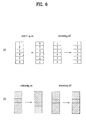
- FIG. 6 is a diagram illustrating a concept of subband based mirroring in accordance with one embodiment of the present invention.
- (a) of FIG. 6 illustrates a case where subband based mirroring is performed and a case where subband based mirroring is not performed under the assumption that one subband includes six RBs. Namely, if it is assumed that number within each RB is RB index in (a) of FIG. 6 , RB index is arranged in a reverse order based on a center frequency in the RB within the subband when mirroring is performed within the subband. Meanwhile, (b) of FIG. 6 illustrates a case where transmission packets of different user equipments multiplexed within a specific subband undergo mirroring in next transmission unit and a case where the transmission packets do not undergo mirroring.
- the embodiment of the present invention suggests a method of improving frequency diversity gain and inter-cell interference randomization by combining cell -specific cyclic shift type hopping of the subband unit with on/off of cell-specific mirroring within each subband. More particularly, the embodiment of the present invention suggests that on/off pattern of cell-specific mirroring is equally applied to all subbands for a specific TTI of a specific cell so as to simplify a frequency hopping pattern.
- FIG. 7 is a diagram illustrating an example of combining subband hopping with subband based mirroring in accordance with one embodiment of the present invention.
- the PUSCH transmission band is divided into four subbands.
- a mirroring pattern represents whether a random transmission slot (or subframe) applies mirroring of a previous subband to a previous transmission slot (or subframe).
- a subband hopping pattern represents whether a random transmission slot (or subframe) applies cyclic shift corresponding to several subframes to a previous transmission slot (or subframe).
- subband hopping can be used in such a manner that RB index for cyclic shift is defined based on RB index allocated through scheduling with respect to initial transmission or random retransmission not previous slot (or subframe).
- the amount a t * N RB sb of index cyclically shifted based on the reference index in accordance with subband hopping is represented as m, and the number N sb of subbands is represented as M.
- a method of generating a cell-specific m value sequence between the base station and the user equipment within each cell and a method of generating a cell-specific mirroring on/off sequence are respectively defined. Then, the embodiment of the present invention suggests that frequency hopping transmission and reception are performed by combination of the two sequences. In more detail, the two sequences can be generated using different maximum length sequences.
- the embodiment of the present invention suggests that the value m is defined through the above calculation or another calculation which includes the above calculation.
- m value patterns of different cells can be obtained in such a manner that different phase offsets of the m-sequence generator are given to different cells.
- the mirroring on/off pattern can be defined in such a manner that a value of 0 and a value of 1 are respectively mapped with on/off or off/on with respect to independent m-sequences.
- one bit of the shift register status value used to generate a cyclic shift pattern of a cell-specific subband is used as the mirroring on/off pattern so that load required to generate two independent random sequences is reduced.
- the value m represents the amount of cyclic shift for reference transmission not cyclic shift for previous transmission
- the value m should be changed per transmission so that the value m is not regarded as the same cyclic shift amount as the previous cyclic shift amount, whereby the same subband is not used for continuous transmission.
- M-1 number of m values from 1 to M-1 are generated per transmission time.
- the generated m values are mapped with M-1 number of cyclically shifted values excluding cyclically shifted value mapped with the value m generated at the previous transmission time among M number of cyclically shifted values.
- one of M number of values from 0 to M-1 is generated as the m value. If the same m value as the m value generated during previous transmission is generated, a specific integer b(b ⁇ 0,
- patterns of different cells can be obtained in such a manner that different phase offsets are given to the different cells.
- (M-1)*2 number of m values are divided into M-1 number of pairs mapped with mirroring on and mirroring off within the amount of a single subband cyclic shift.
- M-1 number of possible m value pairs should be changed per transmission so that the m values are not regarded as the same cyclic shift amount as the previous cyclic shift amount, thereby preventing signal transmission from being performed through a single subband in continuous transmission.
- the m value pairs are mapped with the subband cyclically shifted values so that the m values generated per transmission time are mapped with M-1 number of cyclically shifted values excluding cyclically shifted value mapped with the m value generated at the previous transmission time among M number of cyclically shifted values.
- one of 2M number of values from 0 to 2M-1 is generated as the m value. If the same m value, which is mapped with cyclic shift, as the m value generated during previous transmission is generated, a specific integer b(b ⁇ 0,
- the number of RBs within each subband may be different from that within another subband if the number of RBs of the data transmission band is not divided exactly by M.
- the reason why that frequency hopping is defined in subband unit in the SC-FDMA system is that packet transmission of one user equipment is performed through continuous subcarriers to maintain a low PAPR feature.
- RB' the number of RBs in a subband of a minimum bandwidth is defined as RB', it is preferably limited that RBs less than RB' are only allocated for packet transmission to which frequency hopping pattern using subband is applied.
- the aforementioned frequency hopping pattern can be used for each interlace where HARQ process is operated, or can be used in slot unit within each interlace.
- a hopping sequence pattern is preferably operated for each interlace where HARQ process is operated.
- FIG. 8 is a diagram illustrating a concept of frequency hopping performed for each interlace for HARQ process in accordance with one embodiment of the present invention.
- FIG. 8 illustrates a case where four HARQ processes are defined in the system and frequency hopping is applied in subframe (or packet) unit.
- the hopping pattern sequence is operated for each HARQ process.
- one packet is divided into two slots for frequency hopping. At this time, the hopping pattern sequence is operated for each HARQ process in slot unit.
- m(n) is an output value using a generator which generates integers more than 0.
- the generator could be m- sequence generator.
- different cells may have different initial values (or phase values) of a shift register which includes m-sequence generator.
Landscapes
- Engineering & Computer Science (AREA)
- Signal Processing (AREA)
- Computer Networks & Wireless Communication (AREA)
- Mobile Radio Communication Systems (AREA)
Claims (11)
- Procédé de transmission de signaux de liaison montante à partir d'un équipement utilisateur vers une station de base par une unité de transmission de domaine temporel d'une taille prédéterminée, le procédé étant caractérisé en ce qu'il comprend les étapes consistant à :recevoir des informations d'autorisation de programmation de liaison montante concernant l'application ou non du saut de fréquence ;mapper les signaux de liaison montante sur des blocs de ressources par l'unité de transmission de domaine temporel en fonction d'une configuration de saut de fréquence prédéterminée à l'aide d'un saut de sous-bande, si les informations d'autorisation de programmation de liaison montante reçues indiquent d'appliquer le saut de sous-bande,dans lequel une bande de système destinée à une transmission des signaux de liaison montante comprend
 dans lequel chacune des sous-bandes comprend
 dans lequel chacun des
 transmettre les signaux de liaison montante mappés sur le bloc de ressources à la station de base,dans lequel le saut de sous-bande est défini de sorte que les blocs de ressources à utiliser pour mapper les signaux de liaison montante sont donnés à l'aide d'un indice de RB(t), dans lequel :
 dans lequel t indique un indice de l'unité de transmission de domaine temporel, etdans lequel a(t) indique une valeur de nombre entier aléatoire.
 - Procédé selon la revendication 1, dans lequel le saut de sous-bande s'applique de manière égale à la transmission de signaux de liaison montante de tous les équipements utilisateurs à l'intérieur d'une cellule.
- Procédé selon la revendication 1, dans lequel l'indice de référence prédéterminé est déterminé sous la forme RB(t-1) ou sous la forme d'un indice de bloc de ressources programmé à partir d'une station de base.
- Procédé selon la revendication 1, dans lequel la valeur de nombre entier aléatoire de (a)t est générée sous forme d'une valeur aléatoire spécifique à la cellule.
- Procédé selon la revendication 4, dans lequel la valeur aléatoire spécifique à la cellule est donnée par un générateur de séquence m qui utilise des informations spécifiques à la cellule en tant que valeur initiale.
- Procédé selon la revendication 5, dans lequel la valeur de nombre entier aléatoire de a(t) est donnée par une opération de calcul qui comprend :l'exécution d'un calcul modulaire de :(une valeur d'état (a) d'un registre de décalage du générateur de séquence m) mod (Nsb -1) ; etl'ajout de 1 à la valeur calculée modulaire.
- Procédé selon la revendication 1, dans lequel les blocs de ressources utilisés pour mapper les signaux de liaison montante d'un équipement utilisateur sont situés dans une seule sous-bande.
- Procédé selon la revendication 1, dans lequel la configuration de saut de fréquence prédéterminée est définie pour utiliser en outre la réflexion qui permet à

- Procédé selon la revendication 1, dans lequel l'unité de transmission de domaine temporel représente un intervalle ou une sous-trame.
- Procédé selon la revendication 1, dans lequel un saut de fréquence selon la configuration de saut de fréquence prédéterminée est utilisé dans une unité d'une unité d'entrelacement dans laquelle un processus de demande de répétition automatique hybride HARQ (hybrid automatic repeat request) est mis en oeuvre.
- Équipement utilisateur permettant de transmettre des signaux de liaison montante à une station de base par une unité de transmission de domaine temporel d'une taille prédéterminée,
l'équipement utilisateur étant adapté pour exécuter le procédé selon l'une quelconque des revendications 1 à 10.
Priority Applications (1)
| Application Number | Priority Date | Filing Date | Title |
|---|---|---|---|
| EP15002791.0A EP2991240B1 (fr) | 2007-10-01 | 2008-10-01 | Configuration de sauts de fréquence et procédé de transmission de signaux de liaison montante à l'aide de celle-ci |
Applications Claiming Priority (7)
| Application Number | Priority Date | Filing Date | Title |
|---|---|---|---|
| US97657907P | 2007-10-01 | 2007-10-01 | |
| US98243407P | 2007-10-25 | 2007-10-25 | |
| US99118307P | 2007-11-29 | 2007-11-29 | |
| US1203007P | 2007-12-06 | 2007-12-06 | |
| US1442807P | 2007-12-17 | 2007-12-17 | |
| KR1020080095842A KR101448653B1 (ko) | 2007-10-01 | 2008-09-30 | 주파수 호핑 패턴 및 이를 이용한 상향링크 신호 전송 방법 |
| PCT/KR2008/005776 WO2009045044A1 (fr) | 2007-10-01 | 2008-10-01 | Configuration de sauts de fréquence et procédé de transmission de signaux de liaison montante utilisant une telle configuration |
Related Child Applications (2)
| Application Number | Title | Priority Date | Filing Date |
|---|---|---|---|
| EP15002791.0A Division EP2991240B1 (fr) | 2007-10-01 | 2008-10-01 | Configuration de sauts de fréquence et procédé de transmission de signaux de liaison montante à l'aide de celle-ci |
| EP15002791.0A Division-Into EP2991240B1 (fr) | 2007-10-01 | 2008-10-01 | Configuration de sauts de fréquence et procédé de transmission de signaux de liaison montante à l'aide de celle-ci |
Publications (3)
| Publication Number | Publication Date |
|---|---|
| EP2195940A1 EP2195940A1 (fr) | 2010-06-16 |
| EP2195940A4 EP2195940A4 (fr) | 2010-12-01 |
| EP2195940B1 true EP2195940B1 (fr) | 2015-12-09 |
Family
ID=40759961
Family Applications (2)
| Application Number | Title | Priority Date | Filing Date |
|---|---|---|---|
| EP08835864.3A Active EP2195940B1 (fr) | 2007-10-01 | 2008-10-01 | Configuration de sauts de fréquence et procédé de transmission de signaux de liaison montante utilisant une telle configuration |
| EP15002791.0A Active EP2991240B1 (fr) | 2007-10-01 | 2008-10-01 | Configuration de sauts de fréquence et procédé de transmission de signaux de liaison montante à l'aide de celle-ci |
Family Applications After (1)
| Application Number | Title | Priority Date | Filing Date |
|---|---|---|---|
| EP15002791.0A Active EP2991240B1 (fr) | 2007-10-01 | 2008-10-01 | Configuration de sauts de fréquence et procédé de transmission de signaux de liaison montante à l'aide de celle-ci |
Country Status (8)
| Country | Link |
|---|---|
| US (4) | US8416835B2 (fr) |
| EP (2) | EP2195940B1 (fr) |
| JP (2) | JP5185387B2 (fr) |
| KR (1) | KR101448653B1 (fr) |
| CN (1) | CN101816133B (fr) |
| ES (1) | ES2559423T3 (fr) |
| TW (1) | TWI404351B (fr) |
| WO (1) | WO2009045044A1 (fr) |
Families Citing this family (54)
| Publication number | Priority date | Publication date | Assignee | Title |
|---|---|---|---|---|
| GB2446197A (en) | 2007-02-05 | 2008-08-06 | Nec Corp | Frequency-hopping method and mobile communication system |
| KR101448653B1 (ko) | 2007-10-01 | 2014-10-15 | 엘지전자 주식회사 | 주파수 호핑 패턴 및 이를 이용한 상향링크 신호 전송 방법 |
| KR101534169B1 (ko) | 2008-12-23 | 2015-07-07 | 삼성전자 주식회사 | 주파수 도약 모드로 동작 중인 무선 통신 시스템의 주파수 할당 방법 및 이를 위한 장치 |
| US9374131B2 (en) * | 2009-01-28 | 2016-06-21 | Qualcomm Incorporated | Frequency hopping in a wireless communication network |
| WO2010087449A1 (fr) * | 2009-02-02 | 2010-08-05 | 株式会社 エヌ・ティ・ティ・ドコモ | Appareil de station de base et procédé dans un système de communication mobile |
| EP2386179B1 (fr) * | 2009-04-24 | 2014-09-17 | Huawei Technologies Co., Ltd. | Procédé de génération de signaux de référence |
| CA2761636C (fr) * | 2009-05-29 | 2016-12-06 | Panasonic Corporation | Procede de saut de frequence et appareil de communication sans fil |
| US20120115526A1 (en) * | 2009-08-07 | 2012-05-10 | Panasonic Corporation | Radio base station and radio communication method |
| US9131395B2 (en) * | 2010-09-08 | 2015-09-08 | Broadcom Corporation | Acknowledgment and/or receiver recovery mechanisms for scheduled responses within multiple user, multiple access, and/or MIMO wireless communications |
| US9059756B2 (en) | 2010-11-09 | 2015-06-16 | Qualcomm Incorporated | Using precoding vector switching in uplink shared channel |
| US20140119339A1 (en) * | 2011-04-25 | 2014-05-01 | Lg Electronics Inc. | Method for controlling error for carrier aggregation and apparatus for same |
| US20120307870A1 (en) * | 2011-06-03 | 2012-12-06 | Renesas Mobile Corporation | Apparatus and method for communication |
| CN107659390B (zh) | 2012-02-20 | 2021-01-01 | Lg 电子株式会社 | 无线通信系统中传送上行链路信号的方法和设备 |
| EP2817933B1 (fr) | 2012-02-20 | 2020-04-01 | LG Electronics Inc. | Procédé et appareil d'émission d'un signal montant dans un système de communication sans fil |
| WO2013125843A1 (fr) | 2012-02-20 | 2013-08-29 | 엘지전자 주식회사 | Procédé et appareil d'émission d'un signal montant dans un système de communication sans fil |
| WO2014007531A1 (fr) * | 2012-07-05 | 2014-01-09 | 주식회사 케이티 | Procédé de commande de transmission en liaison montante dans un réseau de communication mobile et appareil associé |
| KR101669710B1 (ko) | 2012-07-05 | 2016-10-26 | 주식회사 케이티 | 이동통신망에서의 상향링크 전송 제어 방법과 그 장치 |
| CN103580832B (zh) * | 2012-07-25 | 2019-01-11 | 中兴通讯股份有限公司 | 数据传输方法及装置 |
| FR2995115B1 (fr) * | 2012-09-04 | 2014-09-05 | Sigfox | Procedes d'emission et de reception de donnees dans un systeme de telecommunications numeriques |
| US9572055B2 (en) * | 2013-04-09 | 2017-02-14 | Spectrum Effect, Inc. | Uplink interference detection using transmission matrices |
| WO2015099808A1 (fr) * | 2013-12-28 | 2015-07-02 | Intel IP Corporation | Procédés et agencements pour accroître la portée d'émission |
| KR102234813B1 (ko) * | 2014-03-31 | 2021-04-01 | 후지츠 코네쿠텟도 테크노로지즈 가부시키가이샤 | 신호 재송신 장치 및 방법 및 통신 시스템 |
| CN105101419B (zh) * | 2014-05-08 | 2018-09-07 | 电信科学技术研究院 | 一种信号传输的方法及终端 |
| US9608690B2 (en) * | 2014-07-17 | 2017-03-28 | Qualcomm Incorporated | Type 1 and type 2 hopping for device-to-device communications |
| WO2016159611A1 (fr) * | 2015-03-27 | 2016-10-06 | 엘지전자 주식회사 | Procédé et dispositif de transmission et de réception de signal dans un système de communication sans fil |
| KR101923456B1 (ko) * | 2015-04-03 | 2018-11-29 | 엘지전자 주식회사 | 무선 통신 시스템에서 신호를 송수신하는 방법 및 이를 위한 장치 |
| EP3300286B1 (fr) * | 2015-05-18 | 2023-05-10 | Samsung Electronics Co., Ltd. | Procédé et appareil destinés à une communication en réseau iot cellulaire |
| WO2017034096A1 (fr) * | 2015-08-21 | 2017-03-02 | 엘지전자(주) | Procédé de transmission et de réception de données de liaison descendante dans un système de communication sans fil, et appareil associé |
| US11177853B2 (en) * | 2015-11-13 | 2021-11-16 | Xi'an Zhongxing New Software Co., Ltd. | Information transmission method and apparatus |
| US10135596B2 (en) * | 2016-01-20 | 2018-11-20 | Qualcomm Incorporated | Narrow band ACK / NACK transmissions |
| US20170223695A1 (en) * | 2016-02-03 | 2017-08-03 | Lg Electronics Inc. | Method and apparatus for transmitting an uplink channel in a wireless communication system |
| US10412755B2 (en) * | 2016-03-25 | 2019-09-10 | Qualcomm Incorporated | Techniques for configuring uplink transmissions in a shared radio frequency spectrum band |
| US10505697B2 (en) * | 2016-11-03 | 2019-12-10 | At&T Intellectual Property I, L.P. | Facilitating a mobile device specific physical downlink shared channel resource element mapping indicator |
| US11546929B2 (en) | 2017-01-09 | 2023-01-03 | Huawei Technologies Co., Ltd. | Systems and methods for signaling for semi-static configuration in grant-free uplink transmissions |
| CN108633033B (zh) * | 2017-03-24 | 2023-05-12 | 中兴通讯股份有限公司 | 一种传输资源确定方法、装置及用户设备 |
| US10645730B2 (en) * | 2017-04-06 | 2020-05-05 | Huawei Technologies Co., Ltd. | Flexible grant-free resource configuration signaling |
| CN116056234B (zh) * | 2017-06-16 | 2025-08-19 | Lg电子株式会社 | 发送和接收物理上行链路控制信道的方法及其装置 |
| US10667282B2 (en) * | 2017-07-11 | 2020-05-26 | Qualcomm Incorporated | Uplink hopping pattern modes for hybrid automatic repeat request (HARQ) transmissions |
| CN109548162B (zh) * | 2017-08-07 | 2021-12-03 | 珠海市魅族科技有限公司 | 低时延业务控制信道设计方法、低延时终端及基站 |
| CN109428626B (zh) | 2017-09-05 | 2021-02-12 | 华为技术有限公司 | 一种信号传输方法、相关设备及系统 |
| WO2019047171A1 (fr) | 2017-09-08 | 2019-03-14 | Oppo广东移动通信有限公司 | Procédé et dispositif de détermination de sauts de fréquence de canal, et support de stockage informatique |
| EP3664315B1 (fr) | 2017-09-08 | 2022-04-27 | Guangdong Oppo Mobile Telecommunications Corp., Ltd. | Procédé et appareil pour déterminer un saut de fréquence de canal, et support de stockage informatique |
| CN109511171B (zh) * | 2017-09-15 | 2022-04-12 | 华为技术有限公司 | 一种通信方法及设备 |
| CN109600211B (zh) * | 2017-09-30 | 2024-06-07 | 中兴通讯股份有限公司 | 随机接入前导的跳频处理方法和装置、及终端和存储介质 |
| AU2017440171B2 (en) * | 2017-11-16 | 2023-02-02 | Ntt Docomo, Inc. | User terminal and radio communication method |
| CN110430615B (zh) * | 2018-01-12 | 2020-08-21 | 华为技术有限公司 | 信道状态信息上报频带的配置方法及通信装置 |
| US10547347B2 (en) | 2018-01-12 | 2020-01-28 | At&T Intellectual Property I, L.P. | Uplink coverage for 5G or other next generation network using multi-slot frequency hopping |
| WO2020060027A1 (fr) * | 2018-09-20 | 2020-03-26 | 엘지전자 주식회사 | Procédé de transmission d'informations de planification concernant un fonctionnement v2x dans un système de communication sans fil et terminal utilisant le procédé |
| US10912101B2 (en) * | 2018-11-12 | 2021-02-02 | General Electric Company | Frequency-based communication system and method |
| EP3911054A4 (fr) * | 2019-02-03 | 2021-12-29 | Huawei Technologies Co., Ltd. | Procédés, appareils et systèmes de réception et d'émission de signal de référence |
| US12095683B2 (en) * | 2019-02-14 | 2024-09-17 | Ntt Docomo, Inc. | User terminal |
| KR102214083B1 (ko) | 2019-02-15 | 2021-02-10 | 엘지전자 주식회사 | 무선 통신 시스템에서 무선 신호 송수신 방법 및 장치 |
| KR102725041B1 (ko) * | 2020-09-21 | 2024-10-31 | 주식회사 엘지에너지솔루션 | 배터리 팩 내부에서 무선 통신 방법 및 그 방법을 제공하는 마스터 bms |
| US11502721B2 (en) * | 2021-03-25 | 2022-11-15 | Qualcomm Incorporated | Frequency hopping techniques for uplink control channel repetitions |
Family Cites Families (17)
| Publication number | Priority date | Publication date | Assignee | Title |
|---|---|---|---|---|
| KR100365789B1 (ko) * | 1998-01-20 | 2003-05-09 | 삼성전자 주식회사 | 병렬도약직접시퀀스/느린주파수도약복합코드분할다중접속시스템 |
| DE60103459T2 (de) | 2000-08-02 | 2005-08-04 | Lucent Technologies Inc. | Verfahren zur Verbesserung der Leistung eines GSM Erzeuger von Frequenzsprungsequenzen für Kanälen mit halb und viertel Rat |
| US7054346B2 (en) * | 2001-05-07 | 2006-05-30 | Lucent Technologies Inc. | Enhanced frequency hopping in a wireless system |
| DE10211235B4 (de) | 2002-03-13 | 2010-11-11 | Abb Research Ltd. | Verfahren zur Generierung einer Frequency Hopping Frequenzfolge |
| US7177297B2 (en) * | 2003-05-12 | 2007-02-13 | Qualcomm Incorporated | Fast frequency hopping with a code division multiplexed pilot in an OFDMA system |
| UA88873C2 (ru) * | 2003-05-12 | 2009-12-10 | Квелкомм Инкорпорейтед | Способы и устройства для передачи и приема пилот-сигнала и данных с быстрой скачкообразной перестройкой частоты с мультиплексированием с кодовым разделением пилот-сигналом в системе мдочр |
| JP4478775B2 (ja) * | 2003-07-31 | 2010-06-09 | 財団法人名古屋産業科学研究所 | 増殖制御型組換えアデノウイルスベクターの効率的な作製方法及びその作製用キット |
| US7580444B2 (en) * | 2004-05-04 | 2009-08-25 | Her Majesty The Queen In Right Of Canada, As Represented By The Minister Of Industry, Through The Communications Research Centre Canada | Frequency hopping communication system |
| US8014781B2 (en) * | 2004-06-08 | 2011-09-06 | Qualcomm Incorporated | Intra-cell common reuse for a wireless communications system |
| KR101119275B1 (ko) * | 2005-07-15 | 2012-03-16 | 삼성전자주식회사 | 직교 주파수 분할 다중 접속 방식을 사용하는 통신시스템에서 채널 구성 방법과 그 송수신 장치 및 방법 |
| KR100995830B1 (ko) * | 2005-09-26 | 2010-11-23 | 삼성전자주식회사 | 이동 통신 시스템에서 채널 상태 정보를 이용한 데이터 송수신 방법 및 시스템 |
| US10084627B2 (en) * | 2006-07-10 | 2018-09-25 | Qualcomm Incorporated | Frequency hopping in an SC-FDMA environment |
| EP1944875B1 (fr) * | 2007-01-09 | 2018-11-14 | Samsung Electronics Co., Ltd. | Appareil et procédé d'attribution de ressources dans un système d'accès multiple par répartition en fréquence de transporteur unique |
| GB2446197A (en) * | 2007-02-05 | 2008-08-06 | Nec Corp | Frequency-hopping method and mobile communication system |
| KR101448653B1 (ko) * | 2007-10-01 | 2014-10-15 | 엘지전자 주식회사 | 주파수 호핑 패턴 및 이를 이용한 상향링크 신호 전송 방법 |
| CN101159460A (zh) * | 2007-10-29 | 2008-04-09 | 中兴通讯股份有限公司 | 跳频序列生成方法 |
| US9374131B2 (en) * | 2009-01-28 | 2016-06-21 | Qualcomm Incorporated | Frequency hopping in a wireless communication network |
-
2008
- 2008-09-30 KR KR1020080095842A patent/KR101448653B1/ko active Active
- 2008-10-01 CN CN2008801098851A patent/CN101816133B/zh active Active
- 2008-10-01 US US12/680,989 patent/US8416835B2/en active Active
- 2008-10-01 WO PCT/KR2008/005776 patent/WO2009045044A1/fr not_active Ceased
- 2008-10-01 TW TW097137758A patent/TWI404351B/zh active
- 2008-10-01 JP JP2010527884A patent/JP5185387B2/ja active Active
- 2008-10-01 ES ES08835864.3T patent/ES2559423T3/es active Active
- 2008-10-01 EP EP08835864.3A patent/EP2195940B1/fr active Active
- 2008-10-01 EP EP15002791.0A patent/EP2991240B1/fr active Active
-
2012
- 2012-04-23 US US13/453,988 patent/US8817739B2/en active Active
- 2012-10-19 JP JP2012231614A patent/JP5620453B2/ja active Active
-
2014
- 2014-07-11 US US14/329,218 patent/US9590693B2/en active Active
-
2017
- 2017-01-24 US US15/414,280 patent/US10084508B2/en active Active
Also Published As
| Publication number | Publication date |
|---|---|
| EP2991240A1 (fr) | 2016-03-02 |
| JP2010541458A (ja) | 2010-12-24 |
| EP2195940A1 (fr) | 2010-06-16 |
| CN101816133B (zh) | 2013-10-30 |
| WO2009045044A1 (fr) | 2009-04-09 |
| EP2991240B1 (fr) | 2018-04-25 |
| US10084508B2 (en) | 2018-09-25 |
| JP2013048466A (ja) | 2013-03-07 |
| US20100284363A1 (en) | 2010-11-11 |
| US20140321510A1 (en) | 2014-10-30 |
| US8817739B2 (en) | 2014-08-26 |
| US9590693B2 (en) | 2017-03-07 |
| ES2559423T3 (es) | 2016-02-12 |
| JP5620453B2 (ja) | 2014-11-05 |
| JP5185387B2 (ja) | 2013-04-17 |
| KR101448653B1 (ko) | 2014-10-15 |
| CN101816133A (zh) | 2010-08-25 |
| US8416835B2 (en) | 2013-04-09 |
| US20170134068A1 (en) | 2017-05-11 |
| TW200922160A (en) | 2009-05-16 |
| EP2195940A4 (fr) | 2010-12-01 |
| US20120263142A1 (en) | 2012-10-18 |
| TWI404351B (zh) | 2013-08-01 |
| KR20090033802A (ko) | 2009-04-06 |
Similar Documents
| Publication | Publication Date | Title |
|---|---|---|
| EP2195940B1 (fr) | Configuration de sauts de fréquence et procédé de transmission de signaux de liaison montante utilisant une telle configuration | |
| US12177149B2 (en) | Transmitter, receiver, transmission method, and reception method | |
| EP1944875B1 (fr) | Appareil et procédé d'attribution de ressources dans un système d'accès multiple par répartition en fréquence de transporteur unique | |
| EP3253000B1 (fr) | Technique de saut de fréquence pour liaison montante e-utra | |
| EP2493089B1 (fr) | Appareil et procédé de transmission de signal de référence de sondage de liaison montante dans des systèmes de communication sans fil à antennes multiples et saut de signal de référence de sondage | |
| US8885743B2 (en) | Method of transmitting control signal in wireless communication system | |
| EP2062408B1 (fr) | Procédé et appareil pour transmettre un signal de liaison montante, et procédé et appareil pour générer un signal de liaison montante dans un système de communication | |
| KR20080096334A (ko) | 무선통신 시스템에서 상향링크 채널사운딩 레퍼런스 신호의송수신 방법 |
Legal Events
| Date | Code | Title | Description |
|---|---|---|---|
| PUAI | Public reference made under article 153(3) epc to a published international application that has entered the european phase |
Free format text: ORIGINAL CODE: 0009012 |
|
| 17P | Request for examination filed |
Effective date: 20100414 |
|
| AK | Designated contracting states |
Kind code of ref document: A1 Designated state(s): AT BE BG CH CY CZ DE DK EE ES FI FR GB GR HR HU IE IS IT LI LT LU LV MC MT NL NO PL PT RO SE SI SK TR |
|
| AX | Request for extension of the european patent |
Extension state: AL BA MK RS |
|
| A4 | Supplementary search report drawn up and despatched |
Effective date: 20101028 |
|
| RIC1 | Information provided on ipc code assigned before grant |
Ipc: H04B 7/12 20060101AFI20090427BHEP Ipc: H04W 16/02 20090101ALI20101022BHEP Ipc: H04B 1/713 20060101ALI20101022BHEP |
|
| DAX | Request for extension of the european patent (deleted) | ||
| GRAP | Despatch of communication of intention to grant a patent |
Free format text: ORIGINAL CODE: EPIDOSNIGR1 |
|
| INTG | Intention to grant announced |
Effective date: 20150624 |
|
| GRAS | Grant fee paid |
Free format text: ORIGINAL CODE: EPIDOSNIGR3 |
|
| GRAA | (expected) grant |
Free format text: ORIGINAL CODE: 0009210 |
|
| AK | Designated contracting states |
Kind code of ref document: B1 Designated state(s): AT BE BG CH CY CZ DE DK EE ES FI FR GB GR HR HU IE IS IT LI LT LU LV MC MT NL NO PL PT RO SE SI SK TR |
|
| REG | Reference to a national code |
Ref country code: GB Ref legal event code: FG4D |
|
| REG | Reference to a national code |
Ref country code: AT Ref legal event code: REF Ref document number: 764962 Country of ref document: AT Kind code of ref document: T Effective date: 20151215 Ref country code: CH Ref legal event code: EP |
|
| REG | Reference to a national code |
Ref country code: IE Ref legal event code: FG4D |
|
| REG | Reference to a national code |
Ref country code: DE Ref legal event code: R096 Ref document number: 602008041587 Country of ref document: DE |
|
| REG | Reference to a national code |
Ref country code: SE Ref legal event code: TRGR |
|
| REG | Reference to a national code |
Ref country code: ES Ref legal event code: FG2A Ref document number: 2559423 Country of ref document: ES Kind code of ref document: T3 Effective date: 20160212 |
|
| REG | Reference to a national code |
Ref country code: NL Ref legal event code: FP |
|
| REG | Reference to a national code |
Ref country code: LT Ref legal event code: MG4D |
|
| PG25 | Lapsed in a contracting state [announced via postgrant information from national office to epo] |
Ref country code: LT Free format text: LAPSE BECAUSE OF FAILURE TO SUBMIT A TRANSLATION OF THE DESCRIPTION OR TO PAY THE FEE WITHIN THE PRESCRIBED TIME-LIMIT Effective date: 20151209 Ref country code: NO Free format text: LAPSE BECAUSE OF FAILURE TO SUBMIT A TRANSLATION OF THE DESCRIPTION OR TO PAY THE FEE WITHIN THE PRESCRIBED TIME-LIMIT Effective date: 20160309 |
|
| REG | Reference to a national code |
Ref country code: AT Ref legal event code: MK05 Ref document number: 764962 Country of ref document: AT Kind code of ref document: T Effective date: 20151209 |
|
| PG25 | Lapsed in a contracting state [announced via postgrant information from national office to epo] |
Ref country code: GR Free format text: LAPSE BECAUSE OF FAILURE TO SUBMIT A TRANSLATION OF THE DESCRIPTION OR TO PAY THE FEE WITHIN THE PRESCRIBED TIME-LIMIT Effective date: 20160310 Ref country code: LV Free format text: LAPSE BECAUSE OF FAILURE TO SUBMIT A TRANSLATION OF THE DESCRIPTION OR TO PAY THE FEE WITHIN THE PRESCRIBED TIME-LIMIT Effective date: 20151209 |
|
| PG25 | Lapsed in a contracting state [announced via postgrant information from national office to epo] |
Ref country code: IS Free format text: LAPSE BECAUSE OF FAILURE TO SUBMIT A TRANSLATION OF THE DESCRIPTION OR TO PAY THE FEE WITHIN THE PRESCRIBED TIME-LIMIT Effective date: 20151209 |
|
| PG25 | Lapsed in a contracting state [announced via postgrant information from national office to epo] |
Ref country code: CZ Free format text: LAPSE BECAUSE OF FAILURE TO SUBMIT A TRANSLATION OF THE DESCRIPTION OR TO PAY THE FEE WITHIN THE PRESCRIBED TIME-LIMIT Effective date: 20151209 |
|
| PG25 | Lapsed in a contracting state [announced via postgrant information from national office to epo] |
Ref country code: AT Free format text: LAPSE BECAUSE OF FAILURE TO SUBMIT A TRANSLATION OF THE DESCRIPTION OR TO PAY THE FEE WITHIN THE PRESCRIBED TIME-LIMIT Effective date: 20151209 Ref country code: PT Free format text: LAPSE BECAUSE OF FAILURE TO SUBMIT A TRANSLATION OF THE DESCRIPTION OR TO PAY THE FEE WITHIN THE PRESCRIBED TIME-LIMIT Effective date: 20160411 Ref country code: IS Free format text: LAPSE BECAUSE OF FAILURE TO SUBMIT A TRANSLATION OF THE DESCRIPTION OR TO PAY THE FEE WITHIN THE PRESCRIBED TIME-LIMIT Effective date: 20160409 Ref country code: SK Free format text: LAPSE BECAUSE OF FAILURE TO SUBMIT A TRANSLATION OF THE DESCRIPTION OR TO PAY THE FEE WITHIN THE PRESCRIBED TIME-LIMIT Effective date: 20151209 Ref country code: EE Free format text: LAPSE BECAUSE OF FAILURE TO SUBMIT A TRANSLATION OF THE DESCRIPTION OR TO PAY THE FEE WITHIN THE PRESCRIBED TIME-LIMIT Effective date: 20151209 Ref country code: RO Free format text: LAPSE BECAUSE OF FAILURE TO SUBMIT A TRANSLATION OF THE DESCRIPTION OR TO PAY THE FEE WITHIN THE PRESCRIBED TIME-LIMIT Effective date: 20151209 |
|
| REG | Reference to a national code |
Ref country code: FR Ref legal event code: PLFP Year of fee payment: 9 Ref country code: DE Ref legal event code: R097 Ref document number: 602008041587 Country of ref document: DE |
|
| PLBE | No opposition filed within time limit |
Free format text: ORIGINAL CODE: 0009261 |
|
| STAA | Information on the status of an ep patent application or granted ep patent |
Free format text: STATUS: NO OPPOSITION FILED WITHIN TIME LIMIT |
|
| PG25 | Lapsed in a contracting state [announced via postgrant information from national office to epo] |
Ref country code: DK Free format text: LAPSE BECAUSE OF FAILURE TO SUBMIT A TRANSLATION OF THE DESCRIPTION OR TO PAY THE FEE WITHIN THE PRESCRIBED TIME-LIMIT Effective date: 20151209 Ref country code: PL Free format text: LAPSE BECAUSE OF FAILURE TO SUBMIT A TRANSLATION OF THE DESCRIPTION OR TO PAY THE FEE WITHIN THE PRESCRIBED TIME-LIMIT Effective date: 20151209 |
|
| 26N | No opposition filed |
Effective date: 20160912 |
|
| PG25 | Lapsed in a contracting state [announced via postgrant information from national office to epo] |
Ref country code: SI Free format text: LAPSE BECAUSE OF FAILURE TO SUBMIT A TRANSLATION OF THE DESCRIPTION OR TO PAY THE FEE WITHIN THE PRESCRIBED TIME-LIMIT Effective date: 20151209 |
|
| PG25 | Lapsed in a contracting state [announced via postgrant information from national office to epo] |
Ref country code: BE Free format text: LAPSE BECAUSE OF FAILURE TO SUBMIT A TRANSLATION OF THE DESCRIPTION OR TO PAY THE FEE WITHIN THE PRESCRIBED TIME-LIMIT Effective date: 20151209 |
|
| REG | Reference to a national code |
Ref country code: CH Ref legal event code: PL |
|
| REG | Reference to a national code |
Ref country code: IE Ref legal event code: MM4A |
|
| PG25 | Lapsed in a contracting state [announced via postgrant information from national office to epo] |
Ref country code: LI Free format text: LAPSE BECAUSE OF NON-PAYMENT OF DUE FEES Effective date: 20161031 Ref country code: CH Free format text: LAPSE BECAUSE OF NON-PAYMENT OF DUE FEES Effective date: 20161031 |
|
| PG25 | Lapsed in a contracting state [announced via postgrant information from national office to epo] |
Ref country code: LU Free format text: LAPSE BECAUSE OF NON-PAYMENT OF DUE FEES Effective date: 20161001 |
|
| REG | Reference to a national code |
Ref country code: FR Ref legal event code: PLFP Year of fee payment: 10 |
|
| PG25 | Lapsed in a contracting state [announced via postgrant information from national office to epo] |
Ref country code: IE Free format text: LAPSE BECAUSE OF NON-PAYMENT OF DUE FEES Effective date: 20161001 |
|
| PG25 | Lapsed in a contracting state [announced via postgrant information from national office to epo] |
Ref country code: CY Free format text: LAPSE BECAUSE OF FAILURE TO SUBMIT A TRANSLATION OF THE DESCRIPTION OR TO PAY THE FEE WITHIN THE PRESCRIBED TIME-LIMIT Effective date: 20151209 Ref country code: HU Free format text: LAPSE BECAUSE OF FAILURE TO SUBMIT A TRANSLATION OF THE DESCRIPTION OR TO PAY THE FEE WITHIN THE PRESCRIBED TIME-LIMIT; INVALID AB INITIO Effective date: 20081001 |
|
| PG25 | Lapsed in a contracting state [announced via postgrant information from national office to epo] |
Ref country code: TR Free format text: LAPSE BECAUSE OF FAILURE TO SUBMIT A TRANSLATION OF THE DESCRIPTION OR TO PAY THE FEE WITHIN THE PRESCRIBED TIME-LIMIT Effective date: 20151209 Ref country code: MT Free format text: LAPSE BECAUSE OF NON-PAYMENT OF DUE FEES Effective date: 20161031 Ref country code: HR Free format text: LAPSE BECAUSE OF FAILURE TO SUBMIT A TRANSLATION OF THE DESCRIPTION OR TO PAY THE FEE WITHIN THE PRESCRIBED TIME-LIMIT Effective date: 20151209 Ref country code: MC Free format text: LAPSE BECAUSE OF FAILURE TO SUBMIT A TRANSLATION OF THE DESCRIPTION OR TO PAY THE FEE WITHIN THE PRESCRIBED TIME-LIMIT Effective date: 20151209 |
|
| PG25 | Lapsed in a contracting state [announced via postgrant information from national office to epo] |
Ref country code: BG Free format text: LAPSE BECAUSE OF FAILURE TO SUBMIT A TRANSLATION OF THE DESCRIPTION OR TO PAY THE FEE WITHIN THE PRESCRIBED TIME-LIMIT Effective date: 20151209 |
|
| REG | Reference to a national code |
Ref country code: FR Ref legal event code: PLFP Year of fee payment: 11 |
|
| P01 | Opt-out of the competence of the unified patent court (upc) registered |
Effective date: 20230610 |
|
| PGFP | Annual fee paid to national office [announced via postgrant information from national office to epo] |
Ref country code: FI Payment date: 20250908 Year of fee payment: 18 |
|
| PGFP | Annual fee paid to national office [announced via postgrant information from national office to epo] |
Ref country code: NL Payment date: 20250909 Year of fee payment: 18 Ref country code: IT Payment date: 20250909 Year of fee payment: 18 |
|
| PGFP | Annual fee paid to national office [announced via postgrant information from national office to epo] |
Ref country code: GB Payment date: 20250909 Year of fee payment: 18 |
|
| PGFP | Annual fee paid to national office [announced via postgrant information from national office to epo] |
Ref country code: FR Payment date: 20250909 Year of fee payment: 18 |
|
| PGFP | Annual fee paid to national office [announced via postgrant information from national office to epo] |
Ref country code: SE Payment date: 20250909 Year of fee payment: 18 |
|
| PGFP | Annual fee paid to national office [announced via postgrant information from national office to epo] |
Ref country code: DE Payment date: 20250908 Year of fee payment: 18 |
|
| PGFP | Annual fee paid to national office [announced via postgrant information from national office to epo] |
Ref country code: ES Payment date: 20251117 Year of fee payment: 18 |