EP2195975B1 - Fehlerlose und störungslose kommunikation mit variabler datenrate - Google Patents
Fehlerlose und störungslose kommunikation mit variabler datenrate Download PDFInfo
- Publication number
- EP2195975B1 EP2195975B1 EP08808075A EP08808075A EP2195975B1 EP 2195975 B1 EP2195975 B1 EP 2195975B1 EP 08808075 A EP08808075 A EP 08808075A EP 08808075 A EP08808075 A EP 08808075A EP 2195975 B1 EP2195975 B1 EP 2195975B1
- Authority
- EP
- European Patent Office
- Prior art keywords
- channels
- data
- data rate
- variable data
- point
- Prior art date
- Legal status (The legal status is an assumption and is not a legal conclusion. Google has not performed a legal analysis and makes no representation as to the accuracy of the status listed.)
- Not-in-force
Links
Images
Classifications
-
- H—ELECTRICITY
- H04—ELECTRIC COMMUNICATION TECHNIQUE
- H04L—TRANSMISSION OF DIGITAL INFORMATION, e.g. TELEGRAPHIC COMMUNICATION
- H04L12/00—Data switching networks
- H04L12/64—Hybrid switching systems
- H04L12/6418—Hybrid transport
-
- H—ELECTRICITY
- H04—ELECTRIC COMMUNICATION TECHNIQUE
- H04L—TRANSMISSION OF DIGITAL INFORMATION, e.g. TELEGRAPHIC COMMUNICATION
- H04L47/00—Traffic control in data switching networks
- H04L47/10—Flow control; Congestion control
- H04L47/24—Traffic characterised by specific attributes, e.g. priority or QoS
- H04L47/2416—Real-time traffic
-
- H—ELECTRICITY
- H04—ELECTRIC COMMUNICATION TECHNIQUE
- H04W—WIRELESS COMMUNICATION NETWORKS
- H04W28/00—Network traffic management; Network resource management
- H04W28/02—Traffic management, e.g. flow control or congestion control
-
- H—ELECTRICITY
- H04—ELECTRIC COMMUNICATION TECHNIQUE
- H04W—WIRELESS COMMUNICATION NETWORKS
- H04W8/00—Network data management
- H04W8/02—Processing of mobility data, e.g. registration information at HLR [Home Location Register] or VLR [Visitor Location Register]; Transfer of mobility data, e.g. between HLR, VLR or external networks
- H04W8/04—Registration at HLR or HSS [Home Subscriber Server]
-
- H—ELECTRICITY
- H04—ELECTRIC COMMUNICATION TECHNIQUE
- H04W—WIRELESS COMMUNICATION NETWORKS
- H04W28/00—Network traffic management; Network resource management
- H04W28/16—Central resource management; Negotiation of resources or communication parameters, e.g. negotiating bandwidth or QoS [Quality of Service]
- H04W28/18—Negotiating wireless communication parameters
- H04W28/22—Negotiating communication rate
-
- H—ELECTRICITY
- H04—ELECTRIC COMMUNICATION TECHNIQUE
- H04W—WIRELESS COMMUNICATION NETWORKS
- H04W72/00—Local resource management
- H04W72/50—Allocation or scheduling criteria for wireless resources
- H04W72/56—Allocation or scheduling criteria for wireless resources based on priority criteria
- H04W72/566—Allocation or scheduling criteria for wireless resources based on priority criteria of the information or information source or recipient
- H04W72/569—Allocation or scheduling criteria for wireless resources based on priority criteria of the information or information source or recipient of the traffic information
Definitions
- the present invention relates to a system and method for variable data rate communication for use in point-to-point communication systems, and, more particularly but not exclusively, to errorless and hitless communication.
- IP Internet Protocol
- E1 signals usually transmit real time data, such as voice, and are considered high priority signals. Introducing errors, or dropping any data from these signals, should be avoided.
- communication channel in all its forms is used throughout the present specification and claims interchangeably with the terms “channel” and “signal” and their corresponding forms.
- Adaptive Coding and Modulation enables changing data rate of a communication system in response to time varying conditions such as interference and fading.
- ACM is widely used in packet communication protocol systems such as wireless LAN (WiFi) and wireless MAN (WiMAX). Such systems reduce their data rate in response to interference and fading. During the process of reducing the data rate, data packets are typically lost and have to be retransmitted.
- WiFi wireless LAN
- WiMAX wireless MAN
- US Published Patent Application 2006/0077994 of Spindola et al describes systems and methods for adapting a de-jitter buffer to conform to air link conditions.
- An air link characteristic may be detected before that characteristic begins to affect packet delivery, such as by slowing or speeding delivery delay at a subscriber station.
- a receiver-side de-jitter buffer which adds delay to received packets, may adaptively adjust its size based upon the detected air link characteristic, such that the de-jitter buffer is appropriately sized for anticipated data packets before they are received at the subscriber station.
- RTSP Real Time Streaming Protocol
- RTP Real Time Transport Protocol
- RTCP Real Time Control Protocol
- SDP Session Description Protocol
- network congestion is reduced by deliberately failing to transmit packets that are judged to be acoustically similar to adjacent packets; the expectation is that, under these circumstances, traditional packet loss concealment algorithms in the receiving device will construct an acceptably accurate replica of the missing packet.
- the receiving device can reduce the number of packets stored in its jitter buffer, and therefore the latency of the speech signal, by selectively deleting one or more packets within sustained silences or non-varying speech events.
- the ability of the system to drop appropriate packets may be enhanced by taking into account the confidence levels associated with the priority assessments.
- US Published Patent Application No. 2004/0228326 of Pearson describes a method of packetizing digital audio information includes separating a digital audio sample into at least one most significant bit and at least one least significant bit.
- the most significant bit(s) of the digital audio sample are placed into an most significant bit packet that has a high transmission priority.
- the least significant bit(s) of the digital audio sample are placed into an least significant bit packet that has a low transmission priority.
- the present invention seeks to provide an improved system and method for a variable data rate mechanism for use in point-to-point communication systems, providing a flexible path for changing data rate while supporting errorless and hitless communication of high priority signals. No loss of framing synchronization occurs during data rate changes, thereby providing uninterrupted and continuous service.
- data rate in all its forms is used throughout the present specification and claims interchangeably with the terms “transmission data rate”, “receiving data rate”, and their corresponding forms.
- a non-limiting example of a point-to-point communication system is a cellular backhaul point-to-point link.
- Traffic in such a system can comprise different types of data: data packets, such as Ethernet packets; and continuous fixed-data-rate streams, such as, by way of a non-limiting example, E1 communication channels.
- variable data rate communication such as ACM
- continuous fixed-data-rate streams such as E1
- packet communication for a mix of continuous fixed-data-rate streams and packet communication.
- a transmission delay caused by the transmission link may change.
- One possible reason for the transmission delay change is a change of a coding mechanism.
- a change of modulation type such as, by way of a non-limiting example, from 64 QAM (Quadrature Amplitude Modulation) to 16 QAM, can cause a transmission delay change.
- 64 QAM Quadrature Amplitude Modulation
- 16 QAM Quadrature Amplitude Modulation
- each transmitted symbol carries 4 bits instead of 6 bits. If a symbol transmission rate is kept constant, more time is needed to transmit data at 4 bits per symbol than at 6 bits per symbol, thereby increasing the transmission delay.
- maintaining a substantially fixed delay is achieved by having a receiver which includes a delay compensation buffer, which maintains a substantially fixed time delay irrespective of a data rate, that is, amount of data per time unit, flowing through the receiver.
- high priority signals which are designated by the system as do-not-drop are communicated by the system without dropping, without adversely affecting error rate, and without substantially affecting a delay produced by the point-to-point communication for the high priority signals.
- lower priority signals When a need arrives for lowering data rate of the system, lower priority signals may be dropped, while high priority signals are still transmitted albeit possibly using a different coding. The change in data rate and the dropping of some signals do not affect the remaining signals which are still carried.
- a non-limiting example of a need for changing the data rate of the system is when radio transmission is used for the point-to-point communication, and weather changes from fair to rainy, stormy, and so on. Such changes decrease a maximum data rate which can be communicated over the point-to-point communication link.
- the data rate of the system is changed faster than changes in weather, changing, by way of a non-limiting example, in approximately 1 millisecond.
- the combination of the higher priority and lower priority signals provides more efficient use of transmission capacity than a pessimistic, worst-case system, which uses only a guaranteed, worst case, data rate.
- the higher priority and the lower priority signals can optionally be continuous fixed-data-rate streams, such as E1.
- E1 communication are designated as channels which may be dropped, while other E1 communication channels, designated as not-to-drop channels, are still transmitted, without changing transmission delay and without adversely affecting error rate.
- More than two levels of priority are optionally used, so that one or more signals are set up top be highest priority, and other signals are set up to be various values of lower priorities.
- signals are dropped according to order of priority.
- the higher priority and the lower priority signals can optionally be packet-based communication channels, such as Ethernet communication channels.
- Some Ethernet communication channels are set up so they can optionally be dropped, while other Ethernet communication channels are set up so that they remain transmitted, without changing transmission delay and without adversely affecting error rate of the remaining communication channels.
- Within an Ethernet communication channel some Ethernet data packets, according to an associated priority, can optionally be dropped, while other Ethernet data packets, according to an associated priority, remain in transmission, without changing transmission delay of other communication channels and of the transmitted Ethernet data packets and without adversely affecting error rate of remaining transmitted communication channels and Ethernet data packets.
- the higher priority and the lower priority signals can optionally be a mix of continuous fixed-data-rate streams, such as E1, and packet-based communication channels, such as Ethernet communication channels.
- E1 communication channels can optionally be dropped, while other E1 communication channels are still transmitted, without changing transmission delay and without adversely affecting error rate of the remaining communication channels.
- Some Ethernet communication channels can optionally be dropped, and some Ethernet data packets can optionally be dropped, while other Ethernet communication channels and other Ethernet data packets within a same Ethernet communication channel are still transmitted, without changing transmission delay of other communication channels and without adversely affecting error rate of remaining transmitted communication channels.
- variable data rate transmitter configured to receive input of data from a plurality of input channels and transmit at least some of the data over a variable data rate point-to-point communication link, wherein portions of the data are associated with priorities, and the transmitter is configured to change transmission of at least some of the portions of the data, based, at least partly, on the priorities associated with the portions of the data, and on a data rate configured for transmitting the portions of the data over the variable data rate communication link.
- the change of transmission of at least some of the portions of the data includes a dropping of the at least some of the portions of the data from transmission.
- the change of transmission of at least some of the portions of the data includes an adding of the at least some of the portions of the data to transmission.
- a multiplexer configured to multiplex at least some of the portions of the data received from the plurality of input channels.
- an adaptive framer configured to package at least some of the portions of the data in data frames.
- variable data rate transmitter configured to transmit at least some of the portions of the data over the variable data rate communication link.
- the input channels include at least one continuous channel.
- the input channels include at least one packet-based channel.
- variable data rate transmitter is configured to drop packets from, and add packets to, the portions of the data transmitted from the at least one packet based channel.
- the input channels include at least one continuous channel and at least one packet-based channel.
- variable data rate transmitter is configured to drop channels from and add channels to transmission, and to drop packets from, and add packets to, the portions of the data transmitted from the at least one packet based channel.
- variable data rate receiver configured to receive data over a variable data rate point-to-point communication link, including a delay compensation buffer configured to maintain a substantially fixed delay between input of the data into a transmitter transmitting the data and output of the data from the delay compensation buffer, by maintaining a suitable output rate of the data from the delay compensation buffer.
- a deframer configured to extract the data from data frames received by the variable data rate receiver.
- a demultiplexer configured to demultiplex the data and output one or more output channels.
- a system configured to transmit at least some of a plurality of channels over a variable data rate point-to-point communication link
- the system including a variable data rate transmitter configured to receive input of data from a plurality of input channels and transmit at least some of the data over a variable data rate point-to-point communication link, wherein portions of the data are associated with priorities, and the transmitter is configured to change transmission of at least some of the portions of the data, based, at least partly, on the priorities associated with the portions of the data, and on a data rate configured for transmitting the portions of the data over the variable data rate communication link, and a variable data rate receiver configured to receive the at least some of the data over the variable data rate point-to-point communication link, including a delay compensation buffer configured to maintain a substantially fixed delay between input of the at least some of the data into the transmitter and output of the at least some of the data from the delay compensation buffer, by maintaining a suitable output rate of the at least some of the data from the delay compensation buffer.
- the change of transmission of at least some of the portions of the data includes a dropping of the at least some of the portions of the data from transmission.
- the change of transmission of at least some of the portions of the data includes an adding of the at least some of the portions of the data to transmission.
- the portions of the data which are not dropped from transmission maintain a substantially unchanged error rate while the transmitter performs dropping and adding portions of the data from transmission.
- a method for transmitting a plurality of communication channels over a variable data rate point-to-point communication link including receiving input of data from a plurality of input channels, transmitting at least some of the data over the variable data rate point-to-point communication link, determining that the variable data rate has changed, and changing transmission of at least some portions of the data, while maintaining a substantially fixed delay and maintaining an error rate substantially as before, or better, in the portions of the data being transmitted.
- the changing transmission of at least some portions of the data includes a dropping of the at least some portions of the data from transmission.
- the changing transmission of at least some portions of the data includes an adding of the at least some portions of the data to transmission.
- variable data rate point-to-point communication link is an Adaptive Coding and Modulation (ACM) point-to-point communication link.
- ACM Adaptive Coding and Modulation
- a system configured to transmit at least some data from at least some of a plurality of channels over a variable data rate point-to-point communication link, the system including means for receiving input of data from the plurality of channels and transmitting at least portions of the data over the variable data rate point-to-point communication link, means for receiving the at least portions of the data over the variable data rate point-to-point communication link, means for changing the data rate, and means for changing the transmission of at least some portions of the data while maintaining a substantially fixed delay in the portions of the data being transmitted, and maintaining an error rate substantially as before, or better, in the portions of the data being transmitted.
- the means for maintaining a substantially fixed delay include a delay compensation buffer.
- Implementation of exemplary methods and systems of the present invention involve performing or completing certain selected tasks or steps manually, automatically, or a combination thereof.
- several selected steps could be implemented by hardware or by software on any operating system of any firmware or a combination thereof.
- selected steps of the invention could be implemented as a chip or a circuit.
- selected steps of the invention could be implemented as a plurality of software instructions being executed by a computer using any suitable operating system.
- selected steps of the method and system of exemplary embodiments of the invention could be described as being performed by a data processor, such as a computing platform for executing a plurality of instructions.
- the present embodiments comprise a system and a method for a variable data rate communication mechanism for use in point-to-point communication systems, providing a flexible path for changing data rate while supporting errorless and hitless communication of high priority signals.
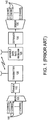
- FIG. 1 is a simplified block diagram of a prior art system for point-to-point communication.
- a mux 105 accepts several E1 communication channel inputs 110, and multiplexes the E1 communication channel inputs 110.
- the mux 105 outputs the multiplexed E1 communication channels into a framer 115, which packages blocks of multiplexed data into frames (not shown).
- the frames are transmitted by a transmitter 120.
- the frames are received by a variable data rate receiver 125, which transfers the frames to a deframer 130, which outputs a flow of multiplexed data to a demultiplexer 135.
- the demultiplexer 135 demultiplexes the multiplexed data into several E1 communication channels 140 corresponding to the E1 communication channel inputs 110, and outputs the E1 communication channels 140.
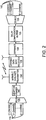
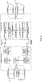
- FIG. 2 is a simplified block diagram of a variable data rate point-to-point communication system constructed and operative in accordance with an exemplary embodiment of the present invention.
- the mux 105 accepts several E1 communication channel inputs 110, and multiplexes the inputs 110.
- the mux 105 outputs the multiplexed E1 communication channels into an adaptive framer 145, which packages blocks of multiplexed data into frames, in a manner further described below with reference to FIG. 3 .
- the adaptive framer 145 outputs a flow of frames to a variable data rate transmitter 150, which transmits the frames.
- the mux 105 and the adaptive framer 145 are one unit, which accepts a plurality of inputs, and packages blocks of multiplexed data into frames.
- the multiplexed data may not be packaged in frames.
- Exemplary embodiments of the present invention maintain an errorless and hitless communication by maintaining a fixed delay, such that no loss of framing synchronization occurs during data rate changes, thereby providing uninterrupted and continuous service.
- the frames are received by the variable data rate receiver 125, which transfers the frames to the deframer 130, which outputs a flow of multiplexed data to a delay compensation buffer 155.
- the delay compensation buffer 155 outputs a flow of multiplexed data to the demultiplexer 135.
- the flow of multiplexed data being output by the delay compensation buffer 155 corresponds to the flow of frames being provided to the variable data rate transmitter 150, delayed by a substantially fixed period of time.
- the fixed period of time is substantially the period of time taken from entry of data into the system of FIG. 2 on the transmitter side, until exit from the system of FIG. 2 on the receiver side.
- the demultiplexer 135 demultiplexes the multiplexed data into several E1 communication channels 140 corresponding to the E1 communication channel inputs 110, and outputs the E1 communication channels 140.
- variable data rate transmitter 150 can be, by way of a non-limiting example, a transmitter using Adaptive Code Modulation (ACM), to transmit at varying data rates.
- ACM Adaptive Code Modulation
- the data rate is optionally selected as high as possible without introducing unacceptable error rates.
- Exemplary embodiments of the invention set a guaranteed capacity based on a worst case scenario, and add capacity of lower priority signals, optionally up to as high a data rate as possible without introducing unacceptable error rates.
- variable data rate transmitter 150 and the variable data rate receiver 125 communicate information about quality of transmission over a communication link between the variable data rate transmitter 150 and the variable data rate receiver 125.
- the information serves, at least partly, as a base for an agreement between the variable data rate transmitter 150 and the variable data rate receiver 125 as to which data rate should be used for data transmission over the communication link.
- variable data rate transmitter 150 and the variable data rate receiver 125 have agreed on a data rate for the data transmission over the communication link
- the system of FIG. 2 decides what portions of data to drop from or add to the data transmission.
- the portions of data to be dropped and transmitted can be entire communication channels, and the portions can be some packets of data within communication channels, such as, by way of a non-limiting example, some data packets from an Ethernet communication channel.
- the priorities associated with portions of data are set by various methods, such as described below with reference to FIG. 3 .
- the delay compensation buffer 155 maintains a substantially fixed delay between input of data to the mux 105 and output of data by the demux 135 by using a system and method for maintaining a substantially constant delay, over changing transmission data rates, such as described in a co-filed, co-pending and co-assigned patent application entitled "Maintaining a Constant Delay in Point-To-Point Transmission” (attorney docket no. 41861) by Gabi Yakov, the disclosure of which is hereby incorporated by reference.
- the delay compensation buffer 155 reads an indication of a data rate used to input data into the system of FIG. 2 from the data being presently output. The indication is used to set a data output rate.
- the system By outputting data from the system at a same rate as which the data was input into the system, the system maintains a constant delay. After a change of the input data rate, the output data rate changes when the first data input at a new rate arrives at the output of the system. Therefore, one may understand a section from an input to the system to an output of the system as an elastic buffer-like mechanism, which maintains the same output rate as input rate, for the same data, both during periods of fixed data rate transmission, and during changes of the data rate.
- the delay compensation buffer 155 maintains a substantially fixed delay between input of signals to the mux 105 and output of signals by the demux 135 by using an adaptive buffering scheme such as described by US Published Patent Application 2006/0077994 of Spindola et al and US Published Patent Application 2006/0109856 of Deshpande .
- Exemplary embodiments of the invention comprise a transmitter configured to drop signals according to priorities, and enabled to communicate with a receiver which is configured to receive transmitted signals and maintain an errorless and hitless reception of the transmitted signals.
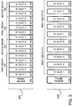
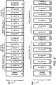
- FIG. 3 is a simplified illustration of frames transmitted by the communication system of FIG. 2 .
- a first frame 205 is depicted, produced by the adaptive framer 145 ( FIG. 1 ) when the variable data rate point-to-point communication system of FIG. 2 is operating in a high data rate mode.
- the first frame 205 comprises a frame header 206, and E1 channel slots 207.
- the communication system of FIG. 2 accepts 8 E1 communication channel inputs 110 ( FIG. 1 ).
- the digital data coming through the E1 communication channel inputs 110 is packaged in the E1 channel slots.
- data from a first E1 communication channel input 110 is packaged in an E1 slot 1 207
- data from a second E1 communication channel input 110 is packaged in an E1 slot 2 207, and so on.
- additional E1 slots 207 are populated with additional, following, data from the same corresponding E1 communication channel inputs 110, and so on.
- a second frame 220 is also depicted, produced by the adaptive framer 145 ( FIG. 1 ) when the variable data rate point-to-point communication system of FIG. 2 is operating in a data rate mode with lower data rate than depicted with reference to the first frame 205.
- the system of FIG. 2 therefore drops some data from transmission relative to the data transmitted by the first frame 205.
- the second frame 220 also comprises a frame header 206, and E1 channel slots 207.
- the variable data rate communication system of FIG. 2 is operating at a lower data rate, and has stopped populating E1 slots with data from the second group of communication channels 215.
- the adaptive framer 145 packages only data from the first group of communication channels 210, thus dropping the second group of channels 215.
- Data from more than two groups of communication channels can be packaged in a frame.
- the groups of communication channels are optionally arranged in a hierarchy of importance, or priority, and data from the communication channels is optionally dropped based on available data rate and in an order based on the hierarchy.
- the communication channel selected for which data is to be dropped can be arbitrary.
- the hierarchy of priority can be determined based, at least partly, on predetermined features of the E1 communication channel inputs 110 to the mux 105 ( FIG. 1 ) such as an order of input ports to which the E1 communication channels inputs 110 are connected; on operator inputs to a configuration mechanism which associates priorities to E1 communication channel inputs; and on a configuration mechanism which senses features of the data carried by the E1 communication channel inputs and associates priorities to the E1 communication channel inputs based at least partly on the features of the data.
- E1 slots need not be as depicted in FIG. 3 , that is, E1 slot 1, E1 slot 2, ... E 1 slot 8, and again, repeating the same order.
- the order can be any other order without affecting the operation of the communication system of FIG. 2 .
- the adaptive framer 145 When the variable data rate point-to-point communication system of FIG. 2 is operating in a data rate mode with higher data rate than depicted with reference to the second frame 220, the adaptive framer 145 correspondingly packages more data into a frame than is packaged in the second frame 220.
- E1 communication channel inputs applies as well to other PDH (Plesiochronous Digital Hierarchy) communication channels, such as, by way of a non-limiting example, T1 communication channels.
- PDH Physical Digital Hierarchy
- E1 communication channels applies as well to other types of communication channels, such as, by way of a non-limiting example, isochronous and synchronous communication channels.
- FIG. 4 is a simplified block diagram of an alternative embodiment of the communication system of FIG. 2 .
- the mux 105 accepts data from several E1 communication channel inputs 110, as well as data from several Ethernet communication channel inputs 405, and multiplexes the data from the E1 communication channel inputs 110 and the data from the Ethernet communication channel inputs 405.
- the mux 105 outputs the multiplexed data into an adaptive framer 145, which packages blocks of multiplexed data into frames, in a manner further described below with reference to FIG. 5 .
- the adaptive framer 145 outputs a flow of frames to a variable data rate transmitter 150, which transmits the frames.
- the frames are received by the variable data rate receiver 125, which transfers the frames to the deframer 130, which outputs a flow of multiplexed data to a delay compensation buffer 155.
- the delay compensation buffer 155 outputs a flow of multiplexed data to the demultiplexer 135.
- the flow of multiplexed data being output by the delay compensation buffer 155 corresponds to the flow of frames being provided to the variable data rate transmitter 150, delayed by a substantially fixed period of time.
- the demultiplexer 135 demultiplexes the multiplexed data into several E1 communication channels 140 corresponding to the E1 communication channel inputs 110, and several Ethernet communication channels 410 corresponding to the Ethernet inputs 405, and outputs the E1 communication channels 140 and the Ethernet communication channels 410.
- variable data rate transmitter 150 can be, by way of a non-limiting example, a transmitter using Adaptive Code Modulation (ACM), to transmit at varying data rates.
- ACM Adaptive Code Modulation
- the transmission data rates are optionally selected as high as possible without introducing unacceptable error rates.
- FIG. 5 is a simplified illustration of frames transmitted by the communication system of FIG. 4 .
- a first frame 505 is depicted, produced by the adaptive framer 145 ( FIG. 1 ) when the variable data rate point-to-point communication system of FIG. 4 is operating in a high data rate mode.
- the first frame 505 comprises a frame header 206, E1 channel slots 207, and slots for Ethernet packets 510.
- the communication system of FIG. 4 accepts 8 E1 communication channel inputs 110 ( FIG. 4 ) and several Ethernet communication channel inputs 405 ( FIG. 4 ).
- the data coming through the E1 communication channel inputs 110 are packaged in the E1 channel slots, and the data coming through the Ethernet communication channel inputs 405 are packaged in the slots for Ethernet packets 510.
- data from a first E1 communication channel input 110 is packaged in an E1 slot 1 207
- data from a second E1 communication channel input 110 is packaged in an E1 slot 2 207
- Data from the Ethernet communication channels is packaged in an Ethernet slot 510.
- additional E1 slots 207 are populated with additional, following, data from the same corresponding E1 communication channel inputs 110, and so on.
- additional Ethernet slots 510 can be interspersed within the first frame 505.
- first 5 E1 communication channel inputs 110 belong to a first group of channels 210
- the next 3 E1 communication channel inputs 110 belong to a second group of channels 215, and that the first group of channels 210 is considered more important than the second group of channels 215.
- some of the Ethernet data packets are considered more important than others, and possess an importance equal to the first group of channels 210, while other Ethernet data packets are of relatively lower importance.
- a second frame 515 is also depicted, produced by the adaptive framer 145 ( FIG. 4 ) when the variable data rate point-to-point communication system of FIG. 4 is operating in a data rate mode with lower data rate than depicted with reference to frame 505.
- the second frame 515 also comprises a frame header 206, E1 channel slots 207, and Ethernet slots 520.
- the variable data rate communication system of FIG. 4 is operating in lower data rate, and has stopped packaging E1 slots with data from the second group of communication channels 215, and has stopped packaging data from lower priority Ethernet data packets.
- the adaptive framer 145 packages only data from the first group of communication channels 210 and data from higher priority Ethernet data packets, thus dropping the second group of channels 215 and the lower priority Ethernet data packets.
- the same hierarchy of importance, or priority, applied to the data of the E1 communication channels can be applied to Ethernet data packets, using the same yardstick to measure priority in both types of communications.
- IEEE standard 802.1p defines 3 class-of-service bits which are embedded in packet headers, and which assist in determining which packets may receive which class of service from a communication link.
- An embodiment of the present invention determines priority of Ethernet packets based, at least partly, on the class-of-service bits.
- VoIP Voice-over-IP
- VoIP Voice-over-IP
- a VoIP communication channel is sensitive to changing delays and to dropped packets, and requires a high priority, thus becoming a communication channel which behaves similarly to a continuous communication channel, like a typical E1 channel.
- E1 channels are considered high priority, while other E1 channels are considered low priority, is inverse multiplexing from ATM to E1.
- E1 channels can contain both voice and data. By splitting voice and data to separate E1 channels, high and low priority E1 channels are obtained.
- a service level agreement determines a guaranteed bit rate for Ethernet packets, typically for high priority packet applications such as Voice-over-IP.
- E1 channels may be of lower priority than Ethernet packets having the guaranteed bit rate.
- Identification of the high priority Ethernet packets can be done in any suitable manner, such as, by way of a non-limiting example, using quality-of-service bits comprised in the Ethernet packets, using source address and/or target address comprised in the Ethernet packets, and so on.
- E1 channels when dropping E1 channels, remaining E1 channels do not experience a substantial increase in bit error rate, and do not experience a change in transmission delay over the point-to-point communication link.
- operators of exemplary embodiments of the system of the present invention are interested in defining a minimal number of E1 signals to be carried in a worst case scenario.
- Definition can be done in any suitable manner, such as, by way of a non-limiting example, by an order of input ports to which the E1 signal inputs are connected; by operator inputs to a configuration mechanism which associates priorities to E1 signal inputs; and by a configuration mechanism which senses features of the data carried by the E1 signals and associates priorities to the E1 signals based at least partly on the features of the data.
- the defining can be done directly at the communication system, or alternatively by remote communication with the communication system through a suitable system input.
- Exemplary embodiments of the invention are used in a cellular point-to-point link.
- An embodiment of the present invention uses more than one link for the point-to-point communication, and divides the data to be communicated among the more than one link according to a capacity of the links, as described in US Provisional Patent Application 60/929,943 of Yakov et al, filed 19 July 2007 .
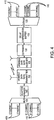
- FIG. 6 is a simplified block diagram of yet another alternative embodiment of the communication system of FIG. 2 .
- the system of FIG. 6 is an exemplary embodiment of the present invention which follows Yakov et al.
- the system of FIG. 6 depicts a point-to-point link ingress unit 605 and a point-to-point link egress unit 610, communicating via, by way of a non-limiting example, two wireless links: a first link 615, and a second link 620.
- the mux 105 accepts several E1 communication channel inputs 110, as well as several Ethernet communication channel inputs 405, and multiplexes the data from the E1 communication channel inputs 110 and the data from the Ethernet communication channel inputs 405.
- the mux 105 outputs the multiplexed data into a data splitting unit 625, which splits the multiplexed data to a first adaptive framer 630 and a second adaptive framer 635.
- the multiplexed data is split among the first adaptive framer 630 and the second adaptive framer 635 according to relative data rate capacities of the first link 615 and the second link 620, as described in the above-mentioned US Provisional Patent Application 60/929,943 of Yakov et al.
- the data is split such that portions of the data may be sent to either of the first adaptive framer 630 or the second adaptive framer 635.
- the portions within each of the adaptive framers 630 635 are kept in correct relative order. Indications of which data packaging plan was used by the adaptive framers 630 635 are packaged along with the data, so that the data can be reassembled in correct order by the egress unit 610.
- first adaptive framer 630 and the second adaptive framer 635 package the multiplexed data into frames as described above with reference to FIGs. 3 and 5 .
- the first adaptive framer 630 and the second adaptive framer 635 each send frames to a first variable data rate transmitter 640 and a second variable data rate transmitter 645 respectively.
- the first variable data rate transmitter 640 and the second variable data rate transmitter 645 each send the data frames over the first link 615 and the second link 620 respectively, to a first variable data rate receiver 650 and a second variable data rate receiver 655 respectively, which are comprised in the egress unit 610.
- the first variable data rate receiver 650 and the second variable data rate receiver 655 send the received frames to a first delay compensation buffer 656 and to a second delay compensation buffer 657 respectively.
- the first delay compensation buffer 656 and the second delay compensation buffer 657 operate substantially as described above with reference to the delay compensation buffer 155 of FIGs. 2 and 4 .
- the first delay compensation buffer 656 and the second delay compensation buffer 657 produce outputs of frames, which are provided to a first deframer 658 and a second deframer 659 respectively.
- the first deframer 658 and the second deframer 659 operate substantially as described above with reference to the deframer 130 of FIGs. 2 and 4 .
- the first deframer 658 and the second deframer 659 produce output of data which is sent to a data merging unit 660, which aligns the data and merges the data as described in the above-mentioned US Provisional Patent Application 60/929,943 of Yakov et al.
- the data merging unit 660 sends aligned and merged data to the demux 135, and the demux 135 produces output.
- the output can comprise several E1 communication channels 140 corresponding to E1 communication channel inputs 110 which were transmitted, and several Ethernet, communication channels 410 corresponding to transmitted portions of the Ethernet inputs 405, as described above with reference to FIGs. 2 and 4 .
- Embodiments of the present invention constructed according to the system of FIG. 6 provide an additional mode of flexibility to point-to-point communication systems.
- capacity of the first link 615 changes
- capacity of the second link 620 may or may not change in the same way.
- the data rate over the first link 615 may change, as well as the data rate over the second link 620.
- Some data may be shifted from one of the links, and added to another of the links, keeping higher priority data in transmission, all the while maintaining an errorless and hitless communication link.
Landscapes
- Engineering & Computer Science (AREA)
- Computer Networks & Wireless Communication (AREA)
- Signal Processing (AREA)
- Databases & Information Systems (AREA)
- Communication Control (AREA)
- Mobile Radio Communication Systems (AREA)
Claims (13)
- Drahtloser Transmitter mit variabler Datenübertragungsrate, der derart konfiguriert ist, um die Eingabe von Daten aus einer Vielzahl von Eingabekanälen zu empfangen und wenigstens einige der Daten über eine drahtlose, variable Datenübertragungsraten-Punkt-zu-Punkt-Nachrichtenverbindung zu übertragen, wobei der Transmitter derart konfiguriert ist, um Folgendes zu empfangen:die Eingabekanäle, umfassend wenigstens einen kontinuierlichen Kanal (110);die Eingabekanäle, umfassend wenigstens einen Kanal (405) basierend auf einem Datenpaket;wobei wenigstens einige der Kanäle mit Prioritäten assoziiert sind;wobei der drahtlose Transmitter dadurch gekennzeichnet ist, dass dieser derart konfiguriert ist, um die Übertragung wenigstens einiger der Kanäle zu ändern, wenigstens teilweise basierend auf den mit den Kanälen assoziierten Prioritäten sowie auf der für die Übertragung der Kanäle über die drahtlose, variable Datenübertragungsraten-Nachrichtenverbindung konfigurierten Datenübertragungsrate; undÜbertragung der Kanäle (215) mit niedriger Priorität ohne Veränderung der Übertragung von Kanälen (210) mit hoher Priorität.
- Drahtloser Transmitter mit variabler Datenübertragungsrate nach Anspruch 1 und ferner umfassend einen Multiplexer (105), der derart konfiguriert ist, um wenigstens einige der von der Vielzahl von Eingabekanälen empfangenen Kanäle zu multiplexen.
- Drahtloser Transmitter mit variabler Datenübertragungsrate nach Anspruch 1 und ferner umfassend einen adaptiven Rahmen (145), der derart konfiguriert ist, um wenigstens einige der Kanäle in den Datenrahmen zu bündeln.
- Drahtloser Transmitter mit variabler Datenübertragungsrate nach Anspruch 1 und wobei der Transmitter mit variabler Datenübertragungsrate derart konfiguriert ist, um Kanäle (110) von den aus dem wenigstens einen kontinuierlichen Kanal (110) übertragenen Kanälen fallenzulassen und diesen Kanäle (110) hinzuzufügen.
- Drahtloser Transmitter mit variabler Datenübertragungsrate nach Anspruch 1 und wobei der drahtlose Transmitter mit variabler Datenübertragungsrate derart konfiguriert ist, um Kanäle (405) von der Übertragung der aus dem wenigstens einen auf einem Paket basierenden Kanal (405) übertragenen Kanälen fallenzulassen und darselben Kanäle (405) hinzuzufügen.
- Drahtloser Empfänger mit variabler Datenübertragungsrate, der derart konfiguriert ist, um Daten über eine drahtlose, variable Datenübertragungsraten-Punkt-zu-Punkt-Nachrichtenverbindung, umfassend einen Verzögerungskompensationspuffer, zu empfangen, dadurch gekennzeichnet, dass:der Empfänger derart konfiguriert ist, um eine im Wesentlichen fixierte Verzögerung zwischen der Eingabe der Daten in einen drahtlosen Transmitter, der die Daten überträgt sowie der Ausgabe der Daten aus dem Verzögerungskompensationspuffer (155) durch Aufrechterhalten einer geeigneten Ausgaberate der Daten aus dem Verzögerungskompensationspuffer (155) aufrecht erhält.
- System, das derart konfiguriert ist, um wenigstens einige von einer Vielzahl von Kanälen über eine drahtlose, variable Datenübertragungsraten-Punkt-zu-Punkt-Nachrichtenverbindung zu übertragen, wobei das System Folgendes umfasst:einen drahtloser Transmitter mit variabler Datenübertragungsrate, der derart konfiguriert ist, um die Eingabe von Daten aus einer Vielzahl von Eingabekanälen zu empfangen, wobei die Eingabekanäle wenigstens einen kontinuierlichen Kanal (110) und wenigstens einen auf einem Paket basierenden Kanal (405) umfasst, und um wenigstens einige der Daten über eine drahtlose, variable Datenübertragungsraten-Punkt-zu-Punkt-Nachrichtenverbindung zu übertragen, wobei wenigstens einige Kanäle mit Prioritäten assoziiert sind; undeinen drahtlosen Empfänger mit variabler Datenübertragungsrate, um Empfangen der wenigstens einigen der Kanäle über die drahtlose, variable Datenübertragungsraten-Punkt-zu-Punkt-Nachrichtenverbindung,dadurch gekennzeichnet, dass:der drahtlose Transmitter derart konfiguriert ist, um die Übertragung von Kanälen (215) mit niedriger Priorität zu verändern, ohne die Übertragung von Kanälen (210) mit hoher Priorität zu verändern, basierend wenigstens teilweise auf den mit den Kanälen assoziierten Prioritäten und auf der für die Übertragung der Kanäle über die drahtlose, variable Datenübertragungsraten-Punkt-zu-Punkt-Nachrichtenverbindung konfigurierten Datenübertragungsrate; undder Empfänger einen Verzögerungskompensationspuffer (155) umfasst, der derart konfiguriert ist, um eine im Wesentlichen fixierte Verzögerung zwischen der Eingabe der wenigstens einigen der Kanäle in den drahtlosen Transmitter und der Ausgabe der wenigstens einigen der Kanäle aus dem Verzögerungskompensationspuffers aufrechtzuerhalten, indem eine geeignete Ausgaberate der wenigstens einigen der Kanäle aus dem Verzögerungskompensationspuffer aufrechterhalten wird.
- System nach Anspruch 7 und wobei die Veränderung der Übertragung der wenigstens einigen der Kanäle das Fallenlassen der wenigstens einigen der Kanäle aus der Übertragung umfasst.
- System nach Anspruch 7 und wobei die Veränderung der Übertragung der wenigstens einigen der Kanäle das Hinzufügen der wenigstens einigen der Kanäle aus der Übertragung umfasst.
- Verfahren zur Übertragung einer Vielzahl von Nachrichtenkanälen über eine drahtlose, variable Datenübertragungsraten-Punkt-zu-Punkt-Nachrichtenverbindung, wobei das Verfahren Folgendes umfasst:Empfangen der Eingabe von Daten aus einer Vielzahl von Eingabekanälen, wobei einige Kanäle mit Prioritäten assoziiert sind, wobei die Eingabekanäle wenigstens einen kontinuierlichen Kanal (110) und wenigstens einen auf einem Paket basierenden Kanal (405) umfassen;Verändern der Übertragung wenigstens einiger der Kanäle basierend wenigstens teilweise auf den mit den Kanälen assoziierten Prioritäten;Übertragen von wenigstens einigen der Kanäle über die drahtlose, variable Datenübertragungsraten-Punkt-zu-Punkt-Nachrichtenverbindung; undFeststellen, dass sich die variable Datenübertragungsrate verändert hat;gekennzeichnet durch:die Veränderung der Übertragung von Kanälen (215) mit niedriger Priorität ohne das Verändern der Übertragung von Kanälen (210) mit hoher Priorität unter Verwendung eines Verzögerungskompensationspuffers (155), um eine im Wesentlichen fixierte Verzögerung in den Anteilen der Daten aufrechtzuerhalten, die übertragen werden.
- Verfahren nach Anspruch 10 und wobei die Veränderung der Übertragung wenigstens einiger der Kanäle ein Fallenlassen der wenigstens einigen Kanäle aus der Übertragung umfasst.
- Verfahren nach Anspruch 10 und wobei die Veränderung der Übertragung der wenigstens einigen Kanäle ein Hinzufügen der wenigstens einigen Kanäle zur Übertragung umfasst.
- Verfahren nach Anspruch 10 und wobei die drahtlose, variable Datenübertragungsraten-Punkt-zu-Punkt-Nachrichtenverbindung eine Adaptive Codierung und Modulations-(ACM) drahtlose Punkt-zu-Punkt-Nachrichtenverbindung ist.
Applications Claiming Priority (2)
| Application Number | Priority Date | Filing Date | Title |
|---|---|---|---|
| US96028807P | 2007-09-24 | 2007-09-24 | |
| PCT/IL2008/001274 WO2009040800A1 (en) | 2007-09-24 | 2008-09-23 | Errorless and hitless variable data rate communications |
Publications (2)
| Publication Number | Publication Date |
|---|---|
| EP2195975A1 EP2195975A1 (de) | 2010-06-16 |
| EP2195975B1 true EP2195975B1 (de) | 2012-04-25 |
Family
ID=40328660
Family Applications (1)
| Application Number | Title | Priority Date | Filing Date |
|---|---|---|---|
| EP08808075A Not-in-force EP2195975B1 (de) | 2007-09-24 | 2008-09-23 | Fehlerlose und störungslose kommunikation mit variabler datenrate |
Country Status (5)
| Country | Link |
|---|---|
| US (1) | US8416693B2 (de) |
| EP (1) | EP2195975B1 (de) |
| AT (1) | ATE555576T1 (de) |
| CA (1) | CA2700404A1 (de) |
| WO (1) | WO2009040800A1 (de) |
Families Citing this family (5)
| Publication number | Priority date | Publication date | Assignee | Title |
|---|---|---|---|---|
| WO2009040800A1 (en) | 2007-09-24 | 2009-04-02 | Ceragon Networks Ltd. | Errorless and hitless variable data rate communications |
| WO2009040801A2 (en) | 2007-09-24 | 2009-04-02 | Ceragon Networks Ltd. | Protected variable data rate communication systems |
| US9277452B1 (en) | 2013-03-07 | 2016-03-01 | Dragonwave, Inc. | Adaptive modulation and priority-based flow control in wireless communications |
| US10306613B2 (en) | 2015-07-08 | 2019-05-28 | Ceragon Networks Ltd. | Dynamic channel allocation |
| US10382139B2 (en) | 2016-12-21 | 2019-08-13 | Ceragon Networks Ltd. | Polarization pre-coding for a single carrier communication system |
Family Cites Families (19)
| Publication number | Priority date | Publication date | Assignee | Title |
|---|---|---|---|---|
| FR2625399A1 (fr) * | 1987-12-23 | 1989-06-30 | Radiotechnique Ind & Comm | Dispositif de regulation de debit conjointe a au moins deux composantes de signaux video numeriques |
| FR2661298B1 (fr) * | 1990-04-23 | 1992-06-12 | Cit Alcatel | Procede et dispositif de retour a une liaison normale apres utilisation d'une liaison de secours dans un systeme de transmission de donnees. |
| US6138147A (en) | 1995-07-14 | 2000-10-24 | Oracle Corporation | Method and apparatus for implementing seamless playback of continuous media feeds |
| DE69739531D1 (de) * | 1996-05-29 | 2009-09-24 | Nippon Telegraph & Telephone | Einrichtung zur Übertragung von ATM-Zellen |
| CA2302269C (en) * | 1998-07-16 | 2003-11-04 | Samsung Electronics Co., Ltd. | Processing packet data in mobile communication system |
| EP1176725B1 (de) * | 2000-07-05 | 2013-03-13 | LG Electronics Inc. | Verfahren zur Übertragungskonfiguration in einem mobilen Kommunikationssystem |
| JP4642353B2 (ja) * | 2001-09-12 | 2011-03-02 | 富士通株式会社 | ネットワーク監視制御装置 |
| JP4075461B2 (ja) * | 2001-11-27 | 2008-04-16 | ソニー株式会社 | 通信システム、通信端末及び通信方法 |
| US7359979B2 (en) * | 2002-09-30 | 2008-04-15 | Avaya Technology Corp. | Packet prioritization and associated bandwidth and buffer management techniques for audio over IP |
| US7813273B2 (en) * | 2003-05-14 | 2010-10-12 | At&T Intellectual Property I, Lp | Soft packet dropping during digital audio packet-switched communications |
| JP2005094143A (ja) * | 2003-09-12 | 2005-04-07 | Uniden Corp | ダイバーシチ受信装置 |
| US7546508B2 (en) * | 2003-12-19 | 2009-06-09 | Nokia Corporation | Codec-assisted capacity enhancement of wireless VoIP |
| US8184657B2 (en) * | 2004-09-23 | 2012-05-22 | Sony Corporation | Reliable audio-video transmission system using multi-media diversity |
| US20070220184A1 (en) * | 2006-03-17 | 2007-09-20 | International Business Machines Corporation | Latency-locked loop (LLL) circuit, buffer including the circuit, and method of adjusting a data rate |
| US7643512B2 (en) * | 2006-06-29 | 2010-01-05 | Provigent Ltd. | Cascaded links with adaptive coding and modulation |
| US7839952B2 (en) * | 2006-12-05 | 2010-11-23 | Provigent Ltd | Data rate coordination in protected variable-rate links |
| US20100215054A1 (en) | 2007-09-24 | 2010-08-26 | Ceragon Networks Ltd. | Maintaining a constant delay in point-to-point transmission |
| WO2009040801A2 (en) | 2007-09-24 | 2009-04-02 | Ceragon Networks Ltd. | Protected variable data rate communication systems |
| WO2009040800A1 (en) | 2007-09-24 | 2009-04-02 | Ceragon Networks Ltd. | Errorless and hitless variable data rate communications |
-
2008
- 2008-09-23 WO PCT/IL2008/001274 patent/WO2009040800A1/en not_active Ceased
- 2008-09-23 CA CA2700404A patent/CA2700404A1/en not_active Abandoned
- 2008-09-23 US US12/678,515 patent/US8416693B2/en active Active
- 2008-09-23 EP EP08808075A patent/EP2195975B1/de not_active Not-in-force
- 2008-09-23 AT AT08808075T patent/ATE555576T1/de active
Also Published As
| Publication number | Publication date |
|---|---|
| US8416693B2 (en) | 2013-04-09 |
| EP2195975A1 (de) | 2010-06-16 |
| ATE555576T1 (de) | 2012-05-15 |
| WO2009040800A1 (en) | 2009-04-02 |
| CA2700404A1 (en) | 2009-04-02 |
| US20100214980A1 (en) | 2010-08-26 |
Similar Documents
| Publication | Publication Date | Title |
|---|---|---|
| US8514775B2 (en) | System and method for improving the use of radio spectrum in transmission of data | |
| US7817545B2 (en) | Jitter buffer for a circuit emulation service over an internal protocol network | |
| DK2958393T3 (en) | DISTRIBUTION OF BROADCAST / MULTICAST DATA IN TELECOMMUNICATION SYSTEMS | |
| US8208492B2 (en) | Method and apparatus for transmitting and receiving packets in a mobile communication system | |
| US11683739B2 (en) | Radio link aggregation | |
| CN101478476B (zh) | 一种分组微波数据的传输处理方法、装置及系统 | |
| US8804763B2 (en) | Transmission of data over parallel links | |
| US11349595B2 (en) | Service multiplexing method, service demultiplexing method, and related device | |
| EP2195975B1 (de) | Fehlerlose und störungslose kommunikation mit variabler datenrate | |
| EP2195974A1 (de) | Aufrechterhalten einer konstanten verzögerung bei der punkt-zu-punkt-übertragung | |
| KR20080022099A (ko) | 멀티캐리어 cdma 시스템 | |
| US8374147B2 (en) | System and method for protecting payload information in radio transmission | |
| WO2007024648A2 (en) | Methods and apparatus for differential encoding | |
| CA2610550C (en) | A method and system for providing via a data network information data for recovering a clock frequency | |
| US8009652B2 (en) | Information transmission in a communications system | |
| IL204618A (en) | Wireless communication at a variable rate | |
| US8077739B2 (en) | Methods, communication networks, and computer program products for communicating time division multiplexing traffic using a traffic encapsulation standard configured to support statistical multiplexing (STATMUX) traffic | |
| CN1227929C (zh) | 在无线电通信系统的不同单元之间传输数据的方法和为此建立的基站系统和无线电通信系统 | |
| KR20080073198A (ko) | 이동통신 시스템에서 가변적 크기의 패킷을 송수신하는방법 및 장치 |
Legal Events
| Date | Code | Title | Description |
|---|---|---|---|
| PUAI | Public reference made under article 153(3) epc to a published international application that has entered the european phase |
Free format text: ORIGINAL CODE: 0009012 |
|
| 17P | Request for examination filed |
Effective date: 20100416 |
|
| AK | Designated contracting states |
Kind code of ref document: A1 Designated state(s): AT BE BG CH CY CZ DE DK EE ES FI FR GB GR HR HU IE IS IT LI LT LU LV MC MT NL NO PL PT RO SE SI SK TR |
|
| AX | Request for extension of the european patent |
Extension state: AL BA MK RS |
|
| 17Q | First examination report despatched |
Effective date: 20100908 |
|
| DAX | Request for extension of the european patent (deleted) | ||
| GRAP | Despatch of communication of intention to grant a patent |
Free format text: ORIGINAL CODE: EPIDOSNIGR1 |
|
| GRAS | Grant fee paid |
Free format text: ORIGINAL CODE: EPIDOSNIGR3 |
|
| GRAA | (expected) grant |
Free format text: ORIGINAL CODE: 0009210 |
|
| AK | Designated contracting states |
Kind code of ref document: B1 Designated state(s): AT BE BG CH CY CZ DE DK EE ES FI FR GB GR HR HU IE IS IT LI LT LU LV MC MT NL NO PL PT RO SE SI SK TR |
|
| REG | Reference to a national code |
Ref country code: GB Ref legal event code: FG4D |
|
| REG | Reference to a national code |
Ref country code: CH Ref legal event code: EP |
|
| REG | Reference to a national code |
Ref country code: AT Ref legal event code: REF Ref document number: 555576 Country of ref document: AT Kind code of ref document: T Effective date: 20120515 |
|
| REG | Reference to a national code |
Ref country code: IE Ref legal event code: FG4D |
|
| REG | Reference to a national code |
Ref country code: DE Ref legal event code: R096 Ref document number: 602008015237 Country of ref document: DE Effective date: 20120621 |
|
| REG | Reference to a national code |
Ref country code: SE Ref legal event code: TRGR |
|
| REG | Reference to a national code |
Ref country code: NL Ref legal event code: VDEP Effective date: 20120425 |
|
| REG | Reference to a national code |
Ref country code: AT Ref legal event code: MK05 Ref document number: 555576 Country of ref document: AT Kind code of ref document: T Effective date: 20120425 |
|
| LTIE | Lt: invalidation of european patent or patent extension |
Effective date: 20120425 |
|
| PG25 | Lapsed in a contracting state [announced via postgrant information from national office to epo] |
Ref country code: PL Free format text: LAPSE BECAUSE OF FAILURE TO SUBMIT A TRANSLATION OF THE DESCRIPTION OR TO PAY THE FEE WITHIN THE PRESCRIBED TIME-LIMIT Effective date: 20120425 Ref country code: NO Free format text: LAPSE BECAUSE OF FAILURE TO SUBMIT A TRANSLATION OF THE DESCRIPTION OR TO PAY THE FEE WITHIN THE PRESCRIBED TIME-LIMIT Effective date: 20120725 Ref country code: IS Free format text: LAPSE BECAUSE OF FAILURE TO SUBMIT A TRANSLATION OF THE DESCRIPTION OR TO PAY THE FEE WITHIN THE PRESCRIBED TIME-LIMIT Effective date: 20120825 Ref country code: CY Free format text: LAPSE BECAUSE OF FAILURE TO SUBMIT A TRANSLATION OF THE DESCRIPTION OR TO PAY THE FEE WITHIN THE PRESCRIBED TIME-LIMIT Effective date: 20120425 Ref country code: LT Free format text: LAPSE BECAUSE OF FAILURE TO SUBMIT A TRANSLATION OF THE DESCRIPTION OR TO PAY THE FEE WITHIN THE PRESCRIBED TIME-LIMIT Effective date: 20120425 Ref country code: FI Free format text: LAPSE BECAUSE OF FAILURE TO SUBMIT A TRANSLATION OF THE DESCRIPTION OR TO PAY THE FEE WITHIN THE PRESCRIBED TIME-LIMIT Effective date: 20120425 |
|
| PG25 | Lapsed in a contracting state [announced via postgrant information from national office to epo] |
Ref country code: LV Free format text: LAPSE BECAUSE OF FAILURE TO SUBMIT A TRANSLATION OF THE DESCRIPTION OR TO PAY THE FEE WITHIN THE PRESCRIBED TIME-LIMIT Effective date: 20120425 Ref country code: HR Free format text: LAPSE BECAUSE OF FAILURE TO SUBMIT A TRANSLATION OF THE DESCRIPTION OR TO PAY THE FEE WITHIN THE PRESCRIBED TIME-LIMIT Effective date: 20120425 Ref country code: SI Free format text: LAPSE BECAUSE OF FAILURE TO SUBMIT A TRANSLATION OF THE DESCRIPTION OR TO PAY THE FEE WITHIN THE PRESCRIBED TIME-LIMIT Effective date: 20120425 Ref country code: PT Free format text: LAPSE BECAUSE OF FAILURE TO SUBMIT A TRANSLATION OF THE DESCRIPTION OR TO PAY THE FEE WITHIN THE PRESCRIBED TIME-LIMIT Effective date: 20120827 Ref country code: GR Free format text: LAPSE BECAUSE OF FAILURE TO SUBMIT A TRANSLATION OF THE DESCRIPTION OR TO PAY THE FEE WITHIN THE PRESCRIBED TIME-LIMIT Effective date: 20120726 |
|
| PG25 | Lapsed in a contracting state [announced via postgrant information from national office to epo] |
Ref country code: BE Free format text: LAPSE BECAUSE OF FAILURE TO SUBMIT A TRANSLATION OF THE DESCRIPTION OR TO PAY THE FEE WITHIN THE PRESCRIBED TIME-LIMIT Effective date: 20120425 |
|
| PG25 | Lapsed in a contracting state [announced via postgrant information from national office to epo] |
Ref country code: CZ Free format text: LAPSE BECAUSE OF FAILURE TO SUBMIT A TRANSLATION OF THE DESCRIPTION OR TO PAY THE FEE WITHIN THE PRESCRIBED TIME-LIMIT Effective date: 20120425 Ref country code: RO Free format text: LAPSE BECAUSE OF FAILURE TO SUBMIT A TRANSLATION OF THE DESCRIPTION OR TO PAY THE FEE WITHIN THE PRESCRIBED TIME-LIMIT Effective date: 20120425 Ref country code: EE Free format text: LAPSE BECAUSE OF FAILURE TO SUBMIT A TRANSLATION OF THE DESCRIPTION OR TO PAY THE FEE WITHIN THE PRESCRIBED TIME-LIMIT Effective date: 20120425 Ref country code: NL Free format text: LAPSE BECAUSE OF FAILURE TO SUBMIT A TRANSLATION OF THE DESCRIPTION OR TO PAY THE FEE WITHIN THE PRESCRIBED TIME-LIMIT Effective date: 20120425 Ref country code: AT Free format text: LAPSE BECAUSE OF FAILURE TO SUBMIT A TRANSLATION OF THE DESCRIPTION OR TO PAY THE FEE WITHIN THE PRESCRIBED TIME-LIMIT Effective date: 20120425 Ref country code: SK Free format text: LAPSE BECAUSE OF FAILURE TO SUBMIT A TRANSLATION OF THE DESCRIPTION OR TO PAY THE FEE WITHIN THE PRESCRIBED TIME-LIMIT Effective date: 20120425 Ref country code: DK Free format text: LAPSE BECAUSE OF FAILURE TO SUBMIT A TRANSLATION OF THE DESCRIPTION OR TO PAY THE FEE WITHIN THE PRESCRIBED TIME-LIMIT Effective date: 20120425 |
|
| PLBE | No opposition filed within time limit |
Free format text: ORIGINAL CODE: 0009261 |
|
| STAA | Information on the status of an ep patent application or granted ep patent |
Free format text: STATUS: NO OPPOSITION FILED WITHIN TIME LIMIT |
|
| 26N | No opposition filed |
Effective date: 20130128 |
|
| PG25 | Lapsed in a contracting state [announced via postgrant information from national office to epo] |
Ref country code: ES Free format text: LAPSE BECAUSE OF FAILURE TO SUBMIT A TRANSLATION OF THE DESCRIPTION OR TO PAY THE FEE WITHIN THE PRESCRIBED TIME-LIMIT Effective date: 20120805 Ref country code: MC Free format text: LAPSE BECAUSE OF NON-PAYMENT OF DUE FEES Effective date: 20120930 |
|
| REG | Reference to a national code |
Ref country code: CH Ref legal event code: PL |
|
| REG | Reference to a national code |
Ref country code: DE Ref legal event code: R097 Ref document number: 602008015237 Country of ref document: DE Effective date: 20130128 |
|
| REG | Reference to a national code |
Ref country code: IE Ref legal event code: MM4A |
|
| PG25 | Lapsed in a contracting state [announced via postgrant information from national office to epo] |
Ref country code: CH Free format text: LAPSE BECAUSE OF NON-PAYMENT OF DUE FEES Effective date: 20120930 Ref country code: BG Free format text: LAPSE BECAUSE OF FAILURE TO SUBMIT A TRANSLATION OF THE DESCRIPTION OR TO PAY THE FEE WITHIN THE PRESCRIBED TIME-LIMIT Effective date: 20120725 Ref country code: LI Free format text: LAPSE BECAUSE OF NON-PAYMENT OF DUE FEES Effective date: 20120930 Ref country code: IE Free format text: LAPSE BECAUSE OF NON-PAYMENT OF DUE FEES Effective date: 20120923 |
|
| PG25 | Lapsed in a contracting state [announced via postgrant information from national office to epo] |
Ref country code: MT Free format text: LAPSE BECAUSE OF FAILURE TO SUBMIT A TRANSLATION OF THE DESCRIPTION OR TO PAY THE FEE WITHIN THE PRESCRIBED TIME-LIMIT Effective date: 20120425 |
|
| PG25 | Lapsed in a contracting state [announced via postgrant information from national office to epo] |
Ref country code: TR Free format text: LAPSE BECAUSE OF FAILURE TO SUBMIT A TRANSLATION OF THE DESCRIPTION OR TO PAY THE FEE WITHIN THE PRESCRIBED TIME-LIMIT Effective date: 20120425 |
|
| PG25 | Lapsed in a contracting state [announced via postgrant information from national office to epo] |
Ref country code: LU Free format text: LAPSE BECAUSE OF NON-PAYMENT OF DUE FEES Effective date: 20120923 |
|
| PG25 | Lapsed in a contracting state [announced via postgrant information from national office to epo] |
Ref country code: HU Free format text: LAPSE BECAUSE OF FAILURE TO SUBMIT A TRANSLATION OF THE DESCRIPTION OR TO PAY THE FEE WITHIN THE PRESCRIBED TIME-LIMIT Effective date: 20080923 |
|
| REG | Reference to a national code |
Ref country code: FR Ref legal event code: PLFP Year of fee payment: 9 |
|
| REG | Reference to a national code |
Ref country code: FR Ref legal event code: PLFP Year of fee payment: 10 |
|
| REG | Reference to a national code |
Ref country code: FR Ref legal event code: PLFP Year of fee payment: 11 |
|
| REG | Reference to a national code |
Ref country code: FR Ref legal event code: PLFP Year of fee payment: 15 |
|
| PGFP | Annual fee paid to national office [announced via postgrant information from national office to epo] |
Ref country code: GB Payment date: 20230920 Year of fee payment: 16 |
|
| PGFP | Annual fee paid to national office [announced via postgrant information from national office to epo] |
Ref country code: SE Payment date: 20230920 Year of fee payment: 16 Ref country code: FR Payment date: 20230928 Year of fee payment: 16 Ref country code: DE Payment date: 20230920 Year of fee payment: 16 |
|
| PGFP | Annual fee paid to national office [announced via postgrant information from national office to epo] |
Ref country code: IT Payment date: 20230927 Year of fee payment: 16 |
|
| REG | Reference to a national code |
Ref country code: DE Ref legal event code: R119 Ref document number: 602008015237 Country of ref document: DE |
|
| REG | Reference to a national code |
Ref country code: SE Ref legal event code: EUG |
|
| GBPC | Gb: european patent ceased through non-payment of renewal fee |
Effective date: 20240923 |
|
| PG25 | Lapsed in a contracting state [announced via postgrant information from national office to epo] |
Ref country code: DE Free format text: LAPSE BECAUSE OF NON-PAYMENT OF DUE FEES Effective date: 20250401 |
|
| PG25 | Lapsed in a contracting state [announced via postgrant information from national office to epo] |
Ref country code: GB Free format text: LAPSE BECAUSE OF NON-PAYMENT OF DUE FEES Effective date: 20240923 |
|
| PG25 | Lapsed in a contracting state [announced via postgrant information from national office to epo] |
Ref country code: IT Free format text: LAPSE BECAUSE OF NON-PAYMENT OF DUE FEES Effective date: 20240923 |
|
| PG25 | Lapsed in a contracting state [announced via postgrant information from national office to epo] |
Ref country code: FR Free format text: LAPSE BECAUSE OF NON-PAYMENT OF DUE FEES Effective date: 20240930 |
|
| PG25 | Lapsed in a contracting state [announced via postgrant information from national office to epo] |
Ref country code: SE Free format text: LAPSE BECAUSE OF NON-PAYMENT OF DUE FEES Effective date: 20240924 |